Table of Contents
Advertisement
Quick Links
Advertisement
Table of Contents

Subscribe to Our Youtube Channel
Related Manuals for EOS LSG-Steam


Summary of Contents for EOS LSG-Steam
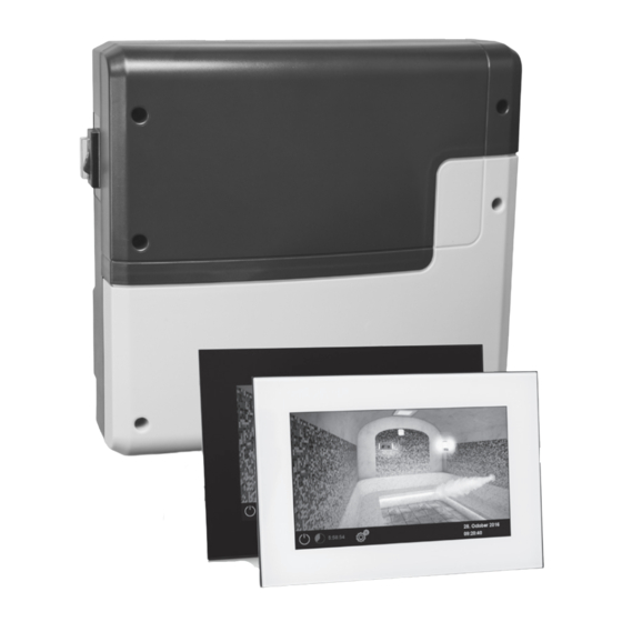
- Page 1 I N N O V A T I V E S A U N A T E C H N O L O G Y LSG-Steam for EmoTouch 3 control system for steam rooms display panel not included Installation and operation manual...
-
Page 2: Table Of Contents
English Content General advice for steam rooms ........................4 General safety notes ............................... 5 Descrption of the unit ............................8 Scope of delivery and optional accessories ....................8 Technical specifications ..........................9-10 Mechanical installation of the main unit ....................11-12 Display panel ................................13 Temperature sensor installation ....................... - Page 3 Recycling ..................................49 Service address ..............................49 General terms of service .............................50...
- Page 4 General information for steam rooms Dear customer, You have purchased a high-quality device that was developed and manufactured in com- pliance with the latest standards and quality guidelines. Please note that perfect interac- tion of the steam bath cabin, the steam gen- erator and control unit must be guaranteed to achieve the typical pleasant steam bath atmos- phere in your cabin.
- Page 5 General Safety Regulations This device can be used by children aged correctly, and there is a very low tempera- • 8 upwards and by persons with physical, ture fluctuation in the steam cabin. sensory, or mental disabilities, or persons The unit may only be used as intended as •...
- Page 6 Caution! Dear Customer, In compliance with the current regulations, only a qualified electrician may connect the electrical elements of the steam generator or the steam bath control unit. We would like to remind you that, in case of a warranty claim, you will need to pro- vide a copy of the authorised electronics company's invoice.
- Page 7 15.19 00109 Serial number EOS SAUNATECHNIK GmbH, 35759 Driedorf Intended use The LSG Steam control system in conjunction with the EmoTouch 3 display panel and a suitable steam generator is solely intended for heating of steam rooms cabins with steam.
-
Page 8: Descrption Of The Unit
Description of the unit LSG Steam consists of the main relay box, the temperature sensor and the corresponding connection cable. LSG Steam can be only used in conjunction with an EmoTouch 3 display panel, which is not included in the scope of delivery. Additional extension modules and consumers can be connected to the LSG Steam relay box, e.g. -
Page 9: Technical Specifications
Technical specifications Voltage (power supply): 230 V 1N AC 50 Hz Switching capacity: only switching signal Heating time limit: 6 h / 12 h / 18 h / unlimited Housing: plastic, shatter-resistant Operation: via external EmoTouch 3 display panel (not included) Temperature control range: 25 °... - Page 10 Place of installation requirement: Intended for indoor installation only. Main relay box may not be installed in corrosive environ- ment or in an environment which may cause water conden- sation. Dimensions main block: 270 x 300 x 100 mm Dimensions temperature sensor: 65 mm x Ø14 mm, stainless steel housing...
- Page 11 Installation of the main electronic unit The main electronic unit (relay box) may be installed only outside the cabin. The recommended places of installation are the outer cabin wall or the engineering room (plant room). If empty ducts for connection cables are already available, then they usually predetermine the installation posi- tion.
- Page 12 Hang the housing on the upper central screw in the upper central mounting hole. Insert the supplied rubber cable glands into the openings of the bottom of the housing (from below or from behind, as desired) and then guide the connection cables through these open- ings.
-
Page 13: Display Panel
Display panel The LSG Steam unit is designed to be used with the EmoTouch 3 control panel, which is not included in the scope of delivery. You can use for instance the already available EmoTouch 3 control panel of the sauna control system EmoTouch 3 or of the SteamRock II Premium steam generator. -
Page 14: Temperature Sensor Installation
Temperature sensor Except the sensor and cabin light lines also other connection cables and wires may need to be installed (e.g. surface heating). Install all lines to that they are properly protected, e.g. use a pro- tective cable channel NOTICE Electronics malfunctions The joined laying of data cable and power cables can cause interferences and lead to malfunc- tions, e.g. - Page 15 Installing the temperature sensor in the cabin 1. Drill a 20 mm opening 160–170 cm above the floor. 2. Route the temperature sensor housing through the hole. 3. Fix with silicone internally and externally (fill the gap around the sensor with silicone) 4.
- Page 16 Electrical connection This section describes the cable connections to the main board of the LSG Steam relay box. For setup of the control unit refer to the section „Commissioning“. Only suitable steam generators can be connected and operated by the LSG Steam control system. Verify in advance if the steam generator which you plan to connect is compatible.
- Page 17 Mains connection Steam generator connection DANGER Connect the steam generator as per installation Risk of electric shock manual of the manufacturer. A faulty electrical connection poses Lay the connection cable from the steam gen- the risk of an electric shock. erator and connect it to the terminals in the This risk also applies following completion of LSG Steam unit as per connection diagram (see...
-
Page 18: Lamp Connection
Lamp connection Heating time limitation The max. heating time may be limited with the jumper #5 on the main board of the relay box. The lamp must have the protection class The limitation may be set to 6, 12, 18 hours or of at least IP65 and should be resistant to the to unlimited. -
Page 19: Overview Of Connections
Overview of connections Temperaturfühler Sonde de temérature reserviert Sensorbus Leistungsteil Main unit (relay box) Relais box Saunabus Dampfgenerator Steam generator / générateur de vapeur L1 L2 L3 N W V U N S1 S1 N F L F N L L L N EmoTouch 3 Bedienteil Control panel... - Page 20 Connection example for LSG Steam with SteamRock II Basic Temperaturfühler SteamRock Basic Temperature sensor 9,0 kW Emotouch II+ Steam / LSG Steam reserviert N A2 L1 L2 L3 N N N N PE PE N S1 Wb PE Sensorbus Leistungsteil Main unit (relay box) Relais box 1 2 3 4 5 6 7 8 9 10 11 12 13 14 15 16 17...
-
Page 21: Setup (Commissioning)
Setup after initial start or after a reset The EmoTouch 3 control unit allows fast and intuitive configuration in several steps by commis- sioning during the first start or after a system reset. 1. Select language Tap on the required language symbol to Einstellungen select (the selection becomes highlighted) and tap again to confirm selection. - Page 22 2 steam rooms with up to 4 steam generators per cabin. 2 steam rooms with up to 2 steam generators each and up to 4 additional cabins. 6. Type of use Shall the cabin be used privately or commercially? Select and confirm: for private use, or for commercial use.
- Page 23 For this setting, the lighting must be disconnected. Changing the light type WARNING! Ensure that the control unit is disconnected from the power supply. Open the relay box housing (remove the housing cover) Disconnect the light source from the main circuit board. Reconnect the power supply and switch on the control unit.
- Page 24 Multi-cabin connection The EmoTouch 3 gives you the opportunity to operate several cabins with just one control panel. Free combination of up to 8 saunas and steam cabins can be connected. The connection is made via the 4 saunabus jacks on the rear side of the display panel. Please note that you will need a ferrite sleeve per connection to a jack.
- Page 25 Below you will find the connection overview with the example of connections for 8 cabins (6 saunas and 2 steam rooms). Reprogramming of the cabin addresses The relay box of the control unit or of the SteamRock II Premium steam generator is delivered (fac- tory set) with the default cabin address 1.
- Page 26 Example - connection of 8 cabins to the EmoTouch 3 display panel EmoTouch 3 Bedienteil Display panel Tableau de commande max. max. max. max. SAUNA SAUNA 9 kW 3 kW 3 kW 9 kW Saunaofen Verdampfer Verdampfer Saunaofen Sauna heater Vaporizer Vaporizer Sauna heater...
- Page 27 Display with several cabins As soon as you have connected more than one cabin with the corresponding cabin address (ID) to the display panel, the multi-cabin control symbol appears in the lower bar on the display. The number inside this symbol indicates the number of the currently selected cabin. 31.
-
Page 28: Operation
Operation Control panel - graphic user interface Coloured light (optional) Music control (optional) Cabin light Climate query Temperature setting press >3 sec to set Date, time 31. Oktober 2016 Cabin selection by 14:22:38 multiple cabins On / Off Fault press >3 sec to Status messages and warnings Settings switch on... - Page 29 Method of operating the graphic user interface Briefly touch to select or enable any of the functions available on the graphical user interface (cab- in icon). Keep touching a function (>3 sec) to access the associated settings screen. For safety reasons, you should always press certain symbols icons for more than 3 sec (e.g.
- Page 30 Make sure to remember the selected pin code! Please bear in mind that in the case this code is lost you will not be able to operate the control unit. In the case the pin code is no longer available and cannot be restored please contact your local EOS dealer or EOS service.
- Page 31 Graphic user interface GUI and climate conditions check Thanks to the modern GUI you can quickly access all functions and make necessary settings, as well as make a simple instant query for the current climate condition. The symbols on the start screen may be displayed in different colours, in order to indicate the current operation status - e.g.
-
Page 32: Operation
Operation and program settings Switching the heating ON/OFF Press the symbol for approx. 3 seconds. The heating will switch on and the display will show the active heating mode (see example on page 24). The light will be also switched on. To switch off the heating, touch the symbol again. - Page 33 Cabin light on/off Press the lamp on the display briefly to switch the light on or off. Light dimming You can dim the cabin light infinitely (0 - 100%) Settings to your preference. Light Touch the lamp symbol on the display for more 31.
- Page 34 the bottom line you will now see the programmed date and time, e.g. 15.01. and 18:30. Notice: The heating time duration will be as per „Auto-Stop“ setting (page 47). Week timer (recurring switching on the specified days of the week). Important notice: This function is only available by commercial use.
- Page 35 Error notification For mult-cabin operation only. The error symbol will be shown in the bottom line on the start screen to draw your attention that there is a fault / error in one of the connected cabins (not in the currently selected cabin). In such case touch briefly the multi-cabin control symbol to open the cabin overview and check the status of all connected cabins.
- Page 36 Extended settings Settings Einstellungen By private use touch briefly the symbol to display the Extended Settings menu. By commercial use press >3 sec on this symbol 5645 and give in the access code to open the Extended Settings menu. By multi-cabin control - this menu must be opened from the Cabin Overview interface.
- Page 37 Make sure to remember the selected pin code! Please bear in mind that in the case this code is lost you will not be able to operate the control unit. In the case the pin code is no longer available and cannot be restored please contact your local EOS dealer or EOS service.
- Page 38 Make sure to remember the selected pin code! Please bear in mind that in the case this code is lost you will not be able to operate the control unit. In the case the pin code is no longer available and cannot be restored please contact your local EOS dealer or EOS service.
-
Page 39: Potential Free Contact
Potential-free contact PFC (volt-free contact / dry contact) The PFC function allows you to switch some external equipment either manually or automatically. For instance the additional light circuit, music or others. manual switching off ) briefly symbol on the cabin wall. The PFC symbol is only shown when the PFC function has been enabled and set to manual operation. -
Page 40: Manual Setup Of The Lamp Type
Manual setup of the lamp type The factory default setting for the light output is the inductive load type of the lamp. The control unit supports resistive, inductive and capacitive types of loads connected to the light output and can be set up accordingly. Note: By the use of the conventional electric bulb leave the light output set to inductive loads. - Page 41 Service level settings Service level provides a range of additional functions for setup and fine-tuning of the control unit, in order to optimize operation. This setup menu is protected with a PIN-code to reduce the risk of unauthorized use. Touch the symbol for about 3 seconds until the PIN-code prompt window appears.
- Page 42 Symbol overview Service / maintenance intervals Setting the intervals for service / maintenance. Firmware Update Firmware update possibility for display panel, relay box or colour light module. Hysteresis Adjustment of the switching hysteresis. Usage Selection between private or commercial use. Reset Reset to the factory default settings, all individual settings will be deleted.
- Page 43 543210. The update menu will be launched directly. NOTICE Malfunction by power interrupt Make sure not to interrupt the power supply during the update process. The device may become unusable and has to be returned to EOS in such case.
- Page 44 Notice: Do not try to update the firmware without appropriate qualification! In the case of power supply loss, the device will attempt to resume the update process. If resuming the update fails or the display shows an error message, press the “Reset” button on the board next to the cell battery.
- Page 45 Potential-free contact (PFC) The terminals 3 and 4 on the main board of the relay box are a “NO / normally open” potential-free contact of a relay on this board. This output is not linked to any other connection and is therefore potential-free.
- Page 46 Switching “off” if there is water shortage in the vaporizer (only for Bi-O heaters) Switching for an additional vaporizer (synchronisation of switching with the output WB, only for Bi-O heaters) > 50° Switching “on“ if the current temperature reaches 50 °C. <...
- Page 47 ECO is an energy-saving function, which when active sets the air temperature to a lower level of 30°C. This allows to reduce the energy consumption while still keeping the cabin warm, so that it can return to normal temperature level in a shorter time. The heating must be switched on to use this function.
- Page 48 Troubleshooting Error messages and icons on the EmoTouch 3 display indicate operating statuses and fault conditions. In multi-cabin installations, the fault is displayed in the status bar by the icon. The cabin overview allows you to find and retrieve the cabin with the fault so you can access further details.
- Page 49 The “switch-off“ rocker switch The control unit is equipped with a “switch-off” rocker switch. You will find this switch on the left side of the main relay box. This switch allows to switch the control unit to standby mode (notice the heating will not start), to switch the control unit completely off (disconnect from power) or to switch the con- rocker switch...
- Page 50 2012/19/EU. Do not dispose it with the normal household waste. Service Address: EOS Saunatechnik GmbH Schneiderstriesch 1 35759 Driedorf, Germany Tel: +49 (0)2775 82-514 Fax: +49 (0)2775 82-431 servicecenter@eos-sauna.de...
- Page 51 The manufacturers General Terms and Conditions of Business, which can be found at www.eos-sauna.com/ V. Liability agb, shall apply in addition to the foregoing terms and conditions of service.
Need help?
Do you have a question about the LSG-Steam and is the answer not in the manual?
Questions and answers