BEAMEX MC6-T Manual
Multifunction temperature calibrator and communicator
Hide thumbs
Also See for MC6-T:
- Quick reference manual (13 pages) ,
- Quick reference manual (12 pages) ,
- Quick start manual
Table of Contents
Advertisement
Quick Links
Multifunction Temperature
Calibrator and Communicator
Applies to firmware version 4.00
Dear user,
We have made every effort to ensure the accuracy of the contents of this
manual. Should any errors be detected, we would greatly appreciate to
receive suggestions to improve the quality of the contents of this manual.
For more detailed technical data about Beamex MC6-T Multifunction
Temperature Calibrator and Communicator, please contact the
manufacturer.
MC6-T
© Beamex 2020
Beamex Oy Ab
Ristisuonraitti 10
FIN-68600 Pietarsaari
Finland
Tel:
E-mail:
Internet:
8862000 / MC6-TuEng / Version 4.00
+358-10-5505000
sales@beamex.com
service@beamex.com
https://www.beamex.com
Advertisement
Table of Contents

Subscribe to Our Youtube Channel
Related Manuals for BEAMEX MC6-T


Summary of Contents for BEAMEX MC6-T
- Page 1 Should any errors be detected, we would greatly appreciate to receive suggestions to improve the quality of the contents of this manual. For more detailed technical data about Beamex MC6-T Multifunction Temperature Calibrator and Communicator, please contact the manufacturer.
-
Page 3: Table Of Contents
General Warnings Concerning Pressure Measurement..16 Warnings Concerning High Pressure........17 General description............... 19 About MC6-T..................19 Hardware................. 19 General................19 MC6-T top view..............21 Connectors on the Left Side of MC6-T......22 MC6-T Handle..............22 Memory................23 Display................23 Batteries................. 23 Power Management..............24 User interface................28 PC Communication/Calibration software........ - Page 4 iv - Table of Contents Active Terminals and Connections........39 General.....................39 Measurements..................40 Temperature Measurement (Thermocouple)......40 Temperature Measurement (RTD)..........41 Resistance Measurement............42 Pressure Measurement............43 Connecting and Disconnecting External Pressure Modules..............43 Zeroing a Pressure Module........... 44 Current Measurement............. 44 Voltage Measurement............. 45 Frequency Measurement............
- Page 5 Instrument List Window Menu........87 Plant Structure Levels............88 Work Order View Mode..........88 Instrument Overview Window..........90 Calibrating an Instrument Using MC6-T......... 91 Changing the Pressure Module During Calibration..95 About Fieldbus and HART Device Specifics....96 Calibration Results................97 Deleting Calibration Results............98 Get mapped value feature...............
- Page 6 - Table of Contents Tools in MC6-T..............135 Saving Configurations..........135 Viewing/Managing Configurations........135 Beamex MC6 Fieldbus Configuration Viewer....... 136 Uploading Configurations..........137 Linking Configurations to CMX........137 Settings................. 139 Settings overview................139 Maintenance................141 Replacing the mains fuses............141 Overtemperature Protection Test Mode.........142 Cleaning instructions..............143...
-
Page 7: Prologue
Communicator. Beamex MC6-T is an advanced, high-accuracy field calibrator and communicator. It offers calibration capabilities for temperature, various electrical signals as well as pressure. MC6-T also contains a fieldbus communicator for HART, FOUNDATION Fieldbus and Profibus PA instruments. MC6-T consists of two main parts: Temperature Block and Process Calibrator. -
Page 8: About This Manual
Where am I? The header of each page in MC6-T User Manual informs you of where you are: The even page shows the part you are in and the odd page shows the main topic you are currently viewing. -
Page 9: Typographical Conventions
-at worst- damage the calibrator and/or even risk your life. Unpacking and Inspection At the factory each new MC6-T passes a careful inspection. It should be free of scrapes and scratches and in proper operation order upon receipt. The receiver should, however, inspect the unit for any damage that may have occurred during transportation. -
Page 10: Feedback
◦ a pair of Grabber clips and ◦ two pairs of Alligator clips, • USB cable, • "Stay up to date" card, which contains links to Beamex website, where different software tools (e.g. remote controller) can be downloaded from, Feedback We want to improve our products and services constantly. -
Page 11: Mc6-T Safety
IEC 61010-2-010:2014 IEC 61010-2-030:2010 Directive 2014/30/EU EN 61326-1:2013 Symbols Used The following symbols concerning safety are used on the MC6-T. Caution! See manual for further information Caution! Hot surface Operating Environment Warning: Only use the calibrator for purposes and in environments specified in the user manual. - Page 12 Note: Beamex provided temperature specifications are valid for ambient temperatures between 13..33 °C. Outside of this scope, temperature coefficients must be used. For more information about temperature coefficients see User Guide for Beamex CMX Calibration Software. Note: MC6-T150's heating/cooling modules undergo normal aging process during usage, after which minimum reachable calibration temperature may be higher.
-
Page 13: Safety Precautions And Warnings
1 m above the calibrator to allow correct ventilation. Warning: Use MC6-T only if you are certain of that it can be used safely. Safe use of MC6-T is no longer possible if one or more of the following cases are true: •... -
Page 14: Warnings Concerning Temperature
14 - MC6-T Safety Warnings Concerning Temperature Using the Temperature Block Warning: The MC6-T is a temperature calibrator which has been designed for calibrating instruments with typical industrial calibration procedures. It has not been designed for prolonged use at a temperature setpoint. Very low and very high temperatures may cause injuries if touched. -
Page 15: After Using The Temperature Block
Warnings Concerning Temperature - 15 Warning: MC6-T's handle must be in down position during calibration to prevent it from getting too hot. After using the Temperature Block Warning: If the Temperature Block has been heated up to temperatures above 50 °C, it must be cooled down below this temperature before switching off the device. -
Page 16: Warnings Concerning Electrical Measurement And Generation
Maximum output voltage from MC6-T's terminals is below 30 V. If you, however, connect together voltages from the IN and OUT sections or if you connect external voltages to MC6-T, the resulting voltage may be high enough to be hazardous. -
Page 17: Warnings Concerning High Pressure
Warnings Concerning Pressure - 17 Warning: Always depressurize the system before opening or connecting any pressure fittings or connectors. Use proper valves for venting the system. Ensure that all connections are made correctly and that the hose and the connectors are intact. External pressure modules have the allowed media printed on the module's sticker. - Page 18 18 - MC6-T Safety Warning: If you use nitrogen, minimize the leak to the atmosphere and take care of sufficient ventilation. Close the valve of the nitrogen cylinder, when the system is not in use. Increase in the percentage of nitrogen in the ambient air may cause unconsciousness and death without warning.
-
Page 19: General Description
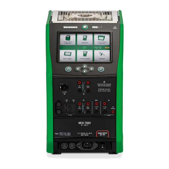
• Briefly about MC6-T's hardware and firmware • Available software and hardware options • Power management explanation About MC6-T Hardware General Figure 1: MC6-T, overview presents a general view of the MC6-T, its parts and its buttons' functionality. Figure 1: MC6-T, overview... - Page 20 20 - General description Legend: Temperature Block. See also Figure 3: MC6-T, top view. Display and Touch Panel. Home button. Press this button to return to Home View. Hot Temperature warning symbol that lights up when the Temperature Block is hot.
-
Page 21: Mc6-T Top View
About MC6-T - 21 Figure 2: Outside view of the female connector in MC6-T R2 connector's pin order: Excitation current + Sense + Not in use Sense - Excitation current - Not in use Not in use MC6-T top view... -
Page 22: Connectors On The Left Side Of Mc6-T
This connector is used for Beamex internal purposes only. The optional Internal Barometric Pressure Module. It has a venting hole on the side of MC6-T. To ensure valid barometric pressure measurements, do not plug the venting hole. PX. A possibility to connect Beamex External Pressure Modules to MC6-T. -
Page 23: Memory
Available memory can be used for anything that requires it (e.g. instrument data, calibration results, etc.). Display MC6-T has a backlit 640 × 480 pixel 5.7" TFT Display and Touch Panel. Use the touch screen with your fingers, gloves on or off. Optionally, use a stylus meant for touch screen use. -
Page 24: Power Management
Remember to check the capacity of the batteries from time to time eventhough MC6-T is not in use. Power it on if a recharge is needed. Tap the battery icon to open a window displaying detailed battery/charging information. - Page 25 Set temperature setpoint close to ambient to minimize cooling time. If you fail to switch the Mains switch back on, the MC6-T will go to the Standby mode after it is safe.
- Page 26 26 - General description Note: When Mains switch is on, Calibrator Power Off and Standby are not active due to safety reasons. Power off MC6-T from the Mains switch. Figure 7: Power Menu dialog Figure 8: Power Management window Pressing Tools button in Power Menu will take you to Power Management...
- Page 27 About MC6-T - 27 Note: Auto-off is not active when calibrator is in use. The startup procedure ends in Home View. From MC6-T's Home View you may advance to any of the available main operational modes. This manual contains detailed information about main operational modes as follows: •...
-
Page 28: User Interface
28 - General description User interface You can interact with MC6-T by tapping on available buttons/controls displayed on the touch screen. Optionally: use the hardware arrow keys to move between the available buttons/controls. The first time you push a hardware arrow key the Hardware Focus Indicator is displayed (a blue border around the active button/control). - Page 29 Computers. Figure 15: Check Boxes, both a checked and an unchecked one MC6-T also has some "flat" buttons. They are used in, e.g. lists. The color of the flat buttons may vary depending on the context. The following editable fields are available: •...
- Page 30 30 - General description Figure 16: Example of a list with flat buttons The letters/numbers on all editable fields are blue to indicate that they are editable. Black texts are descriptive user interface texts that are not editable. An example of a Text Field and the Text Edit Window are shown Figure 17: Text Field Figure 18: Text Edit window.
- Page 31 Date Fields are actually special cases of Numeric Fields. Entering the date is just like entering any numeric value. Setting MC6-T's time is a special case of the Spinning functionality. The "Left" and "Right" arrow buttons move the highlight to another digit. The "Up"...
-
Page 32: Pc Communication/Calibration Software
Look for Download Center and Software tools for MC6 family. • Beamex MC6 Data Log Viewer, for transferring Data Log results to a PC and viewing them on the PC. • Beamex MC6 Device Description Installer, for installing new Device Descriptions of smart transmitters from the PC to MC6-T. -
Page 33: Options
Software Options The following software options are available: • Mobile Security Plus, a solution which ensures the integrity of calibration data throughout the Beamex ICS solution. This option is also required in CMX Calibration Software, • Multi channel Data Logger, •... -
Page 34: Hardware Modules/Options And Accessories
• Pressure Hose Sets to be used together with external Pressure Modules. Accessory Holder Kit MC6-T offers an optional Accessory Holder Kit, available for both models, which allows to: • comfortably transport the accessories in the field, • store additional accessories, •... - Page 35 Options - 35 Figure 20: Accessory Holder Kit, fully equipped (MC6-T150 on the left, MC6-T660 on the right) Legend: Cut-outs designed to store additional inserts. Insert removal tool. Mains cord holder. Heat Shield. Heat Shield Holder. Heat Shield Tongue. Cut-outs for storing insert insulations (MC6-T150 model only). Assembly The Accessory Holder Kit delivered separately includes the tool needed for the assembly (Torx T20).
- Page 36 36 - General description Figure 21: MC6-T660 Transportation position To install the Heat Shield (MC6-T660 model only), first connect the two parts of the Heat Shield Holder by twisting them together, then twist the whole Heat Shield Holder in place (there is a right side threaded hole in the bottom part of the Accessory Holder Kit).
-
Page 37: Related Products
Options - 37 Related Products There are an increasing number of devices that can be used together with MC6-T. The following list includes devices that are already available (valid when this manual was printed): • Temperature sensors ◦ Reference sensor RPRT-660 (straight and bent model), ◦... - Page 38 38 - General description...
-
Page 39: Active Terminals And Connections
This section of MC6-T User Manual presents all measurements and generations/simulations that MC6-T is capable of performing. No matter which of the available main functions you use in MC6-T, the connections presented here apply. Settings in Temperature Calibrator or Calibrator are saved, so that the next time you measure, generate or simulate something, the previous settings are available as defaults. -
Page 40: Measurements
TC plugs. TC2 is for TC plugs with flat contacts. Check the Sensor Type. Your measurement results are unreliable unless you select the same sensor type as is connected to MC6-T. Select also a suitable Reference Junction compensation method. Wrong settings yield useless measurement results. -
Page 41: Temperature Measurement (Rtd)
Temperature Measurement (RTD) Check the Sensor Type. Make sure you select the same sensor type as is connected to the MC6-T. Otherwise your measurement results are useless. For R1 and R3 terminals: The two leftmost terminals are used in 2-wire systems. MC6-T automatically checks the connection and displays the found wiring system (2-wire, 3-wire or 4-wire). -
Page 42: Resistance Measurement
Resistance Measurement For R1 and R3 terminals: The two leftmost terminals are used in 2-wire systems. MC6-T automatically checks the connection and displays the wiring system found (2-wire, 3-wire or 4-wire). Note: For the 3-wire system measurements use the connector marked with "3W". -
Page 43: Pressure Measurement
Pressure Measurement MC6-T supports the use of external pressure modules, EXT, when they are connected to MC6-T's PX connector. MC6-T also includes an optional internal Barometric Module for measuring barometric pressure and together with a gauge EXT module, MC6-T indicates the absolute pressure of any pressure the EXT module is capable of measuring. -
Page 44: Zeroing A Pressure Module
Current Measurement When measuring electric current, an important thing is selecting whether MC6-T provides the 24 V loop supply voltage or not. If not, an external device should provide the loop supply voltage. Connection depends on the loop supply setting. -
Page 45: Voltage Measurement
Measurements - 45 Voltage Measurement MC6-T's voltage measurement terminals are listed below as they are shown in Figure 28: Voltage measurement terminals: • TC1, measurement range: -1.01 to +1.01 VDC. • TC2, measurement range: -1.01 to +1.01 VDC. • IN, measurement range: -1.01 to +60.6 VDC. -
Page 46: Pulse Counting
46 - Active Terminals and Connections Figure 29: Frequency measurement terminals. Range 0.0027 … 51000 See also Frequency Generation, Pulse Counting Switch Sensing. Note: There is a trigger level choice for (dry) contacts with no external potential. 24 V supply may also be used. Connect as light blue line shows in picture above. -
Page 47: Switch Sensing
There are several ways of changing the generated/simulated value. The following subchapters present the available utilities. Using the Soft Numeric Keypad This tool is useful when a generated/simulated value (or any numeric field in MC6-T) is either empty (displaying dashes) or when a new and different... -
Page 48: Spinning
When applicable, the minimum and maximum limit of the entered value is shown above the entered number. If you enter a value above/below the limits, and try to accept it, MC6-T stays in the soft numeric keypad window and replaces the entered value with appropriate limit value and highlights the replaced value. -
Page 49: Temperature Generation
Generations/Simulations - 49 Figure 34: Active spinner Non-empty numeric fields in Calibrator's generation/simulation windows have a button with both "Up" and "Down" arrows to the left of the actual numeric value. That is the Spinner button. Tap the Spinner button to activate spinning. -
Page 50: Inserts To Be Used In The Temperature Block
Be patient. Inserts to be used in the Temperature Block Warning: For reliable and safe performance of the calibrator, only use original Beamex MC6-T inserts. -
Page 51: Thermocouple Simulation
Thermocouple simulation is available from TC1 terminals only. Check the Sensor Type. Your simulations are unreliable unless you select the same sensor type as is connected to MC6-T. Also select a suitable Reference Junction compensation method. Wrong Reference Junction setting yields useless results. See chapter Thermocouple Connections. -
Page 52: Rtd Sensor Simulation
52 - Active Terminals and Connections Warning: When using a thermocouple or an RTD sensor connected to MC6-T to measure the external reference junction temperature: Keep in mind that there is no galvanic isolation between the sensors. Note: Thermocouple measurements are error prone. There may be faulty connections, wrong (extension) cables and settings in MC6-T. -
Page 53: Current Generation (Source Or Sink)
Generations/Simulations - 53 Current Generation (Source or Sink) MC6-T's current generation can be done using one of two available methods: • MC6-T provides a 24 V loop supply voltage (source mode). Setting: Supply: On. • An external device provides the loop supply voltage (sink mode) Setting: Supply: Off. -
Page 54: Voltage Generation
RTD1 terminals in MC6-T. See Figure 41: Resistance simulation terminals. Range 0 … 4000 Ohm. MC6-T monitors the resistance measurement current. If the current is too high, MC6-T cannot simulate the right resistance value and displays an error message. -
Page 55: Frequency Generation
RTD Sensor Simulation. Note: When simulating resistance or an RTD sensor, using R1 port, MC6-T does not support measuring the simulated signal using R2 port. To ensure good contact between the device under test and the test leads, we recommend using the alligator clips provided with MC6-T. -
Page 56: Pulse Generation
56 - Active Terminals and Connections Figure 42: Frequency generation terminals. Range 0.0005 … 50000 Hz See also Frequency Measurement Pulse Generation. Pulse Generation Before generating pulses, the following settings should be checked: • Frequency. To set the frequency, tap on the button with the "Hz" value. •... -
Page 57: Thermocouple Connections
With thermocouples, connections and reference junction settings are crucial for getting accurate results. Reference Junction Modes available: Internal is the simplest. Use suitable thermocouple, extension or compensation wires to connect to MC6-T. MC6-T takes care of the Reference Junction compensation. See Figure 44: Internal Reference Junction. - Page 58 58 - Active Terminals and Connections Figure 46: Fixed/Manual Reference Junction temperature Warning: Before measuring, ensure that device's internal temperature has stabilized. Temperature differences between MC6-T and the environment affect the accuracy of TC measurements. In extreme conditions, wait up to 90 minutes.
-
Page 59: Tools
- 59 Tools MC6-T has Tools buttons in the lower left corner of certain subwindows. The lists in the following subchapters present available tools. Certain tools are available for measurements only and others for generations/ simulations only. Figure 47: Tools button Note: The available tools also depend on the selected Quantity and Function, e.g. -
Page 60: Tools For Measurements
60 - Tools Tools for Measurements Figure 48: Tools for measurements (as seen in Temprature Calibrator) Tool Description Available in Scaling Any signal may be scaled • Temperature provided the conversion Calibrator is known. When scaling is • Calibrator active, it is indicated with a •... - Page 61 Tools for Measurements - 61 Tool Description Available in Leak / Stability A leak/stability test may • Temperature Test be assigned to main Calibrator measurements. It tests the • Calibrator leak or stability of, e.g. a • Documenting pressure measurement Calibrator system.
-
Page 62: Additional Stability Check
62 - Tools Tool Description Available in Additional Additional Stability Check is • Temperature Stability Check available for temperature Calibrator measurements. It is an • Calibrator addition to the default • Documenting stability check ensuring that Calibrator* slow temperature transients •... - Page 63 Tools for Measurements - 63 either 1 or 2-minute time window for the rolling 2 x STDDEV (2σ) stability calculation. Temperature generation in the Temperature Block always use 1-minute Additional Stability Check. When Additional Stability Check has been enabled for a temperature measurement, the calculated 2σ...
-
Page 64: Tools For Generations/Simulations
64 - Tools Tools for Generations/Simulations Figure 49: Tools for generations and simulations (as seen in Calibrator) Tool Description Available in Scaling Any signal may be scaled • Temperature provided the conversion Calibrator is known. When scaling is • Calibrator active, it is indicated with a •... - Page 65 Tools for Generations/Simulations - 65 Tool Description Available in which starts after stability criteria has been met.* * The Step option includes the possibility to use steps when increasing/ decreasing the temperature. It is usable, if you manually document the calibration data.
- Page 66 66 - Tools...
-
Page 67: Temperature Calibrator
Any supported RTD and thermocouple sensor may be calibrated as well as any temperature instrument if the output signal can be read by MC6-T. Up to three instruments may be calibrated simultaneously. Figure 50: Home View with Temperature Calibrator selected Note: Keyed output is not supported in Temperature Calibrator. - Page 68 (2σ). • The red "thermometer" and a percentage value indicates that currently MC6-T is heating with 88 % power. If the "thermometer" is blue, MC6-T is cooling the Temperature Block. • The tools button on the bottom left is described in chapter Tools.
- Page 69 Figure 53: Title bar's active area (shown in yellow) for toggling between main view and graph view Note: If you want to document your calibration results, use MC6-T's Documenting Calibrator feature or manually document the calibration data displayed in Temperature Calibrator.
-
Page 70: The Menu
• Toggle View for changing between the main view and graph view (same as tapping on the title bar's active area for togging view). • Reset Graph for clearing the trend lines. MC6-T recalculates the minimums and maximums based on current measurements/ calculations. -
Page 71: Calibrator
For example one subwindow for the instrument's input and another for the instrument's output. Figure 55: Home View with Calibrator selected Start the Calibrator by tapping on the Calibrator icon in MC6-T's Home View (see Figure 55: Home View with Calibrator selected). - Page 72 Note however, that proper calibration of temperature switches should be done in Documenting Calibrator. Note: If you want to automatically document your calibration results, use MC6-T's Documenting Calibrator feature. For information on External Devices (Pressure and Temperature Controllers) used together with Calibrator, see chapter Additional Information.
-
Page 73: Documenting Calibrator
• How to read instrument data from devices using digital communication. General MC6-T's Documenting Calibrator is a more advanced tool than the "plain" Calibrator that is also available in MC6-T. Configurations of the instruments to be calibrated may be received from calibration software communicating with MC6-T. -
Page 74: Calibration Software
74 - Documenting Calibrator Calibration results are saved and they can be viewed in MC6-T and also sent to calibration software for further analysis. Open Documenting Calibrator by tapping on the Documenting Calibrator icon in MC6-T's Home View (see Figure 57: Home View with Documenting Calibrator selected). -
Page 75: Generating/Simulating The Input Value
Calibrating Instruments - 75 Figure 58: Typical calibration procedure Note: Although MC6-T assists you in doing the calibration, you need to know how instruments are calibrated; be, e.g. a calibration technician. MC6-T is a tool for calibration professionals. Generating/Simulating the Input Value... -
Page 76: Instruments
76 - Documenting Calibrator MC6-T allows you to hierarchically organize your instruments into a Plant Structure. The Instrument List window may contain both instruments (gray items) and Plant Structure Levels (yellow items). The following subchapters present features available in Instrument List window and its menu. - Page 77 Calibrating Instruments - 77 Figure 61: Instrument's latest calibration "Failed" To select an instrument for calibration, tap on it. Then the Instrument Overview Window, opens. Creating Instruments To create a new instrument, tap the "Create New Instrument" button. See Figure 62: "Create New Instrument" button.
- Page 78 78 - Documenting Calibrator Figure 64: Temperature Instrument Wizard, Input Method Available methods for calibrating temperature instruments are: • Generated/Controlled (available when Temperature Block is enabled) - calibrator generates the temperature with internal Temperature Block or controlls the temperature generation by an external device. This method can be used with internal or external reference sensor (see figure Figure 65: Documenting Calibrator, reference sensor selection...
- Page 79 Calibrating Instruments - 79 If RTD Temperature or TC Temperature is selected, the option Automatic Control will appear. Calibrator will set the calibration points. Continue the instrument setup by modifying several pages of instrument configuration data. Note that by default only basic pages are shown. View all pages by selecting Show, All Pages from the menu available when creating/editing an instrument.
- Page 80 80 - Documenting Calibrator Figure 66: Creating new instrument - configuration, page 1 Second page of the creating new instrument configuration data is Output related. For most of the Quantities same parameters are available, with couple of additional settings (see table Table 2: Additional Output parameters).
- Page 81 Calibrating Instruments - 81 Figure 67: Creating new instrument - configuration, page 3 Fourth page of the creating new instrument configuration data (Procedure) describes parameters: • Calibration Points (Predefined) - define own calibration steps (number of steps, step size and percentage) or select one of the predefined sets; •...
- Page 82 82 - Documenting Calibrator Figure 68: Creating new instrument - configuration, page 4 Fifth page of the creating new instrument configuration data (Error Limit) allows to select Error Calculation Method (Error Unit and Error Reference). It also serves as a place to set up the measurement error limits (instrument range can be divided up to 10 subranges, each having their own error limit).
- Page 83 Calibrating Instruments - 83 Note: If you plan to transfer the result to CMX or to LOGiCAL, it is highly recommended that at minimum, the Position ID and the Device ID fields are filled, as they are required fields in the calibration management software.
- Page 84 84 - Documenting Calibrator Figure 71: Creating new instrument - additional configuration page 1 Second page of the creating new instrument configuration data (Other Error Limits) helps to define additional error limits and possible messages about instrument adjusting needs. Figure 72: Creating new instrument - additional configuration page 2 Add calibration and adjustment related notes with third page of the configuration (Notes).
- Page 85 Calibrating Instruments - 85 Figure 73: Creating new instrument - additional configuration page 3 Fourth additional configuration page (General) shows different fields related to the amount of repeats, calibration interval and interval units. Figure 74: Creating new instrument - additional configuration page 4 The last configuration page (Device) allows to input general data such as Location, Sensor Serial Number, Manufacturer and Model.
- Page 86 86 - Documenting Calibrator Figure 75: Creating new instrument - additional configuration page 5 To delete an instrument, select it and use the delete command available in the menu of opened Instrument Overview Window. Temperature Instrument Specifics If you are creating an instrument where the input is temperature related, take note of the following specifics: •...
-
Page 87: Instrument List Window Menu
Calibrating Instruments - 87 Instrument List Window Menu The Instrument List window's menu contains a lot of useful tools: • Create New for creating a new Instrument etc. (See Figure 76: Instrument List Window's menu) • Sort for sorting the list contents alphabetically etc. Sorting icons shown in status bar (ascending / descending): Identification Due Date... -
Page 88: Plant Structure Levels
Work Order View Mode Work Order View Mode is an optional way of viewing the instruments. This option is of use, when instruments have been sent from Beamex CMX Calibration Software together with Work Orders in their Calibration Procedure. See... - Page 89 Calibrating Instruments - 89 Figure 79: Activating Work Order View Mode If Work Order View is active, a list of Work Orders are shown. Work Orders have green background, the upper right corner is folded and the left side has a blue line. The data in a Work Order are as follows: •...
-
Page 90: Instrument Overview Window
Instrument's general data and on a separate page among instrument data. All basic data of Work Orders (Work Order Number and dates) are read only data in MC6-T. When Work Order View Mode is active, Plant Structure is not shown and instruments may not be copied or moved within the structure. -
Page 91: Calibrating An Instrument Using Mc6-T
• start calibrating the selected instrument and open the calibration window ( Note that the menu contains some useful instrument related tools. Calibrating an Instrument Using MC6-T When you start calibrating an instrument, the Calibration window opens. Figure 83: Button for zeroing a pressure module (lower right corner). - Page 92 When Automatic Acceptance is in use (checked), MC6-T accepts calibration point automatically as follows: MC6-T uses the Max. Point Deviation value to see if the input signal is close enough to the next calibration point. When close enough, MC6-T checks the signal stability to decide whether the readings can be saved or not.
- Page 93 Calibrating Instruments - 93 Figure 84: Calibration with Automatic Acceptance in use Use the Force Accept button to manually accept points when, e.g. the calibration does not advance because of an unstable input and/or output signal. Note: Opening the menu during calibration pauses the calibration for as long as the menu is open.
- Page 94 94 - Documenting Calibrator As the calibration advances, the graph is drawn from point to point. A grey column indicates where next target point is. The width of the grey column is based on Max. Point Deviation setting. Numeric values for the next target point can be seen in the lower right corner.
-
Page 95: Changing The Pressure Module During Calibration
• If you want to change the External Pressure module in use to another External Pressure Module connectable to the same port as the one currently in use, tap on the button seen in Figure 88: Switching/ changing an external pressure module.. Continue with the change as explained on MC6-T's display. -
Page 96: About Fieldbus And Hart Device Specifics
Calibrator. Adding fieldbus and HART Instrument to MC6-T's database When adding a fieldbus instrument or a HART instrument's digital output to MC6-T's database, select HART, FOUNDATION Fieldbus H1 or Profibus PA as the output quantity. See Figure 89: Documenting Calibrator's quantity selection window. -
Page 97: Calibration Results
Calibration Results - 97 method. For fieldbus instruments, an additional menu option for trimming the instrument is also available. Figure 90: Menu in Documenting Calibrator when calibrating a HART instrument Calibration Results Once an instrument has been calibrated, you may view saved calibration results as follows: •... -
Page 98: Deleting Calibration Results
Get mapped value feature With the “Get mapped value” feature you can automatically read certain data from connected smart transmitter to the MC6-T instrument data. This automates process of creation of a new instrument to the MC6-T. This is very useful especially with the long data fields, as they don't need... -
Page 99: Getting And Editing Mapped Data
MC6-T's Instrument Data. No error prone manual entry of Instrument Data. MC6-T has pre-entered default mappings (which Digital Communication Instrument field goes to which field in MC6-T) but you may customize the mapping for each instrument model you use. Note: Utilizing this feature requires that your MC6-T has the option to communicate with the smart instrument type (Fieldbus option) you want to add to MC6-T's instrument data. -
Page 100: Getting Default Mappings
In the Figure 93: Sample of default mappings for HART protocol can see a sample of the mappings. The left side lists the fields in MC6-T (target fields) and the Mapping Mode of the field (Generic in all cases of the sample picture). - Page 101 Get mapped value feature - 101 Figure 93: Sample of default mappings for HART protocol Tap on one of the buttons to edit the mapping. You may also add new mappings using the New button ( ). New mappings are defined similarly as existing mappings are edited.
- Page 102 102 - Documenting Calibrator Target Field is the field in MC6-T, Value is the field and its value in the connected device. Mapping Mode defines how the mapping is done. • Generic, gives you a list of protocol's common fields.
-
Page 103: Mobile Security Plus Software Option
Figure 96: Text editing when Mapping Mode is "Text" Mobile Security Plus software option General Beamex CMX Calibration Software version 2, revision 2.11 and later include an optional feature called Mobile Security Plus. It is a solution which ensures the integrity of calibration data throughout the Beamex ICS solution. - Page 104 104 - Documenting Calibrator Figure 97: Calibrator's Message When a Functionality is Blocked Additionally, Changing Regional Settings, Date and Time require admin credentials.
-
Page 105: Data Logger
Installation software for Beamex MC6 Data Log Viewer is downloadable from Beamex's web site https://www.beamex.com. Look for Download Center. Figure 98: Home View with Data Logger selected If your MC6-T does not have the option installed, the Data Logger icon in MC6-T's Home View is disabled. -
Page 106: Doing A Data Log
106 - Data Logger If applicable, open the main configuration window of the Data Logger by tapping on the Data Logger icon in MC6-T's Home View (see Figure 98: Home View with Data Logger selected). Figure 99: Main configuration window Data Logger supports logging up to nine measurement/generation/ simulation channels at the same time. - Page 107 Doing a Data Log - 107 Figure 100: Three configured channels in main configuration window Each channel have individual configuration pages as follows: A page for defining the measured/generated/simulated quantity and its additional settings. Figure 101: Data Log configuration window (for temperature generation) - 1st page Second page for defining the range of the graph, giving the function a descriptive name (optional) and selecting plot color.
- Page 108 108 - Data Logger Figure 102: Data Log configuration window - 2nd page A third page is available for measurement channels only: You may define a trigger that invokes the Data Log. When triggering is configured, a symbol indicates it. See Figure 103: Data Log configuration window - 3rd page.
-
Page 109: Saving And Opening Configurations
(when applicable). Saving and Opening Configurations In addition to MC6-T remembering the latest Data Log configurations, you may save useful configurations for future use. Saving and opening previously saved configurations is available in the menu of Data Logger's... -
Page 110: Starting The Data Log
110 - Data Logger Starting the Data Log Start the Data Log by tapping on the "Record" button ( ) in the main configuration window. The button changes to a "Stop" button ( allowing you to interrupt you Data Log, when necessary. Figure 105: Counting down the delay The actual start of Data Logging depend on general settings as follows: •... -
Page 111: Viewing And Saving Or Deleting The Results
Doing a Data Log - 111 Figure 107: Graph view during Data Log Note: If, in general settings, the Logging Method is "Key Press", none of possible triggers defined for individual channels are valid. The snap shot is saved immediately each time the snap shot button ( ) is tapped on. -
Page 112: Viewing Saved Data Log Results
All pages include a possibility to either save or delete the Data Logging results. When saving, you have the possibility to give a descriptive name to the Data Logging results. MC6-T automatically adds date and time to the Data Logging results. Viewing Saved Data Log Results If you have saved Data Logs, they may be viewed as follows: •... -
Page 113: Transferring Data Log Results To A Personal Computer
"MC6DataLogViewer.exe") reads data log results to a Personal Computer. The software works in any 32 bit or 64 bit Windows system, starting from ® 8. Installation software for Beamex MC6 Data Log Viewer is Windows downloadable from Beamex's web site https://www.beamex.com. Look... - Page 114 Driver. After the driver is installed, the software can be used for downloading the results from MC6-T and viewing the results. The data can be saved in the application's native format (.LG6) or saved as CSV files. The latter format...
-
Page 115: Communicator
Communicator Things discussed in this part: • An introduction to the MC6-T's Communicator and how it can be started • How to connect to smart instruments capable of digital communication • Instructions on how to quickly select a variable/parameter for use in Calibrator, Documenting Calibrator or Data Logger •... - Page 116 MC6-T can be used as a primary or secondary master. • FOUNDATION Fieldbus H1 instruments (http://www.fieldbus.org/) MC6-T is seen as a guest device (visitor) and, when necessary, as a Link Active Scheduler (LAS, segment's master device). • PROFIBUS PA instruments (https://www.profibus.com/)
- Page 117 (grayed). Figure 113: Selecting a communication protocol in Calibrator, Documenting Calibrator and Data Logger MC6-T's Communicator is primarily meant for viewing and editing the configuration of Digital Communication Instruments. However, when invoking communication from Calibrator, Documenting Calibrator or Data Logger, you most likely plan to select a Variable or Parameter (e.g.
-
Page 118: Warnings
Also verify that the new parameters do not result in an unstable control loop. Connections When communicating with Digital Communication Instruments, the connection differs depending on whether MC6-T's internal power supply is used or not. Figure 114: Using MC6-T's internal power supply presents the connections when MC6-T's internal power supply is used. - Page 119 Figure 115: Using an external power supply Note: The connection between MC6-T and the instrument/ fieldbus may be done using a pair of standard measurement cables. However, when using longer connecting cables there...
-
Page 120: Selecting The Instrument
Selecting the Instrument When a communication protocol is selected, a window opens for choosing whether MC6-T's internal 24 V supply is used or not. Additionally, with Foundation Fieldbus protocol you need to choose whether you are connecting to an offline device or to a device, that is a part of a live segment. -
Page 121: List Of Found Devices
Figure 117: A list of devices found When not editing tag and address, select the instrument for calibration by tapping on its name in the displayed list. Then MC6-T uploads the instrument's data into its memory and when ready, displays it. -
Page 122: About Instrument Parameters
About Instrument Parameters Instrument Parameters in General This chapter briefly presents how Blocks, Records and Parameters of Digital Communication Instruments are viewed in MC6-T and how you may browse through them. Elements seen while viewing/configuring an instrument: • Blocks and Records have yellow background where the upper right corner is folded. -
Page 123: Calibrating Or Data Logging Hart Instruments
About Instrument Parameters - 123 Figure 118: Blocks and Parameters, an example view Note: Since value parameters are often of high interest, the menu contains a possibility to view value parameters (measurable variables) only. See also chapter HART Device Description Specifics. -
Page 124: Calibrating Or Data Logging Fieldbus Instruments
Unfortunately the structure of data and naming conventions in HART instruments vary between different makes and models. Thus there is no single path from selecting the instrument in MC6-T to locating the parameter. Note: Go to Menu, Show, Measurable Variables for easy way to find parameters. -
Page 125: Editing Parameters
About Instrument Parameters - 125 Browse the opened list of blocks, records and parameters. Tap the one you select for use in MC6-T, e.g. Primary Value. Accept the selection by tapping on the Accept button. Figure 120: Accepting a parameter Editing Parameters With "editing parameters"... -
Page 126: Trimming A Hart Instrument
Figure 121: Example of a record: Sensor Information See also chapter Warnings. Note: This manual explains how the parameters are accessed using MC6-T. For detailed information of instrument data, refer to the manual of the instrument itself. Beamex cannot be held responsible for any damages caused by changing instrument parameters. - Page 127 (2) readings are shown. Use the input signal area to check what the correct reading is. • If the trimming procedure was invoked from another MC6-T main function, e.g. Communicator, tap on either of the areas reserved for...
- Page 128 Optionally, use one of the Copy buttons ( )to copy the reading available in the areas reserved for calibrator readings. To finalize the trim, continue as the trim method describes on MC6-T's display. Figure 124: Trim method in progress...
-
Page 129: Trimming A Fieldbus Instrument
About Instrument Parameters - 129 Note: Just as in fieldbus instruments, the user interface and manuals of HART instruments are sometimes using the misleading term "calibration" although it is actually a trim that is performed. Be careful during the trimming procedure. Follow the instructions in the instrument's user manual. - Page 130 130 - Communicator Figure 126: Fieldbus instrument's trimming window, example Refer to the instrument's user manual for detailed information on how the trim procedure progresses. Usually you first set the Mode Block to OOS (Out Of Service) and then start editing the other data. The actual trim is done by tapping on Trim 0 % or Trim 100 % values after a valid input signal is generated/simulated/measured.
-
Page 131: Hart Device Description Specifics
HART Device Description Specifics About HART Device Description Figure 128: HART in MC6-T's Settings MC6-T supports the use of three kinds of Device Descriptions for HART instruments: • Device Specific, i.e. custom Device Descriptions for the HART device at hand, available in MC6-T. Full instrument data is available. -
Page 132: Basic View
132 - Communicator Figure 129: HART Tools elsewhere The default setting of Active Device Descriptions in MC6-T may be defined in MC6-T's Settings. Also: When connecting to a HART device and selecting the supply, the tools button on the right opens HART settings... - Page 133 HART Device Description Specifics - 133 Setup and Process Variable Settings. Select any value parameter you like for calibration, data logging etc. Figure 131: Example of HART Basic View Figure 132: Example of a HART Device Setup Window Figure 131: Example of HART Basic View Figure 132: Example of a HART Device Setup Window present fields that are available for editing in...
-
Page 134: Managing Digital Communication Instrument Configurations
MC6-T and a free tool for personal computers: Beamex MC6-T Fieldbus Configuration Viewer. If applicable, the configurations may also be sent to Beamex CMX Calibration Software, as linked documents for a position. Note: To be able to utilize this feature you need to have one or ®... -
Page 135: Tools In Mc6-T
HART transmitters in the field. They can use this functionality to create a database with all the settings of their transmitters. If a transmitter breaks, all settings are stored in MC6-T (alternatively on a PC's hard disk) for future configuration of the new transmitter replacing the broken one. -
Page 136: Beamex Mc6 Fieldbus Configuration Viewer
Tap on a configuration to view the saved configuration data. Note that the data cannot be edited. Beamex MC6 Fieldbus Configuration Viewer Beamex MC6 Fieldbus Configuration Viewer is a free tool for Personal ® Computers with Windows (version 8 and older) operating system. -
Page 137: Uploading Configurations
Managing Digital Communication Instrument Configurations - 137 Figure 136: Beamex MC6 Fieldbus Configuration Viewer Uploading Configurations With Beamex MC6 Fieldbus Configuration Viewer, you can: • Read configuration files from MC6-T • View the configuration files • Save the configuration files in PC (e.g. proprietary *.fc file). - Page 138 138 - Communicator...
-
Page 139: Settings
Settings overview - 139 Settings Things discussed in this part: • How to configure MC6-T to suit your own needs • Briefly about recalibrating/adjusting MC6-T • Optional security tool. Settings overview Figure 138: Home View with Settings selected... - Page 140 See also chapter Power Management. • Sound Volumes for setting volumes for different sounds MC6-T emits. • Date & Time, including Time Zone selection and activating Daylight Saving Time. This setting is synchronized with the computer when communicating with CMX. See also chapter...
-
Page 141: Maintenance
Replacing the mains fuses - 141 Maintenance Warning: There are no user-replaceable parts within the device. Do not open the enclosure! Warning: Before any maintenance actions, switch off the Mains switch and disconnect the Mains cord. Detach all other cables as well. -
Page 142: Overtemperature Protection Test Mode
142 - Maintenance Overtemperature Protection Test Mode MC6-T is equipped with an additional safety feature called Overtemperature Protection Test Mode. It gives a possibility to make sure that the power is disconnected from the Temperature Block in case it heats up over the maximum setpoint temperature. -
Page 143: Cleaning Instructions
Make sure the device has fully dried up before using it again. Note: Before using any cleaning or decontamination method, other than those recommended by Beamex, users should check with an Authorized Service Center to ensure the proposed method will not damage the equipment. -
Page 144: Firmware Update
• To clean the display, use a microfiber cloth. If necessary, use a mild detergent and remove it thoroughly when ready. • If any of the other parts of the MC6-T requires cleaning, use a cloth damped with a water-based or alcohol-based solvent. Alternatively, use low concentration of hydrogen peroxide or mild solution of tall oil soap (pine soap). -
Page 145: Disposal Of Waste Electrical And Electronic Equipment
This ensures accuracy and operating reliability throughout MC6- T's lifetime. MC6-T is a high-accuracy calibrator and it should be recalibrated only at laboratories being able to offer sufficiently low uncertainty. Please note that all calibration laboratories are not able to offer required uncertainty. It is highly recommended that the calibration laboratory is accredited (ISO 17025) and has certified quality system in place. - Page 146 146 - Maintenance The symbol visible above is printed on the product's rear cover sticker. It indicates that this product should be handed over to applicable collection point for the recycling of electrical and electronic equipment. For more detailed information about recycling of this product, please contact your local representative or your waste disposal service.
-
Page 147: Service And Transportation Instructions
Mains cord must have a protective earth. Safe delivery for service When sending MC6-T for service, place it in its original packing box, as received upon the delivery from Beamex. In all other cases use 40 mm softeners on all sides for safe delivery. - Page 148 148 - Service and transportation instructions Figure 141: Back Transport Support attached in place for safe delivery MC6-T660 model is equipped with Transport Tap shown in Figure 142: MC6-T660 Transport Tap, to be used when sending the device for service. It can help to prevent damages to the Temperature Block that could occur during transportation in extreme conditions.
-
Page 149: Resetting Mc6-T
Sometimes you may want to reset/restart the calibrator. To do that, press and hold the Home and Enter keys for 7 seconds. Note: MC6-T does not lose time, date or saved data during the reset. It just resets the main processor. Possible open files may... - Page 150 150 - Service and transportation instructions...
-
Page 151: Additional Information
• Basic Information on how to connect external devices like pressure controllers or temperature blocks to MC6-T. User Defined Function Data This section contains detailed information of some of MC6-T's more extensive features. The ones presented here are: • User Defined PRT/RTD Sensors •... -
Page 152: User Defined Prt/Rtd Sensors
Callendar - van Dusen or ITS-90 equation. Note: If you are using CMX: Although it is possible to create and maintain the custom sensors in the MC6-T calibrator, it is highly recommended that the custom sensors (including their sensor coefficients) are created and maintained in CMX. - Page 153 (triangle with an exclamation point inside) together with the name of the user defined PRT sensor. See an example below on how a user defined PRT sensor is shown in Calibrator. Other MC6-T's main functions display the user defined PRT sensors similarly.
-
Page 154: Callendar Van Dusen Formula For Prts
154 - Additional Information Figure 147: Sensor Calculation Formula options Note: If you need to enter very small or big number into Factor field, open the menu available in Soft Numeric Keypad. When applicable, the menu contains a possibility to insert an exponent. -
Page 155: Its-90 Prt Sensor
, is needed to define the sensor. MC6-T supports the use of the equation using coefficients A, B and C only. If your PRT's calibration certificate includes coefficients α, δ and β, use the following equations to convert them to A, B and C: Figure 149: Equations for converting coefficients. - Page 156 When selecting ITS 90 PRT (R tpw,…) as the Sensor Calculation Formula, the Sensor Range entered in the 1 configuration page defines how many additional User Sensor pages is added to MC6-T. If the range includes temperatures below zero, the total amount of configuration pages is four: First page for general settings.
-
Page 157: Factor
User Defined Function Data - 157 Figure 150: Examples of coefficients a and c When no negative subrange is included in the calibration, the third page mentioned above is not included and the total amount of configuration pages is three. Factor The third way to customize an RTD sensor (not just PRTs but all types of RTDs) is using the Factor. -
Page 158: Check Sensor Conversion
Enter, e.g. a temperature that is in the calibration certificate and check if the calculated resistance in MC6-T is the same as on the calibration certificate. If yes, the entered coefficients in MC6-T are correct. If not, check the coefficients you... -
Page 159: User Defined Transfer Functions
User Defined Function Data - 159 Figure 152: Sensor test configuration and single point test page The lower part of the first page allows you to define step sizes for tables seen on the second and third page. There you can see the sensor's temperature vs. - Page 160 160 - Additional Information Figure 153: 1 configuration page Figure 154: 2 configuration page There are some "rules" on how to enter the transfer function points: • The first point is always pre-entered and the values are not editable. They are the ranges' 0 % values. •...
-
Page 161: User Defined Pressure Units
User Defined Pressure Units Wherever in MC6-T, when you use pressure as the Quantity, you may choose a pressure unit from a wealth of already available pressure units, divided into several pages. User defined pressure units may be added to the subsequent page(s). - Page 162 Figure 157: User defined pressure unit in Calibrator on how a user defined pressure unit is shown in Calibrator. Other MC6-T's main functions display the user defined pressure unit similarly. Figure 157: User defined pressure unit in Calibrator Note: To select pressure as the Quantity, you need to have an optional internal barometric module and/or an external pressure sensor connected to MC6-T.
-
Page 163: User Defined Steps Calibration Points
User Defined Function Data - 163 User Defined Steps Calibration Points These are available for instruments in Documenting Calibrator and also in Calibrator's Step tool. Use either Calibration Points or Step Definition button to modify its setting. In the opened window, browse to User Test Points page. -
Page 164: Controller Communication
Controller Communication MC6-T's communication with External Controllers (Pressure and Temperature) connected to the USB-A port is optional. Check what options your MC6-T has from the Settings window. Tap on the About button and browse to page with Installed Options information. -
Page 165: What Can Be Done With Controller Communication
Ways of using an External Controller with MC6-T: • Controller (full use). MC6-T uses the External Controller to set and measure the signal. Controller can be taken into use in MC6-T's Port/Function list in MC6- T's Temperature Calibrator, Calibrator, Documenting Calibrator and Data Logger. See example in Figure 160: Pressure Port / Function available. -
Page 166: Configuring Controller Communication
Configuring Controller Communication Before utilizing External Controllers, both the communication cable / driver and the controller itself need to be configured in MC6-T. This should be done using the Controller Preset window available in MC6-T's main function Settings. MC6-T supports up to four presets. Each of the presets create a pair of a Connection Interface (communication cable / driver) and a Controller Type. -
Page 167: Changing Controller During Calibration
Note: If you run into communication problems, check the communication settings in the connected controller. They may have been changed from the controller's default values. MC6-T always uses the controller's default values. The Controller Preset window's menu includes an option to view the Communication Log. - Page 168 168 - Additional Information...
-
Page 169: Index
Date & Time Format........Deleting Results........Date/Time Fields......... Instrument Overview......Delivery for service........Mapping Instrument Data...... Display............Saving Results........Disposing MC6-T........Selecing a Fieldbus Parameter... Documenting Calibrator....... Selecting a HART Parameter....Viewing Results........Calibration Software......32, 37, Calibrator operational mode......Check Boxes.......... - Page 170 Manual Reference Junction (Temperature). Mapping Instrument Data......MC6 Fieldbus Configuration Viewer..Quick Access Buttons......... MC6-T............. Approvals..........Firmware..........Hardware..........Recalibrating........Ramping............Resetting..........Recalibrating MC6-T......... Service..........Reference Junction........Measurement..........Reference Junction Connections....Calibrator..........Regional Settings........Current..........Resetting MC6-T........Frequency..........Resistance Measurement......Pressure..........
- Page 171 User Defined PRT Sensors....... User Defined Steps........User Defined Transfer Functions....Safety............User interface..........Safety precautions........Saving Smart Transmitter Configurations.. Scaling............Service MC6-T.......... Settings............Viewing Smart Transmitter Configurations Simulation (see also Generation)....Voltage Generation........Changing the simulated value....Voltage Measurement......... Resistance..........
- Page 172 172 - Index...
Need help?
Do you have a question about the MC6-T and is the answer not in the manual?
Questions and answers