Table of Contents
Advertisement
Advertisement
Table of Contents

Subscribe to Our Youtube Channel
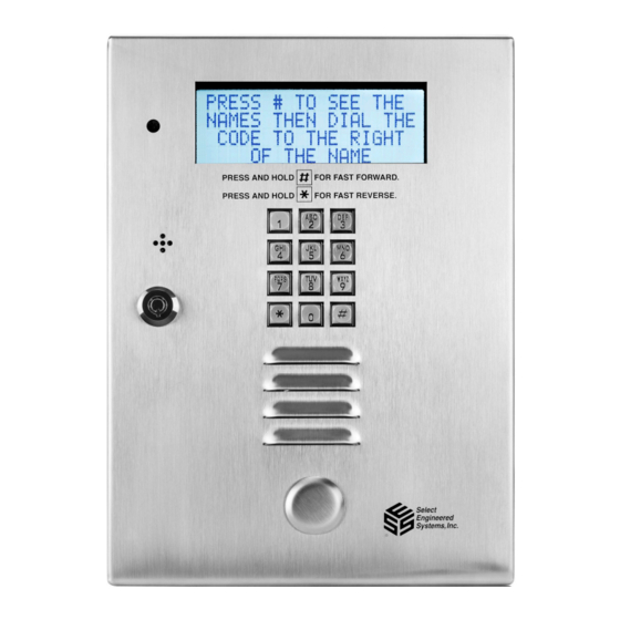
Summary of Contents for Select Engineered Systems TEC1A Series
- Page 1 INSTALLER GUIDE TEC1A SERIES Covers: T1A2LxxxBSK/DLX/PRM T1A4LxxxBSK/DLX/PRM Select Engineered Systems, Inc. 7991 West 26 Hialeah, FL 33016 Tel: 305 823 5410 Fax: 305 823 5215 www.selectses.com © 2003 – 2020 All Rights Reserved 600TEC1A_INST Jan 2020...
-
Page 2: Table Of Contents
TEC1A Installer Guide 01/20 Installation – TEC1A Series Access Controllers ............3 Safety Warnings / Avertissements de Sécurité ............ 3 1.1.1 English Language..................3 1.1.2 Sécurité Avertissements En français ............. 3 Coordination with Telephone Company .............. 4 Mechanical Mounting ..................5 1.3.1... - Page 3 TEC1A Installer Guide 01/20 Figure 1: Installation Height for Pedestrian and Drive-Up Applications ......5 Figure 2: TEC1A Location of Back Box Ground Lug ............6 Figure 3: TEC1A Ground Lug Connection ................ 7 Figure 4: Inside Door of TEC1A ..................7 Figure 5: TEC1A User Connections ...................
-
Page 4: Installation - Tec1A Series Access Controllers
TEC1A Installer Guide 01/20 1 Installation – TEC1A Series Access Controllers Safety Warnings / Avertissements de Sécurité 1.1.1 English Language For your safety please observe the following recommendations when installing TEC1A series product enclosures: Never install equipment during a lightning storm or other hazardous event ... -
Page 5: Coordination With Telephone Company
TEC1A Installer Guide 01/20 Coordination with Telephone Company Installation of TEC1A requires coordination with your telephone company. A Touch-Tone™ line is required for dialing out purposes – legacy pulse dialing is not available. The phone company may require the following information: ... -
Page 6: Mechanical Mounting
TEC1A Installer Guide 01/20 Mechanical Mounting 1.3.1 Installation Heights Figure 1 shows the recommended installation heights for TEC1A series access controllers. Figure 1: Installation Height for Pedestrian and Drive-Up Applications 1.3.2 Surface Mount Mount the back-box using the holes provided. -
Page 7: Electrical
TEC1A Installer Guide 01/20 Electrical 1.4.1 Grounding The TEC1A MUST BE AT EARTH GROUND POTENTIAL. Connect a #16 stranded or larger wire from the ground lug in the base of the back box of the TEC1A to a cold water pipe or other suitable ground. This wire should be less than 50 feet in length. -
Page 8: Overall Main Board Layout
TEC1A Installer Guide 01/20 Figure 3: TEC1A Ground Lug Connection 1.4.2 Overall Main Board Layout See Figure 4 below for an image of the main board. Comm Board Mounting Location (Add-on option) MUI Board Mounting Location (Add-on option) 2-Reader Board Location (Add-on option) User Connection Strip... -
Page 9: User Connections
TEC1A Installer Guide 01/20 1.4.3 User Connections Figure 5 shows the Terminal Strip connections P1 and P1A for user connections, along with the Door Ground Stud. No other connections are required. Figure 5: TEC1A User Connections 1.4.3.1 Telephone Connection Use the RJ-11 supplied with the flying lead to connect the TEC1A to the telephone network provided. - Page 10 TEC1A Installer Guide 01/20 The exception is when connecting additional SES access controllers. In this case, an optional MUI plug-in board must be used, allowing up to four SES Access Controllers to be connected on the same line. 1.4.3.2 TEC1A Power Power can be supplied in ONE of two ways.
-
Page 11: Option Cards
TEC1A Installer Guide 01/20 1.4.3.3 Rex (Request to Exit) Inputs The request to exit inputs (RX1 and RX2) are VOLT-FREE (dry) contacts located on connector P1 as shown in Figure 5. No external voltage is either required or desired. To use either Rex input, connect the COM (between RX1 and RX2 of connector P1) to one side of the external relay’s contact being used to request exit, then connect either RX1 or RX2 to the other side of the relay contact as desired. -
Page 12: Programming A Directory Record With A Pin Into A Tec1A
Note that Steps 4 and 5 are included to check if PINs are enabled. Once PINs are enabled, steps 4 and 5 can be skipped for future entries. For all other settings please refer to “TEC1A Series Menus”. Steps to Program a Directory Record with a PIN into a TEC1A using the Keypad...

Need help?
Do you have a question about the TEC1A Series and is the answer not in the manual?
Questions and answers