
Summary of Contents for Weber Klassik Series
- Page 1 User’s Manual Weber Klassik Series Wheel balancer Version 1.4 Status: June 2016 www.Weber-Werke.de Weber GmbH Sülzbach 1 D-37293 Herleshausen Telephone: +49 (0) 5654 / 343 Fax: +49 (0) 5654 / 794 info@Weber-Werke.de...
-
Page 2: Table Of Contents
Table of contents Safety Safety instructions Mounting Protocol for initial commissioning by a qualified technician EC - Declaration of conformity Operation and maintenance Description of the machine Technical data Unpacking Installation Electrical connection Maintenance Mounting the wheel guard Mounting the clamping shaft Operating iInstructions Display Control panel... -
Page 3: Safety
This machine must only be used for the purpose for which it was designed by the manufacturer. Any other use is not permitted. Weber GmbH is not liable for damages caused by improper use and abuse. Unauthorised interventions or modifications to the machine are not permitted. -
Page 4: Mounting
• Basic settings checked or changed • Wheel balancer calibrated No defects have been found, so there are no objections to commissioning. Weber Klassik Series Wheel balancer year of manufacture Serial no. Date of purchase _______ Dealer address Date: Signature:... -
Page 5: Ec - Declaration Of Conformity
EC Directive on the basis of its design and construction, as well as the version thereof placed on the market by Weber GmbH In the event of modifications to the machine which have not been agreed with the signatory, this declaration shall lapse. -
Page 6: Operation And Maintenance
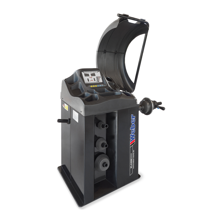
Usage & maintenance Description of the machine Machine cover with weight compartments Side panel Display with keyboard "A" Distance meter Clamping shaft Quick-release nut Chassis Technical data Max. wheel weight, kg Balancing time, sec. Power supply, V/Hz 230/50 Operating temperature, °C 0-50 Balancing functions STEEL, STATIC, MOTORCYCLE, ALU-1, ALU-... -
Page 7: Electrical Connection
The space required must be adapted to local conditions after fitting the wheel guard and tightening the clamping shaft. Avoid moving the machine by the wheel guard. This may result in damage to the guard’s bearing or to the switch mechanism. This machine must not be used in potentially explosive atmospheres. -
Page 8: Mounting The Wheel Guard
Mounting the wheel guard 1. Pull the switch cable through the connection flange for the wheel guard and connect it to the switch (Fig. 1). Then screw the connecting flange to the machine using the 3 screws provided. 2. Screw the wheel guard together in the middle (Fig. 2) and click it on the corresponding frame. -
Page 9: Operating Iinstructions
Operating instructions Display Digital display for displaying the internal imbalance value. Indicators for determining the internal imbalance position. Digital display for displaying the external imbalance value. Indicators for determining the external imbalance position. Display of the balancing mode - 9 -... -
Page 10: Control Panel
Control panel Minus button to decrease the value for the distance to the machine. Plus button to increase the value for the distance to the machine. Minus button to decrease the rim width value. Plus button to increase the rim width value. Minus button to decrease the value for the rim diameter. -
Page 11: Wheel Clamping
Clamping a wheel There are two different methods for wheel clamping. Clamping method 1 - clamping cone on the rear of the rim Most steel wheels can be mounted correctly using this method. The wheel is centered on a cone on the inside of the hub. -
Page 12: Correct Handling Of The Clamping Shaft And Quick-Release Nut
Correct handling of the quick-release nut and balance shaft Note: Incorrect use of the quick-release nut or incorrect clamping and removal of the wheel can damage the quick-release nut and the clamping shaft. The manufacturer/importer/seller is not liable for damage caused by improper use. This damage is not covered by the warranty. -
Page 13: Working With The Wheel Balancer
Working with the wheel balancer The main switch is located on the left side of the machine chassis. A self-test is carried out during operation. A sequence of numbers appears on the display and after a few seconds the display shows "a" and "8.0. Clamp the clean wheel onto the clamping shaft using the correct centering cone. - Page 14 Press the diameter determination buttons "d+" or "d-" to enter the diameter indicated on the rim and tyre. The left-hand display shows "d", the right-hand display shows the value entered. Close the wheel guard and balancing begins. If button "1" is pressed while the wheel guard is open, "ERR-5"...
-
Page 15: Self Calibration
Self-calibration of the machine Before commissioning and at regular intervals, depending on the frequency of use, a self- calibration must be carried out. A monthly self-calibration cycle is recommended for normal workshop use. This ensures that the measurement results are correct. 1. -
Page 16: Balancing Programs
Balancing programs The balancing programs must be selected by pressing the button next to the programs. Standard program Active without display in switch-on mode Balancing steel or alloy wheels using balancing weights at the rim edges. Static program The STATIC correction is used for motorcycle wheels and for wheels on which a weight does not have to be applied on both sides of the rim. -
Page 17: Standard Accessories
Included standard accessories Included in the delivery: Wheel balancer incl. wheel guard and balancing shaft Calibration weight, rim width gauge, weight rod, weight rod, 4 balancing cones, quick-release nut, alloy rim adapter for quick- release nut Installation and operating instructions -17 -... -
Page 18: Errors And Diagnostics
Malfunctions: diagnosis & troubleshooting Symptom Cause Solution No signal on the display 1. Power supply failure. 1. Check the external after switching on. 2. The machine power power supply. supply unit is 2. Replace the power supply defective. unit. 3. Incorrect connection 3.
Need help?
Do you have a question about the Klassik Series and is the answer not in the manual?
Questions and answers