Advertisement
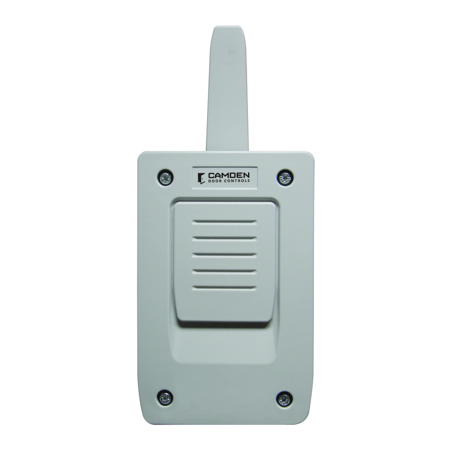
CV-WRX4
Wiegand Receiver
INSTALLATION INSTRUCTIONS
THIS PACKAGE INCLUDES:
(1) CV-WRX4 Receiver
(2) #6 x 1-1/4" Screws
1. TECHNICAL CHARACTERISTICS
Power Supply
12V DC ( 9VDC - 21VDC)
Frequency
868.35 MHz
Consumption
14mA / 36mA
Standby / Operating
Operating
-4°F to +185°F (-20°C to +85°C)
Temperature
IP Rating
IP54 (IP65 with cable plug installed)
3 1/4" W x 7 3/8" H x 1 5/8" D
Dimensions
(82mm x 187mm x 42mm)
2. INSTALLATION AND CONNECTIONS
Attach the rear part of the enclosure to the wall using the
plugs and screws supplied. Pass the cables through the
grommet of the enclosure. Connect the power cables to the
terminals marked on the mother board, as Indicated.
Mount the receiver cover and pass the cables and the
antenna through it.
(2) #6 Wall Plugs
(1) Cable Plug
CV-WRX4 receiver is designed for use with Camden
CV-WTX2 transmitters. The transmitter signal is codified in two
different protocols according to its configuration: Wiegand 26
and Wiegand 37. The receiver provides facility codes 1 to 255
by DIP switch J9 using 8 bit binary configuration.
ON
1
2
3
128
64 32
MSB
J9
+
12V dc supply
-
12V dc supply
3. OPERATING
Configuration and connection for the different protocols.
Protocol
Wiegand
26
Wiegand
37
Note: To use other protocols, contact Camden.
Operations
The green power on LED will illuminate when power is
provided. The red signal LED will illuminate for the duration it
receives the message from the transmitter.
If the red LED does not illuminate when the transmitter
button is pressed, the receiver is not receiving the
transmission signal from the transmitter. Reduce the distance
to the receiver, and verify the transmitter is working as
suggested
Refer to Facility Code DIP switch table to select the value of
facility code to be sent from the receiver.
The DIP switch positions set
the facility code.
The DIP switch positions will provide a
facility code = 34. SW#3 = 32. SW#7 =2.
For example:
The total = 32 + 2 = 34
34. SW#3 = 32. SW#7 = 2.
4
5
6
7
8
The total = 32 + 2 = 34
16
8
4
2
1
LSB
CH1
Decoded signal output (D0 Wiegand)
Decoded signal output (D1 Wiegand)
CH2
Decoded signal output (D0 Wiegand)
Decoded signal output (D1 Wiegand)
Power
Signal
SW1
Supply
Outlet
Protocol
D0 and
+ -
Off
D1
D0 and
+ -
ON
D1
Format
8 bits facility code + 16 bits
credential ID number
-
Page 1 of 2
Advertisement
Table of Contents

Subscribe to Our Youtube Channel
Summary of Contents for CAMDEN CV-WRX4
- Page 1 (2) #6 Wall Plugs (2) #6 x 1-1/4" Screws (1) Cable Plug CV-WRX4 receiver is designed for use with Camden CV-WTX2 transmitters. The transmitter signal is codified in two different protocols according to its configuration: Wiegand 26 and Wiegand 37. The receiver provides facility codes 1 to 255 by DIP switch J9 using 8 bit binary configuration.
- Page 2 • This equipment is designed for use as a remote control for overhead doors and access control. Its use is not guaranteed for directly activating any other equipment different to that specified. • Camden reserves the right to modify equipment specifications without prior notice. COMPLIANCE This device complies with Part 15 of the FCC Rules and Industry Canada licence-exempt RSS standard(s).


Need help?
Do you have a question about the CV-WRX4 and is the answer not in the manual?
Questions and answers