Table of Contents
Advertisement
Section 1
General Description
Camden Lazerpoint™ Radio Controls comprise the following
models:
CM-TX-9 Wall switch ready transmitter
CM-RX-91 Basic Receiver
CM-RX-92 Full function (dual relay) Receiver.
This instruction manual covers the TX-9 and RX-92 models
as well as the plug-in daughterboard's, and related
Camden Lazerpoint™ RF is the first system designed to
address the specific needs of the Automatic Door industry.
Unlike typical "garage door" RF, Camden's Lazerpoint™
operates at 915 MHz frequency to "cut through" the noise
and clutter, and penetrate typical building materials to
ensure a reliable installation every time.
TX-9 transmitters utilize readily available AAA batteries,
and special circuitry assures long life. A proprietary piezo
sounder is used to annunciate low battery, battery level,
and "stuck switch" conditions.
Two receiver models are offered – the basic single relay
RX-91, and the full function RX-92. The RX-92 offers 6
operating modes including dual independent channels,
latching, and bi-directional sequencing.
Both receivers can be fitted with plug-in daughterboard's
ensuring compatibility with older RF technologies. Up to two
such boards may be installed at one time, simultaneously
allowing the receiver to work with three different frequencies
– another Camden exclusive.
Both receiver models feature convenient terminal strip
Connections, visual signal strength indicators, and 40 code
memory with push-and-learn technology.
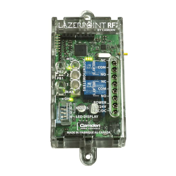
Lazerpoint™ RF RX-92
Full-Function Receiver
Installation Instructions
Section 2
Installation
Mounting
The TX-9 is designed to mount behind a switch in a wall-
box, post, or other suitable enclosure. Double sided tape is
used to attach the circuit board and battery holder securely
to the enclosure. Even though the circuit board is conformal
coated, care should be taken to ensure the transmitter does
not get wet.
The RX-92 receiver is designed to mount inside the automatic
door header. Screw holes are located at each end of the
receiver case, or the included velcro may also be used to
hold it securely.
For Dimensional information refer to RX-92 Electrical and
Mechanical Drawing on Page 5.
Wiring
Wiring of this unit is dependant on the application and mode.
Determine the appropriate mode, and then proceed to the
section and drawing indicated.
Note: Do not use the Lazerpoint RF system as a Safety
device!!. If safety devices are used, always wire them directly
to the operator control box.
Section 3
Set-up Instructions
The RX-92 has two relays, and three potentiometers with two
1 – 30 second adjustable Hold time (or delay-on-release)
and a 1 – 15 second delay-on-activate for the second relay.
The 4-position dip switch selects from one of 6 different
operating modes.
Dip switch #4 controls the display of LED 1 & LED 2. When
set to OFF, it will display the operation of the associated
relay(s). When set to ON, it will blink a count to indicate the
received signal strength. To facilitate set-up, set to OFF.
Page 1 of 13
Advertisement
Table of Contents

Related Manuals for CAMDEN Lazerpoint RF RX-92


Summary of Contents for CAMDEN Lazerpoint RF RX-92
-
Page 1: Installation Instructions
Camden Lazerpoint™ RF is the first system designed to address the specific needs of the Automatic Door industry. For Dimensional information refer to RX-92 Electrical and Unlike typical “garage door”... - Page 2 Lazerpoint™ RF RX-92 Full-Function Receiver Installation Instructions should now make a distinctive hi-low sound. This signal will Step 1 sound for 6 seconds, then turn off for a minute, then sound Select Operating Mode again. This is the “stuck switch indicator” feature. Repeat for Select the desired operating mode by setting the first 3 additional transmitters.
- Page 3 Pairs of LED’s mounted on both sides of the cable increase visibility. A unique feature of Camden’s Lazerpoint RF is the ability to add one or two daughterboard’s, extending compatibility Display status is dependant on Dip switch 4 setting. Turn OFF to older technologies.
- Page 4 (at our discretion) without charge. Operating voltage 12 / 24 Volts, AC / DC Except as stated herein, Camden extends no warranties Current Draw 23 mA nominal @ 24 VAC expressed or implied regarding function, performance or 63 mA maximum @ 24 VAC service.
- Page 5 Page 5 of 13...
- Page 6 Page 6 of 13...
- Page 7 Page 7 of 13...
- Page 8 Page 8 of 13...
- Page 9 Page 9 of 13...
- Page 10 Page 10 of 13...
- Page 11 Page 11 of 13...
- Page 12 Page 12 of 13...
- Page 13 —Connect the equipment into an outlet on a circuit different from that to which the receiver is connected. —Consult the dealer or an experienced radio/TV technician for help. Changes or modifications made to this equipment not expressly approved by Camden Door Control could void the user’s authority to operate the equipment. Push Buttons...