Table of Contents
Advertisement
Quick Links
Advertisement
Table of Contents

Related Manuals for GOG G-1


Summary of Contents for GOG G-1
- Page 1 Operation and adjustment instructions...
-
Page 2: Quick Start
300 feet per second). Depending on what modes of fire are allowed at the field where you are playing (semi-automatic, rebound, etc.) you may need to adjust the G-1 ’s firing mode. See the Electronic Adjustment section for more information. -
Page 3: Table Of Contents
Flashlight Mounting MARKER. • KEEP YOUR FINGER OFF THE TRIGGER UNTIL Firing Modes / Dwell READY TO SHOOT. NEVER POINT THE G-1 Unloading / De-Gassing ANYTHING YOU DON’T INTEND TO SHOOT. • KEEP THE G-1 ON SAFE (POWER OFF) UNTIL Field Stripping READY TO SHOOT (SEE QUICK START). -
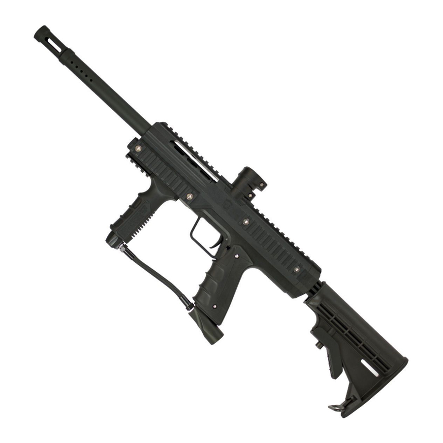
Page 4: Getting Familiar
This DOES NOT mean that you should neglect your G-1 . If PROPELLANT: or Nitrogen/Compressed air you take care of it off the field, your G-1 RATE OF FIRE: 11 bps will take care of you on the field. For best OPERATION:... -
Page 5: Barrel Blocker / Hopper
Its low-force bolt will often prevent paintballs from being chopped if the hopper is not able to load paintballs as fast as the G-1 being fired. If you want to realize the G-1 ’s maximum firepower potential, especially if it is upgraded... -
Page 6: Gasses
Always turn-on or screw-in a compressed air system or CO slowly, so that the valve opens slowly, and the gas pressure inside the marker is raised smoothly. Be gentle to the internals of your G-1 and they will reward you with a long service life. - Page 7 J-shaped tube that draws gaseous CO from the top of the tank when it is in a horizontal position. Anti-siphon tubes must be professionally installed, to ensure that critical safety checks are performed during valve installation. If using an anti-siphon tank, the G-1 ’s IMPORTANT stock bottom-line ASA fitting should be replaced with an ASA that will place the tank completely hori- zontal.
-
Page 8: Battery
The G-1 is powered by a standard 9-volt alkaline battery. Lower cost “heavy duty” batteries will not consistently deliver the amperage needed to operate the G-1 . Erratic performance, especially drops in velocity or skipped shots during rapid fire can result from a battery that is not delivering full power. -
Page 9: Paint
If velocity adjustment is necessary, Use a 5/32-inch allen wrench on the adjuster in the bottom of the vertical regulator, turn clockwise to increase the velocity/pressure, and counter-clockwise to decrease. Take three or four shots after every adjustment to allow the gas pressure inside the G-1 to stabilize. -
Page 10: Trigger Adjustment
FIG. 8 TRIGGER ADJUSTMENT The length of the G-1 trigger pull is adjustable with a 1/8-inch allen wrench. The trigger adjustment screw is located at the bottom of the trigger guard where it meets the grip frame. It may be helpful to remove the marker’s rubber grips to provide easier access when making adjustments. -
Page 11: Flashlight Mounting
FLA S HLIGH T MOU NT I NG FIG. 9 FLASHLIGHT PLUG In addition to accessories that can be mounted on its Picatiny tactical rails, the G-1 features an integrated flashlight mount. Using this mount, a compatible 2-Cell AA Mini Maglite flashlight can be ®... -
Page 12: Firing Modes / Dwell
. If you intend to use HPA, you must change your dwell mode in order to achieve best gas efficiency and battery life. With the marker unloaded and de-gassed, remove and unplug the 9-volt alkaline battery. Plug the battery back in while holding the power button down. The G-1 will indicate that it has changed to HPA mode by double-blinking the power button LED and turning off. -
Page 13: Unloading / De-Gassing
BEFORE PERFORMING MAINTENANCE PROCEDURES. Dry-fire 2 or 3 shots in a safe direction to ensure that no paintballs remain in the G-1 Continue to dry fire the G-1 in a safe direction while turning off or unscrewing the HPA system or CO tank, until all of the gas pressure inside has been released. -
Page 14: Field Stripping
Slide the bolt stop onto the bolt from the rear. Slide the rear of the bolt into the bolt sleeve. Hold this entire assembly vertically with the front of the bolt pointing upward, and insert it up into the back of the G-1 . -
Page 15: Advanced Maintenance
Reach the long end of a 1/8-inch allen wrench through the access hole in the top tactical rail, down into the head of the vertical ASA screw. Unscrew the the two gas-through banjo bolts (indicated with arrows in Figure 15) using a 1/8-inch allen wrench. If the G-1... -
Page 16: Feedneck Position
Both rubber ball detents should extend into the breech and show no rips or tears. If they must be replaced, they may be pried out with an o-ring pick, and pressed into place with a small allen wrench. If the G-1 has been upgraded with a circuit board featuring an anti-chop eye, holding the breech and receiver upside down will help the anti-chop circuit board remain seated while the parts are being reassembled. - Page 17 To change the side from which the G-1 feeds, the marker must be disassembled and the breech removed from the receiver, following the directions for advanced maintenance.
-
Page 18: Vertical Regulator
FIG. 19 REGULATOR DISASSEMBLY REGULATOR SERVICE Although explained here, regulator service should only be performed by a GOG Paintball trained airsmith. With the marker unloaded and de-gassed, remove the lower tactical rail as when installing a flashlight (see flashlight section of this manual). Unscrew the regulator from the marker and remove the grip frame following the instructions in this manual. - Page 19 EQUIPMENT FAILURE OR INJURY AND sure to inspect, and if necessary, replace the inlet filter in the side of the velocity adjuster. INVALIDATING THE GOG PAINTBALL WARRANTY. The vertical regulator is reassembled in the reverse order of disassembly. The piston slides into the regulator body wide end first, followed by the regulator spring.
-
Page 20: Troubleshooting / Warranty
• Pneumatic hoses may be loose, damaged or not fully connected. Replace hoses with genuine GOG Paintball hoses only. • Hose has been disconnected and re-attached. Replace with a new GOG Paintball internal hose. Removing a hose streches it so that it cannot be re-used without leaking. MARKER IS LEAKING DOWN THE BARREL •... - Page 21 • Battery may be low. This will be most noticeable with velocity dropping and then entire shots not firing during rapid fire. Replace battery with a new name brand alkaline battery. • Regulator may be contaminated or damaged. Follow the instructions in this manual or see a GOG Paintball technician for service. • Liquid CO may be entering the regulator –...
- Page 22 See the trigger adjustment section of this manual for guidance. Additional support and downloadable product • Trigger switch may be damaged. Contact your dealer or GOG Paintball technical manuals are available through our website at support.
-
Page 23: Parts Diagrams
P ART S DIA G RAMS G-11105 G-1 REGULATOR COVER OM7014 - PISTON O-RING VRG105 - REGULATOR PISTON REGULATOR SSS011 - VRG106 - REGULATOR SEAL PISTON REG COVER LOCKING SCREW SPR032 - REGULATOR SPRING OM7014 - SPRING PLATFORM O-RING OB9015 - REGULATOR... - Page 24 P ART S DIA G RAMS BOLT ASSEMBLY BOLT SLEEVE ASSEMBLY BREECH ASSEMBLY BOLT STOP ASSEMBLY G-1120 G-1119 G-1121 SSB003 PIN020 GOGpaintball.com...
- Page 25 P ART S DIA G RAMS ENV104 OB7018 OB7022 G-1102 XTC110 OB7018 OB9017 OU7010 OH7017 OB7018 XTC109 OU7014 OH7M10 OU9015 GOGpaintball.com...
- Page 26 P ART S DIA G RAMS BODY ASSEMBLY STOCK ADAPTER STOCK ASSEMBLY SOL302ASM GRIP FRAME ASSEMBLY SSB003 SSB003 ENV136 HBR603 - BOTTOM LINE HOSE GOGpaintball.com...
- Page 27 P ART S DIA G RAMS G-1 TRIGGER ASSEMBLY SP1107ASMBLK MAGNET SITS FLUSH WITH THIS EDGE G1107 - G-1 SINGLE FINGER TRIGGER MAG003 - TRIGGER MAGNET WHEN INSTALLING POWER BUTTON BE SURE THE LINE IN THE SYMBOL SOS010 IS POINTING UP...
- Page 28 P ART S DIA G RAMS ENV111 G-1102 ELB001 ENV111 G-1114 NUT003 NUT003 SSC008 G-1101 SSC008 G-1115 G-1113 G-1112 SSF004 G-1123 OB7016 PIN019 G-1125 SSF004 GOGpaintball.com...
- Page 29 Manual V1.01 © Copyright 2010, GOG Paintball, SA, all rights reserved. GOGpaintball.com GOGpaintball.com G-1, GR33SE, GOG, GOG Paintball and the GOG Paintball logos are trademarks or registered trademarks of GOG Paintball, SA.
Need help?
Do you have a question about the G-1 and is the answer not in the manual?
Questions and answers