
Subscribe to Our Youtube Channel
Related Manuals for Peak PCAN-Router Pro FD


Summary of Contents for Peak PCAN-Router Pro FD
- Page 1 PCAN-Router Pro FD 6-Channel CAN FD Router with I/O and Data Logger User Manual Document version 1.5.1 (2021-06-29)
- Page 2 © 2021 PEAK-System Technik GmbH Duplication (copying, printing, or other forms) and the electronic distribution of this document is only allowed with explicit permission of PEAK-System Technik GmbH. PEAK-System Technik GmbH reserves the right to change technical data without prior announcement. The general business conditions and the regulations of the license agreement apply.
-
Page 3: Table Of Contents
PCAN-Router Pro FD – User Manual Contents Introduction Properties at a Glance Operation Requirements Scope of Supply Connectors and Operating Elements Power Supply CAN Connection Inputs and Outputs (I/O) USB Connection SD Card Slot and Internal Memory Log Off Card Button... - Page 4 PCAN-Router Pro FD – User Manual Firmware Upload System Requirements Preparing the Hardware Firmware Transfer Configurable Data Logging Installation Configuration 7.2.1 Nominal and Data Bit Rates 7.2.2 CAN Specification and Options 7.2.3 Trace Options 7.2.4 Maximum File Size 7.2.5 Trace Mode 7.2.6...
- Page 5 PCAN-Router Pro FD – User Manual Technical Specifications Appendix A CE Certificate Appendix B Dimension Drawing Appendix C Disposal Information (Battery)
-
Page 6: Introduction
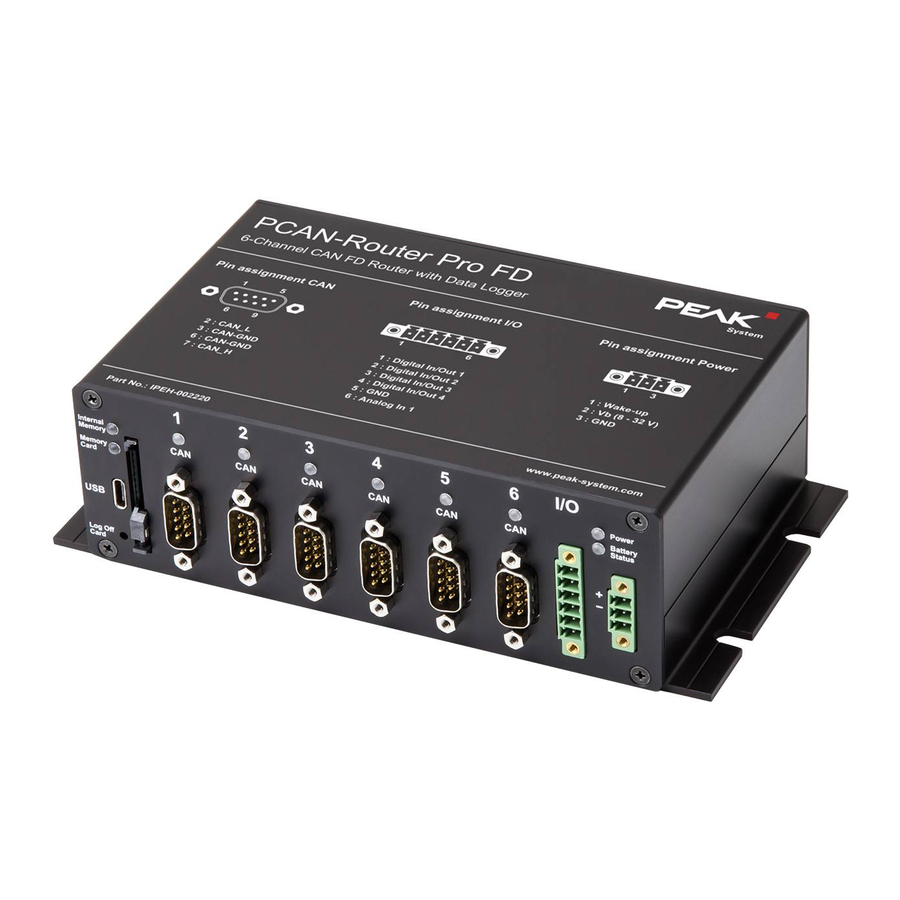
PCAN-Router Pro FD – User Manual Introduction With six channels, the PCAN-Router Pro FD links the data traffic of modern CAN FD and classic CAN buses. Pluggable CAN transceiver modules allow flexible adaptation of each CAN channel to the respective requirements. In addition, the router is equipped with an analog input and four digital I/Os. - Page 7 PCAN-Router Pro FD – User Manual • NXP CAN transceiver TJA1043 with Wake-up • Alternative pluggable transceiver modules on request (details on page 16) CAN connections are D-Sub, 9-pin CAN termination switchable, separately for each CAN channel Wake-up function using separate input, CAN bus, or real-time...
-
Page 8: Operation Requirements
(-40 to 185 °F) Operation Requirements Power supply in the range of 8 to 32 V DC The transfer of the firmware via CAN requires a PEAK CAN interface Scope of Supply PCAN-Router Pro FD in aluminum casing including mating... -
Page 9: Connectors And Operating Elements
PCAN-Router Pro FD – User Manual Connectors and Operating Elements This chapter describes the connectors on the front and rear panel of the PCAN-Router Pro FD. Figure 1: Connectors on the front panel of the PCAN-Router Pro FD Figure 2: Description of the pin assignments... -
Page 10: Power Supply
PCAN-Router Pro FD – User Manual Power Supply For the operation of the PCAN-Router Pro FD a voltage source with nominal 12 V DC is required, 8 to 32 V are possible. The input is electronically protected with reverse polarity and overvoltage protection. -
Page 11: Inputs And Outputs (I/O)
PCAN-Router Pro FD – User Manual Figure 4: Pin assignment High-speed CAN Inputs and Outputs (I/O) The I/O connector has 4 digital inputs and outputs and one analog input. The connection is made via the supplied mating connector (6-pin, type: Phoenix Contact MC1,5/6-STF-3,81), to which you can screw cable strands. -
Page 12: Usb Connection
Note: Access to the USB connection via the CPU is not possible. SD Card Slot and Internal Memory The PCAN-Router Pro FD is equipped with an internal memory card. Optionally, an additional SD card can be inserted into the SD card slot. -
Page 13: Id Rotary Switch
PCAN-Router Pro FD – User Manual ID Rotary Switch On the back of the PCAN-Router Pro FD housing is a rotary switch for selecting an ID from 0 to F. The selected value can be read out with a custom firmware. -
Page 14: Ethernet Connection
PCAN-Router Pro FD – User Manual Ethernet Connection Optionally, the PCAN-Router Pro FD is available with an Ethernet interface (IPEH-002222). The connection is established via an RJ-45 socket on the back of the housing. Figure 7: Back side of product version with Ethernet interface (IPEH-002222) -
Page 15: Operation
Operation Ensuring Power Supply The PCAN-Router Pro FD must be supplied with a nominal 12 V DC voltage (8 to 32 V possible) via the power connector. Note: If you install a backup battery (see section 4.4) and it is charged, the device can also be operated without a power supply (e.g. -
Page 16: Hardware Modifications
PCAN-Router Pro FD – User Manual Hardware Modifications You can do various hardware modifications on the board of the PCAN-Router Pro FD: Using an alternative CAN transceiver module (section 4.1) Adapting the termination for a CAN bus (section 4.2) Changing the button cell for the real-time clock (section 4.3) - Page 17 PCAN-Router Pro FD – User Manual Figure 8: Positions of the transceiver modules for the six CAN FD channels Attention! Electrostatic discharge (ESD) can damage or destroy components on the card. Take precautions to avoid ESD. Do the following to change a transceiver module: Disconnect the device from the power supply.
-
Page 18: Setting The Termination For A Can Bus
PCAN-Router Pro FD – User Manual If the PCAN-Router Pro FD is restarted, it automatically detects the type of the installed CAN transceiver module and sets the transmission standard (see table above) for the CAN channel accordingly. Note: If one or more transceiver modules without wake-up function are installed, an external wake-up signal via pin 1 of the power connector is required. -
Page 19: Changing The Button Cell For The Real-Time Clock (Rtc)
Changing the Button Cell for the Real- Time Clock (RTC) The real-time clock (RTC) installed in the PCAN-Router Pro FD is supplied by a button cell of the IEC type CR1620 (3 V) as long as the device is switched off (without power supply). - Page 20 PCAN-Router Pro FD – User Manual Figure 10: Position of the button cell for the real-time clock on the main board A new button cell lasts several years. If the internal clock indicates an unexpected time, remove the button cell, and measure its vol- tage.
-
Page 21: Installing Backup Battery
Fasten the four screws to the front and rear of the housing. Installing Backup Battery On the board of the PCAN-Router Pro FD a backup battery in the form factor 18650 can be inserted, which must be protected against short circuit, overcharging, and deep discharge (Protection PCB). - Page 22 PCAN-Router Pro FD – User Manual Attention! Electrostatic discharge (ESD) can damage or destroy components on the card. Take precautions to avoid ESD. Do the following to install the backup battery: Disconnect the device from the power supply. Remove the eight screws at the front and rear of the housing.
-
Page 23: Creating Own Firmware
PCAN-Router Pro FD – User Manual Creating Own Firmware With the help of the development package, you can program your own application-specific firmware for PEAK-System programmable hardware products. Download of the development package: URL: www.peak-system.com/quick/DLP-DevPack System Requirements: PC with Windows 10, 8.1 (32-/64-bit) - Page 24 PCAN-Router Pro FD – User Manual SetPath_for_VSCode.vbs VBScript to modify the example directories for the Visual Studio Code IDE. Do the following to create your own firmware: Create a folder on your PC. We recommend using a local drive. Unzip the development package PEAK-DevPack.zip completely into your folder.
-
Page 25: Firmware Upload
The firmware upload is done via a CAN bus with the supplied Windows program PEAK-Flash. System Requirements In order to upload a new firmware to the PCAN-Router Pro FD, the following requirements must be met: CAN interface of the PCAN series for the computer (e.g. - Page 26 PCAN-Router Pro FD – User Manual Do the following to start the bootloader with the Log Off Card button: Figure 12: Log Off Card button on the bottom left of the front Disconnect the power supply. Press and hold the Log Off Card button and restore the power supply.
- Page 27 PCAN-Router Pro FD – User Manual Do the following to start the bootloader with the rotary switch: Figure 13: ID rotary switch on the back Turn the ID rotary switch on the back of the housing to position F. Use a slotted screwdriver, for example.
-
Page 28: Firmware Transfer
The selected CAN channel must be connected alone to the PC. Firmware Transfer Do the following to transfer a new firmware with PEAK-Flash The software PEAK-Flash is included in the development package, which can be downloaded via the following link: www.peak-system.com/quick/DLP-DevPack... - Page 29 500 kbit/s from the Bit rate drop-down menu. Figure 16: Hardware selection Click on Detect. In the list, the PCAN-Router Pro FD appears together with its Module ID and Firmware version. With the triangle on the left of the name you can reveal details about your hardware.
- Page 30 15. If you have activated the bootloader with the rotary switch, turn it back to the previously set module ID. 16. Restart the device by interrupting the power supply. You can now use the PCAN-Router Pro FD with the new firmware.
-
Page 31: Configurable Data Logging
PCAN-Router Pro FD – User Manual Configurable Data Logging In addition to the programming examples, the PCAN-Router Pro FD is delivered with a ready-to-use firmware for tracing CAN data. The CAN messages can be recorded on the internal eMMC memory or on an inserted SD card which are both accessible via the USB connector. -
Page 32: Installation
JSON format (example website included in the development package) Note: When using the firmware for data logging, the other programmable features of the PCAN-Router Pro FD are not available. Installation Important note for devices with a serial number up to 150: The development package contains various upgrades in the directory \Hardware\PCAN-Router Pro FD\Upgrades\. -
Page 33: Configuration
PCAN-Router Pro FD – User Manual The firmware file (*.bin) is in the directory \Hardware\PCAN-Router Pro FD\Datalogger\. Proceed with the firmware upload as described in chapter 6 Firmware Upload on page 25. After a successful upload, proceed with the configuration described in the next chapter. -
Page 34: Nominal And Data Bit Rates
PCAN-Router Pro FD – User Manual If parameters are not specified, default values are used, if available In case of an error, parsing is stopped and the Status LED is blinking red quickly After editing, the file can be uploaded to a memory card via USB. -
Page 35: Can Specification And Options
PCAN-Router Pro FD – User Manual Parameter Value Range Description nom_tseg2 1 to 128 Time Segment 2 of the nominal bit rate. nom_sjw 1 to 128 Synchronization Jump Width of the nominal bit rate. data_brp 1 to 1024 Bit Rate Prescaler of the data bit rate. -
Page 36: Trace Options
PCAN-Router Pro FD – User Manual Option Description pflash7E7 This option enables a firmware update via PEAK-Flash without turning the rotary switch on the rear of the housing to F. In this case the new firmware is transferred to the device using CAN messages with the ID 7E7. -
Page 37: Trace Mode
PCAN-Router Pro FD – User Manual Tip: Using the software PEAK-Converter, trace files can be converted into other formats and single channels can be extracted. The PEAK-Converter can be downloaded for free from our website www.peak-system.com/quick/DL-Software-E. 7.2.5 Trace Mode In this section, the trace mode is configured. This covers handling of existing files when a new recording is started and the behavior if the memory's maximum capacity is reached. -
Page 38: Handling Of The Usb Connection
PCAN-Router Pro FD – User Manual TRC_DRIVE=EMMC Option Description The optional insertable SD card is used for tracing. EMMC The internal eMMC memory card is used for tracing. This value is the default setting. 7.2.7 Handling of the USB Connection This setting specifies how an existing USB connection is handled when tracing is started. -
Page 39: Timeouts
PCAN-Router Pro FD – User Manual Option Description STOP Tracing is started by pressing the Log Off Card button or by transmitting a specific CAN message. 7.2.9 Timeouts With these settings timeouts are specified in milliseconds. No CAN traffic TRC_STOP_TRAFFIC_TO specifies a timeout for no CAN traffic. If no CAN message was received for this duration, tracing is stopped. -
Page 40: Beep Patterns
PCAN-Router Pro FD – User Manual Value Range Description 1 to 4000000000 Tracing is stopped after this duration. !1 to !4000000000 By adding ! the device is shut down after the specified duration. 7.2.10 Beep Patterns With these settings beep patterns for the events trace start, stop, and error are specified. -
Page 41: Led Blinking Patterns
PCAN-Router Pro FD – User Manual TRC_ERROR_BEEP defines a beep pattern for the event trace error which occurs if the file system of the memory card is not valid. TRC_ERROR_BEEP=1 80 x__x__x__xxx__xxx__xxx__x__x__x 7.2.11 LED Blinking Patterns The memory card LEDs are blinking if tracing is started and the cards are accessed. -
Page 42: Configuration Of The Ethernet Connection
Router Pro FD with Ethernet interface (IPEH-002222). For the configuration of the interface and its usage the config.txt has been extended. The additional settings are described in the following subchapters. Note: When using a regular PCAN-Router Pro FD without Ethernet, the additional settings are ignored. 7.3.1 IP Address This setting controls the activation of the Ethernet interface and the assignment of the IP address. -
Page 43: Subnet Mask
PCAN-Router Pro FD – User Manual Option Description DHCP Activates the Ethernet interface. The IP address, subnet mask, and gateway IP address are assigned automatically via DHCP (Dynamic Host Configuration Protocol). xxx.xxx.xxx.xxx Activates the Ethernet interface. The IP address is set manually to the specified value. -
Page 44: Gateway Address
PCAN-Router Pro FD – User Manual with the number “1”. The resulting values for the individual fields are: 0, 128, 192, 224, 240, 248, 252, 254, and 255. While entering values from left to right, as soon as a value smaller than “255”... -
Page 45: Ftp Access
Figure 18: PCAN-View Receive / Transmit window with decimal data indication The CAN message and its data can be displayed using a PEAK CAN interface and the free Windows software PCAN-View. After connecting to the CAN bus, the software lists all CAN messages and provides an option to show the data bytes in decimal format. -
Page 46: Ftp Connection Timeout
PCAN-Router Pro FD – User Manual The data transfer with FTP is described in detail in chapter 7.4.5 on page 49. 7.3.6 FTP Connection Timeout With this setting a timeout for the FTP connection is specified in seconds. If the FTP connection is idle for the set time, the connection is closed automatically. -
Page 47: Operation
PCAN-Router Pro FD – User Manual Operation 7.4.1 LEDs Figure 19: Status, CAN channel, and memory card LEDs on the front panel of the PCAN-Router Pro FD Status LED Status Description Green blinking Normal operation Red quick blinking Configuration The configuration file is not valid. Parsing error was stopped. -
Page 48: Control With The Log Off Card Button
If trace files are removed from the memory card, this *.next file must be removed too. Tip: Using the software PEAK-Converter, trace files can be converted into other formats and single channels can be extracted. -
Page 49: Memory Card Capacity And Logging Duration
Meet the following requirements: • Data logger configuration file with valid IP settings and FTP_ACCESS set to YES. • PCAN-Router Pro FD is powered and connected to the IP network via Ethernet. • Tracing is stopped. • Your FTP software is limited to a single FTP connection. - Page 50 PCAN-Router Pro FD – User Manual Figure 20: FTP connection details with example IP address Enter the IP address of your PCAN-Router Pro FD. Keep the port input free since the standard FTP port is used. Enter “anonymous” as username.
-
Page 51: Websocket Remote Control
80 is used. Example: ws://192.168.144.150 After connecting, several commands requests can be transmitted from client to PCAN-Router Pro FD. The request as well as the response messages are in JSON format. WebSocket can optionally differentiate whether different protocols are transmitted. - Page 52 PCAN-Router Pro FD – User Manual Command List All following commands require an established WebSocket connection. In case of an error, a response with cmd-err and a corresponding error message is returned. Error: {"cmd-err": "command not evaluated"} System Information This command returns system information like the part number,...
- Page 53 PCAN-Router Pro FD – User Manual Request: {"sys-cmd-exec": "hw-reboot", "time": "4000"} Response: {"cmd-info": "reboot in 4000 ms"} Errors: {"cmd-err": "reboot aborted, tracer running"} Note: It is not recommended to reboot during an FTP data transmission. Set RTC Time This command is used to set the internal RTC to a user specific time according to the UTC time format.
- Page 54 PCAN-Router Pro FD – User Manual Start the tracer: Request: {"trc-cmd-exec": "start"} Response: {"trc-status": "recording"} Errors: {"cmd-err": "tracer not started, maybe still recording"} Stop the tracer: Request: {"trc-cmd-exec": "stop"} Response: {"trc-status": "stopped"} Errors: {"cmd-err": "tracer not stopped, maybe still stopped"}...
- Page 55 Figure 21: WebSocket Remote Control example website Do the following to use the WebSocket example: Make sure that the PCAN-Router Pro FD is connected to your IP network and has a valid IP address. Open website.html with a common browser from the directory \Hardware\PCAN-Router Pro FD\ Datalogger\WebSocket_Remote_Control.
- Page 56 Use “Disconnect” to close the connection. As long as the PCAN-Router Pro FD is running, the connection is active. The connection is closed automatically if the device is disconnected or switched off. This can be used to monitor the “alive”...
- Page 57 PCAN-Router Pro FD – User Manual Technical Specifications Connectors 6 x D-Sub (m), 9 pins, assignment according to ® specification CiA 303-1 USB port type C, Superspeed USB 3.0 Upstream Inputs/outputs Phoenix mating connector MC1,5/6-STF-3,81, 6-pin; 2 x digital input or output with high-side switch...
- Page 58 PCAN-Router Pro FD – User Manual Analog Inputs Count Connectors Analog In 1 Resolution A/D converter 12 bit Input voltage maximum + 32 V Input impedance 222 kΩ Measuring range 0 – 32 V Measurement resolution 8 mV (per LSB) Measurement accuracy ±...
- Page 59 PCAN-Router Pro FD – User Manual Digital Outputs High-side Low-side Maximum output current 0.7 A minimal 1.2 A minimal (current limitation) 1.5 A typically 1.8 A typically 2.4 A maximum 3 A maximum Protection Overcurrent (0.7 - 2.4 A) Overcurrent (1.2 - 3 A)
- Page 60 PCAN-Router Pro FD – User Manual Microcontroller Type STM32F765NIH6 (based on Arm ® Cortex ® Clock frequency 200 MHz Memory 32 MByte SDRAM Firmware upload via CAN (PCAN interface required) Data Logging Internal memory 16 GByte pSLC eMMC External memory (optional)
- Page 61 PCAN-Router Pro FD – User Manual Conformity EU Directive 2014/30/EU DIN EN 61326-1:2013-07; VDE 0843-20-1:2013-07 RoHS 2 EU Directive 2011/65/EU (RoHS 2) EU Directive 2015/863/EU (amended list of restricted substances) DIN EN IEC 63000:2019-05;VDE 0042-12:2019-05...
- Page 62 PCAN-Router Pro FD – User Manual Appendix A CE Certificate...
- Page 63 PCAN-Router Pro FD – User Manual Appendix B Dimension Drawing Figure 22: Dimension drawing PCAN-Router Pro FD The figures do not correspond to the original size.
- Page 64 The device and the battery it contains must not be disposed of with household waste. Remove the battery from the device for proper separate disposal. The PCAN-Router Pro FD contains the following battery: 1 x button cell CR1620 3.0 V Important Note: If you have installed a backup battery (form...
Need help?
Do you have a question about the PCAN-Router Pro FD and is the answer not in the manual?
Questions and answers