
Related Manuals for Peak PCAN-Router Pro FD


Summary of Contents for Peak PCAN-Router Pro FD
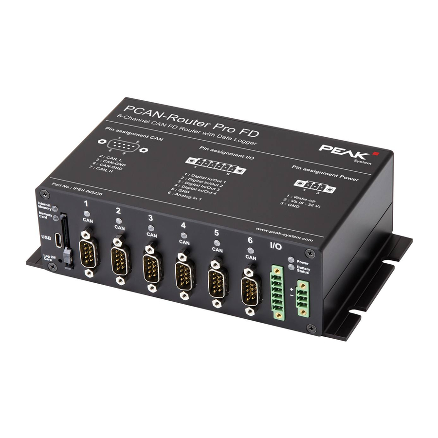
- Page 1 PCAN-Router Pro FD 6-Channel CAN FD Router with I/O and Data Logger User Manual Document version 1.4.0 (2020-08-14)
- Page 2 Part Number PCAN-Router Pro FD IPEH-002220 PCAN is a registered trademark of PEAK-System Technik GmbH. BroadR-Reach® is a trademark of Broadcom Corporation. CANopen® and CiA® are registered trademarks of CAN in Automation e.V. All other product names in this document may be the trademarks or registered trade- marks of their respective companies.
-
Page 3: Table Of Contents
PCAN-Router Pro FD – User Manual Contents Introduction Properties at a Glance Operation Requirements Scope of Supply Connectors and Operating Elements Power Supply CAN over D-Sub Connectors Inputs and Outputs (I/O) Status LEDs USB Connection SD Card Slot and Internal Memory... - Page 4 PCAN-Router Pro FD – User Manual Firmware Transfer Configurable Data Logging Installation Configuration 7.2.1 Nominal and Data Bit Rates 7.2.2 CAN Specification and Options 7.2.3 Trace Options 7.2.4 Maximum File Size 7.2.5 Trace Mode 7.2.6 Memory Card 7.2.7 Handling of the USB Connection 7.2.8...
-
Page 5: Introduction
PCAN-Router Pro FD – User Manual Introduction With six channels, the PCAN-Router Pro FD links the data traffic of modern CAN FD and classic CAN buses. Pluggable CAN transceiver modules allow flexible adaptation of each CAN channel to the respective requirements. In addition, the router is equipped with an analog input and four digital I/Os. - Page 6 PCAN-Router Pro FD – User Manual Alternative pluggable transceiver modules on request (details on page 14) CAN connections are D-Sub, 9-pin CAN termination switchable, separately for each CAN channel Wake-up function using separate input, CAN bus, or real-time clock...
-
Page 7: Operation Requirements
D-Sub connector Extended operating temperature range from -40 to 85 °C (-40 to 185 °F) Operation Requirements The transfer of the firmware via CAN requires a PEAK CAN interface Scope of Supply PCAN-Router Pro FD in aluminum casing including mating... -
Page 8: Connectors And Operating Elements
This chapter describes the connections on the front panel of the PCAN-Router Pro FD. Figure 1: Pin assignment on the front panel of the PCAN-Router Pro FD Figure 2: Description of the pin assignments on the top of the housing... -
Page 9: Power Supply
PCAN-Router Pro FD – User Manual Power Supply For the operation of the PCAN-Router Pro FD a voltage source with nominal 12 V DC is required, 8 to 32 V are possible. The input is electronically protected with reverse polarity and overvoltage protection. -
Page 10: Can Over D-Sub Connectors
PCAN-Router Pro FD – User Manual CAN over D-Sub Connectors A high-speed CAN bus (ISO 11898-2) is connected to the 9-pin D Sub connector. The CAN assignment corresponds to the CiA® 303-1 specification. Figure 4: Pin assignment High-speed CAN Inputs and Outputs (I/O) The I/O connector has 4 digital inputs and outputs and one analog input. -
Page 11: Status Leds
Note: Access to the USB connection via the CPU is not possible. SD Card Slot and Internal Memory The PCAN-Router Pro FD is equipped with an internal memory card. Optionally, an additional SD card can be inserted into the SD card slot. -
Page 12: Log Off Card Button
PCAN-Router Pro FD – User Manual The internal memory and the external memory card of the PCAN- Router Pro FD can be accessed via a USB connection with a PC. Log Off Card Button The function of the Log Off Card button can be programmed with a... -
Page 13: Operation
PCAN-Router Pro FD – User Manual Operation Ensuring Power Supply The PCAN-Router Pro FD must be supplied as standard with a nominal 12 V (8 to 32 V possible) DC voltage via the power connection. Note: If you install a backup battery (see section 4.4) and it is charged, the device can also be operated without a power supply (e.g. -
Page 14: Hardware Modifications
PCAN-Router Pro FD – User Manual Hardware Modifications You can make various hardware adjustments on the board of the PCAN-Router Pro FD: Using an alternative CAN Transceiver module (section 4.1) Adapting the termination for a CAN bus (section 4.2) Changing the button cell for the real-time clock (section 4.3) - Page 15 PCAN-Router Pro FD – User Manual Figure 6: Positions of the transceiver modules for the six CAN FD channels Attention! Electrostatic discharge (ESD) can damage or destroy components on the card. Take precautions to avoid ESD. Do the following to change a transceiver module: Disconnect the device from the power supply.
-
Page 16: Setting The Termination For A Can Bus
13. Fasten the four screws to the front and rear of the housing. When the PCAN-Router Pro FD is restarted, it automatically detects the type of CAN transceiver module used and sets the transmission standard (see table above) for the CAN channel accordingly. - Page 17 PCAN-Router Pro FD – User Manual Figure 7: Positions of the switch blocks for CAN termination on the front board Type of Transceiver Termination at Switch Position High-speed-CAN (ISO 11898-2) none 120 between Transceiver installed by default. CAN_L and CAN_H Low-speed-CAN (ISO 11898-3) 4.7 k...
-
Page 18: Changing The Button Cell For The Real-Time Clock (Rtc)
Changing the Button Cell for the Real- Time Clock (RTC) The real-time clock (RTC) installed in the PCAN-Router Pro FD is supplied by a button cell of the IEC type CR1620 (3 V) as long as the device is switched off (without power supply). -
Page 19: Installing Backup Battery
Fasten the four screws to the front and back of the housing. Installing Backup Battery On the board of the PCAN-Router Pro FD a backup battery in the form factor 18650 can be inserted, which must be protected against short circuit, overcharging, and deep discharge (Protection PCB). - Page 20 PCAN-Router Pro FD – User Manual Figure 9: Position of the backup battery on the board Attention! Electrostatic discharge (ESD) can damage or destroy components on the card. Take precautions to avoid ESD. Do the following to install the backup battery: Disconnect the device from the power supply.
- Page 21 PCAN-Router Pro FD – User Manual Push the board back into the first rail of the housing. Replace the housing cover and the back panel. 10. Only with optional BroadR-Reach® interface: Fasten the two screws of the D-Sub connector to the rear of the housing.
-
Page 22: Creating Own Firmware
PCAN-Router Pro FD – User Manual Creating Own Firmware With the help of the development package, you can program your own application-specific firmware for PEAK-System programmable hardware products. Download of the development package: URL: www.peak-system.com/quick/DLP-DevPack System Requirements: ® PC with Windows... - Page 23 PCAN-Router Pro FD – User Manual Do the following to create your own firmware: Create a folder on your local PC. We recommend using a local drive. Copy the complete unzipped PEAK-DevPack directories into your folder, incl. all subs. No installation is required at all.
-
Page 24: Firmware Upload
The firmware upload is done via a CAN bus with the supplied Windows program PEAK-Flash. System Requirements In order to upload a new firmware to the PCAN-Router Pro FD, the following requirements must be met: CAN interface of the PCAN series for the computer (e.g. -
Page 25: Firmware Transfer
The selected CAN channel must be connected alone to the PC. Firmware Transfer Do the following to transfer a new firmware with PEAK-Flash The software PEAK-Flash is included in the development package, which can be downloaded via the following link: www.peak-system.com/quick/DLP-DevPack... - Page 26 PCAN-Router Pro FD – User Manual Figure 12: Main window of PEAK-Flash Click the Next button. Click on the Modules connected to the CAN bus radio button. In the Channels of connected CAN hardware drop-down menu, select a CAN interface connected to the computer (e.g.
- Page 27 PCAN-Router Pro FD – User Manual Figure 13: Hardware selection Click on Detect. In the list, the PCAN-Router Pro FD appears together with the Module ID and Firmware version. If not, check whether a proper connection to the CAN bus with the appropriate nominal bit rate exists.
- Page 28 14. After the process is complete, click Next. 15. You can exit the program. 16. Turn the rotary switch on the PCAN-Router Pro FD back to the previously set module ID. 17. Restart the device by interrupting the power supply for the change of the rotary switch to take effect.
-
Page 29: Configurable Data Logging
PCAN-Router Pro FD – User Manual Configurable Data Logging In addition to the programming examples, the PCAN-Router Pro FD is delivered with a ready-to-use firmware for tracing CAN data. The CAN messages can be recorded on the internal eMMC memory or on an inserted SD card which are both accessible via the USB connector. -
Page 30: Installation
Defining beep patterns for tracing start, end, and error events Defining the LED blinking pattern Note: When using the firmware for data logging, the other programmable features of the PCAN-Router Pro FD are not available. Installation Important note for devices with a serial number up to 150: The development package contains various upgrades in the directory \Hardware\PCAN-Router Pro FD\Upgrades\. -
Page 31: Configuration
PCAN-Router Pro FD – User Manual Configuration The firmware comes with a file named config.txt which can be found in the same directory as the firmware. All settings of the CAN channels and logging features are configured with this file. -
Page 32: Nominal And Data Bit Rates
PCAN-Router Pro FD – User Manual Note: If config.txt files were uploaded to both memory cards, configuration of the internal eMMC memory card is used. 7.2.1 Nominal and Data Bit Rates In this section, the nominal and data bit rates for all 6 CAN channels are configured separately by setting the register values. -
Page 33: Can Specification And Options
Listen-Only mode can be added as an option. pflash7E7 This option enables a firmware update via PEAK-Flash without turning the rotary switch on the rear of the housing to F. In this case the new firmware is transferred to the... -
Page 34: Trace Options
If tracing is stopped and restarted, the data is stored in the same file. TRC_FILE_MAX_SZ_MB=256 Tip: Using the software PEAK-Converter, trace files can be converted into other formats and single channels can be extracted. The PEAK-Converter can be downloaded for free... -
Page 35: Trace Mode
PCAN-Router Pro FD – User Manual 7.2.5 Trace Mode In this section, the trace mode is configured. This covers handling of existing files when a new recording is started and the behavior if the memory's maximum capacity is reached. TRC_MODE=2... -
Page 36: Handling Of The Usb Connection
PCAN-Router Pro FD – User Manual Option Description EMMC The internal eMMC memory card is used for tracing. This value is the default setting. 7.2.7 Handling of the USB Connection This setting specifies how an existing USB connection is handled when tracing is started. -
Page 37: Timeouts
PCAN-Router Pro FD – User Manual 7.2.9 Timeouts With these settings timeouts are specified in milliseconds. No CAN traffic TRC_STOP_TRAFFIC_TO specifies a timeout for no CAN traffic. If no CAN message was received for this duration, tracing is stopped. TRC_STOP_TRAFFIC_TO=0 Terminal 15 Loss TRC_STOP_T15_TO specifies a timeout for terminal 15 loss. -
Page 38: Beep Patterns
PCAN-Router Pro FD – User Manual 7.2.10 Beep Patterns With these settings beep patterns for the events trace start, stop, and error are specified. The general structure of a beep pattern configuration is as follows: KEYWORD=Repetition Tick-Duration Pattern Parameter Description... -
Page 39: Led Blinking Patterns
PCAN-Router Pro FD – User Manual 7.2.11 LED Blinking Patterns The memory card LEDs are blinking if tracing is started and the cards are accessed. The CAN LEDs are blinking if CAN traffic occurs. With the following setting the blinking pattern can be configured. -
Page 40: Operation
PCAN-Router Pro FD – User Manual Note: The indicated CAN ID must not be used on any connected CAN bus. By default, this feature is commented out to prevent unintended behavior. Operation 7.3.1 LEDs Figure 15: Status, CAN channel, and memory card LEDs on the front panel... -
Page 41: Control With The Log Off Card Button
PCAN-Router Pro FD – User Manual CAN Channel LEDs Status Description Orange blinking Tracing is Tracing is enabled for this channel. The enabled LED is blinking due CAN traffic. The blinking pattern of the memory card and CAN channel LEDs can be configured (see chapter 7.2.11 page 39). - Page 42 PCAN-Router Pro FD – User Manual Tip: Using the software PEAK-Converter, trace files can be converted into other formats and single channels can be extracted. The PEAK-Converter can be downloaded for free from our website www.peak-system.com. Memory Card Capacity and Logging Duration...
-
Page 43: Technical Specifications
PCAN-Router Pro FD – User Manual Technical Specifications Connectors 6 x D-Sub (m), 9 pins Assignment according to specification CiA® 303-1 USB port type C Superspeed USB 3.0 Upstream Inputs/outputs Phoenix mating connector MC1.5/2-STF-3.81, 6-pin; 2 x digital input or output with high-side switch... - Page 44 PCAN-Router Pro FD – User Manual Analog Inputs Count Connectors Analog In 1 Resolution A/D converter 12 bit Input voltage maximum + 32 V Input impedance 222 kΩ Measuring range 0 – 33.3 V Measurement resolution 8 mV (per LSB) Measurement accuracy ±...
- Page 45 PCAN-Router Pro FD – User Manual Digital Outputs High-side Low-side Maximum output current 0.7 A minimal 1.2 A minimal (current limitation) 1.5 A typically 1.8 A typically 2.4 A maximum 3 A maximum Protection Overcurrent (0.7 - 2.4 A) Overcurrent (1.2 - 3 A)
- Page 46 PCAN-Router Pro FD – User Manual Data Logging Initialization duration of the 50 ms (wake-up duration not included) data logger firmware Recording format Proprietary binary format (*.btrc), Conversion options with the supplied Windows program: - PCAN-Trace (*.trc) - Vector trace (*.asc) - comma separated values (*.csv)
-
Page 47: Appendix A Optional Interfaces
PCAN-Router Pro FD – User Manual Appendix A Optional Interfaces On request, the PCAN-Router Pro FD can be equipped with an Ethernet interface via an RJ-45 socket or with a BroadR-Reach® interface via a D-Sub connector. Ethernet interface via RJ-45 Socket... - Page 48 PCAN-Router Pro FD – User Manual BroadR-Reach® Interface via D-Sub Connector Figure 17: BroadR-Reach® interface via D-Sub connector on the back of the housing (only on request) Pin Signal TRX+ TRX-...
-
Page 49: Appendix Bce Certificate
PCAN-Router Pro FD – User Manual Appendix B CE Certificate... -
Page 50: Appendix C Dimension Drawing
PCAN-Router Pro FD – User Manual Appendix C Dimension Drawing Figure 18: Dimension drawing PCAN-Router Pro FD The figures do not correspond to the original size. -
Page 51: Appendix D Disposal Information (Battery)
The device and the battery it contains must not be disposed of with household waste. Remove the battery from the device for proper separate disposal. The PCAN-Router Pro FD contains the following battery: 1 x button cell CR1620 3.0 V Important Note: If you have installed a backup battery (form...
Need help?
Do you have a question about the PCAN-Router Pro FD and is the answer not in the manual?
Questions and answers