Table of Contents
Advertisement
Quick Links
TC8000
to 28 CHANNEL AUDIO/INTERCOM
AND DATA
FIBER OPTIC MULTIPLEXER
User's Manual
MODEL:
S/N:
DATE:
Although every effort has been made to insure that this manual is
urrent and a urate as of date of publi ation, no guarantee is given or
implied that this do ument is error free or a urate with regard to any
spe ifi ation. TC Communi ations, In . reserves the right to hange or
modify the ontents of this manual at any time without prior notifi a-
tion.
©
OPYRIGHT 1992-2020. ALL RIGHTS RESERVED.
TC Communications, Inc. 17881 Cartwright Road - Irvine, CA 92614
Tel: (949) 852-1972 Fax: (949) 852-1948
Notice!
Web Site: www.tccomm.com
Email: info@tccomm.com
NL-80000-01-70
Advertisement
Table of Contents

Subscribe to Our Youtube Channel
Related Manuals for TC Communications TC8000


Summary of Contents for TC Communications TC8000
- Page 1 © OPYRIGHT 1992-2020. ALL RIGHTS RESERVED. TC Communications, Inc. 17881 Cartwright Road - Irvine, CA 92614 Tel: (949) 852-1972 Fax: (949) 852-1948 Web Site: www.tccomm.com Email: info@tccomm.com...
-
Page 2: Table Of Contents
TC8000 4 to 8CH Audio/Intercom ser's Manual Table Of Contents Rev. 7.0 Chapter 1 - Overview ......................3 Features ............................3 Description ............................3 TC8000 Functional Block Diagram .................... Fiber Optics ............................. 5 Connectors ..........................5 Launch Power, Sensitivity and Loss Budget ................5 Transmission Distances (typical) .................... -
Page 3: Chapter 1 - Overview
Sin e the analog and voi e signals are digitized, the voi e quality will not degrade as the distan e is extended. For example, distan es to 30 km are typi al for a pair of TC8000's with 1300nm single mode fiber front end. -
Page 4: Tc8000 Functional Block Diagram
TC8000 4 to 8CH Audio/Intercom ser's Manual Rev. 7.0 TC8000 Functional Block Diagram Convert parallel data to serial Typi al opti al laun h power: -19dBm (850/1300nm MM) -14dBm (1300nm SM) to opti able Convert serial data to parallel Typi al opti al re eiving sensitivity:... -
Page 5: Fiber Optics
Transmission Distances (typical) The TC8000 will work with all popular sizes and types of fiber. Transmission distan es up to 4km* are typi al over multimode fiber at 850nm and 6km* at 1300nm. Distan es to 35km* are typi al over sing le mode fiber at 1300nm. -
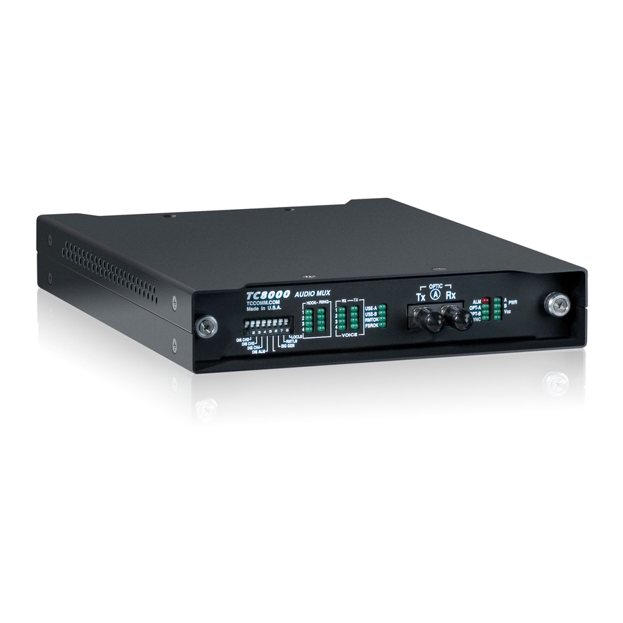
Page 6: Front And Rear Panel Views
TC8000 4 to 8CH Audio/Intercom ser's Manual Rev. 7.0 AUD IO M UX Base Card AUDIO MUX Expansion Card Figure 3. TC8000 Front Panel View Base card Channe ls 1-4 Dry Contact Relay Connector A nalog/I ntercom Card Expan sion Card... -
Page 7: Base Card's Leds And Dip Switches
TC8000 4 to 8CH Audio/Intercom ser's Manual Base Card LEDs, DIP Switches Rev. 7.0 AUDIO M UX Figure 5. TC8000 Base Card's Front Panel NL-80000-01-70 - 7 -... -
Page 8: Expansion Card's Leds And Dip Switches
TC8000 4 to 8CH Audio/Intercom ser's Manual Rev. 7.0 Expansion Card LEDs, DIP Switches AUDIO MUX Figure 6. TC8000 Analog Expansion's Card Front Panel NL-80000-01-70 - 8 -... -
Page 9: Electrical Signal Interface Connection & Virtual Pin Assignment
Manual Electrical Signal Interface Connection & Pin Assignments Rev. 7.0 The RJ-11 onne tors are lo ated at the rear panel of the TC8000. Analog & Intercom Pin Assignments RJ-11 x 8 gang onne tor at the rear panel. -
Page 10: Rs-232 Async With Control And Sync
(RxD-). Either pin 6 or pin 1 an be Signal Ground. Only RS-422/RS-485 Asyn ommuni ations an be used with the TC8000 due to the limited number of pins on the RJ-11 onne tor. Figure 11. RS- 22/RS- 85 Async Pin Assignments & Virtual Connection Diagrams... -
Page 11: Two Wire (Half Duplex) Asynchronous
TC8000 4 to 8CH Audio/Intercom ser's Manual Rev. 7.0 RS- 85 (2 wire) Electrical Signal Interface Connection & Pin Assignments Two wire (Half Duplex) RS- 85 Asynchronous (Optional) For two wire RS-485, use pins 3 and 4. Either pin 6 or pin 1 an be Signal Ground. -
Page 12: Ttl Asynchronous
The re eiver side has a dry- onta t losure relay swit h. The " lose" and "open" status is ontrolled by a relay swit h inside the TC8000. It refle ts the remote dete tor's "on" and "off" status. -
Page 13: Rj-11 To Db25 Female (Async & Sync) Connection Cables
TC8000 4 to 8CH Audio/Intercom ser's Manual Rev. 7.0 RJ-11 to DB25 Female (Async & Sync) Connection Cables The user's devi e an be a DCE or DTE devi e (whi h may have a DB25 male onne tor). The following eight illustrations depi t the RS-232/TTL, RS-232 Asyn with ontrol, RS-232 Syn &... - Page 14 TC8000 4 to 8CH Audio/Intercom ser's Manual Rev. 7.0 Figure 19. RJ-11 (SYNC DCE) RS-232 Pin Assignments & Connection Figure 20. RJ-11 (SYNC DTE) RS-232 Pin Assignments & Connection Figure 21. RJ-11 (ASYNC DCE) RS- 22/RS- 85 Pin Assignments & Connection Figure 22.
-
Page 15: Chapter 2 - Installation
The terminal blo k onne tor for power an be plugged into any power ja k (either A or B) on the rear panel. Please refer to the rear panel page (page 6) for lo ations. Sin e ea h TC8000 is equipped with power redundan y apability, the power LEDs on the front panel will be "ON"... -
Page 16: System Start Up
5VDC derived from either power A or B Apply a valid opti signal either from a remote peer TC8000 or loop ba k from its own opti Tx. Following LED hanges should be observed: Alarm LED is turned off. -
Page 17: Chapter 3 - Troubleshooting
TC8000 4 to 8CH Audio/Intercom ser's Manual Chapter 3 - Troubleshooting Rev. 7.0 General The fiber opti link and/or the onne tors are frequently the sour e of various problems. Che k out the onne tors and the integrity of the link first. Ideally, the link should be alibrated for total loss after the installation has been ompleted. -
Page 18: Chapter - Specifications
TC8000 4 to 8CH Audio/Intercom ser's Manual Chapter - Specifications Rev. 7.0 Data Rates Async and Sync(per channel) ..............DC up to 19.2Kbps Audio Bandwidth Analog, Intercom ..................... 300 to 3.4 KHz Channel Capacity Channels ......................... 4 to 28 Optical Transmitter .................... -
Page 19: Physical
TC8000 4 to 8CH Audio/Intercom ser's Manual Rev. 7.0 Physical rack mountable card: Height ........................(19cm) 7.00" Width ........................(3.2cm) 1.25" Depth ......................... (22.8cm) 9.00" Weight ....................... (280gm) 10 oz standalone box: Height ........................(19cm) 7.2" Width ........................(3.2cm) 2.6"... -
Page 20: Chapter 5 - 19" Rack & Power Card
TC8000 4 to 8CH Audio/Intercom ser's Manual Rev. 7.0 Chapter 5 - 19" Rack & Power Card Features U height (7") Dual Power Capability (Automatic Switchover in the Event of Failure) Universal Switching Power Supply Accepts 90 to 263 VAC and 7 to 63 Hz AC Optional - 8VDC Power Supply Available... -
Page 21: Chapter 6 - Appendix
TC8000 4 to 8CH Audio/Intercom ser's Manual Chapter 6 - Appendix Rev. 7.0 Return Policy To return a produ t, you must first obtain a Return Material Authorization number from the Customer Servi e Department. If the produ t’s warranty has expired, you will need to provide a pur hase order to authorize the repair. - Page 22 TC8000 4 to 8CH Audio/Intercom ser's Manual Rev. 7.0 Limitation of Liability (Cont.) In no event shall liability atta hed to TC Communi ations, In . unless noti e in writing is given to TC Communi ations, In . within ten days of the o urren e of the event giving rise to su h laim.
Need help?
Do you have a question about the TC8000 and is the answer not in the manual?
Questions and answers