Table of Contents
Advertisement
Quick Links
Advertisement
Table of Contents

Subscribe to Our Youtube Channel
Related Manuals for TC Communications TC8612


Summary of Contents for TC Communications TC8612
- Page 1 TC8612 8 Channel DIO Over T1/E1 Multiplexer User Manual MNL-86120-01-01...
- Page 2 Other product and brand names may be trademarks or registered trademarks of their respective owners. Documentation Disclaimer This document is provided “as-is” and is to be used only as a general guide. TC Communications disclaims all warranties, express or implied, regarding the accuracy of the information. TC Communications shall not be liable for any indirect, special, incidental, or consequential damages (including damages for loss of business, loss of profits, loss of business information, business interruption or other pecuniary loss) arising out of errors in this document.
- Page 3 These alert symbols are used in Caution, Warning, and Danger notes. Symbol Meaning Pinching or crushing hazard Electrical hazard. Equipment alert: be careful of damage from static electricity General alert: used for all other hazardous conditions (referring to people, not equipment). TC8612 Rev 1.1 User Manual...
-
Page 4: Table Of Contents
CSU Loop Operation ........B-2 TOC-1 TC8612 Rev 1.1 User Manual... - Page 5 Limitation of Liability ........C-2 TC8612 Rev 1.1...
-
Page 6: General Information
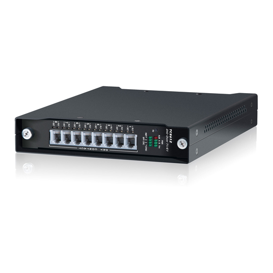
A built-in sync mechanism verifies both device and T1/E1 link operation. No other test equipment is required for link and device verification. The TC8612 is compatible with standard 100Ω T1 for copper line lengths up to 6000ft and up to 2.5km for 75Ω / 120Ω E1 (copper line length is the distance between the TC8612 and the T1/E1 cross-connect). - Page 7 Chapter 1 Introduction Product Description Figure 1-1 TC8612 DIO Over T1/E1 Multiplexer TC8612 Rev 1.1 User Manual...
-
Page 8: Features
• T1 Features: ESF Framing Support (SF Framing, Optional) Supports Line Length up to 3000ft (T1)* 24 timeslots (DS0) 1-24. TC8612 utilizes timeslots 12 and 24 • E1 Features: Supports Line Length up to 2.5km PCM31C Framing Support (PCM30, PCM30C, PCM31 Optional) 32 timeslots 0-31. -
Page 9: Applications
*Note: For line lengths beyond 655ft additional testing is required. 1.2.2 Applications The TC8612 Serial-over-T1/E1 Multiplexer provides an inexpensive method for connecting Async/Sync terminals, printers, and status collecting devices. It is also used in harsh environments where EMI/RFI interference, ground loops and lightning conditions may exist. -
Page 10: Specifications
PWR A, PWR B, Vcc, ALM, SYNC, AMI, BPV, LOS, AIS, RAI, CRC, RMT DET (1 each Dry Contact Ports 1-8) RLY (1 each Dry Contact Ports 1-8) Diagnostic Functions Local Loopback, Remote Loopback, and T1/E1 Loopback TC8612 Rev 1.1 User Manual... - Page 11 Depth (24.89 cm) 9.80" Weight (907g) 2.0 lbs. Physical (Rack mount 1U “Pizza Box” with two cards) Height Height (4.45 cm) 1.75" Width (48.26 cm) 19" Depth (22.86 cm) 9" Weight (1.86 Kg) 4.1 lbs. TC8612 Rev 1.1 User Manual...
-
Page 12: General Information
Customer Service Department at TC Communications, Inc. at (949) 852-1973. Equipment Location The TC8612 should be located in an area that provides adequate light, work space and ventilation. Important Avoid locating it next to any equipment that may produce electrical interference or strong magnetic fields, such as elevator shafts or heavy duty power supplies. -
Page 13: Power Supply
The Power "A" and/or "B" and VCC LEDs should be lit. TC8612 cards installed in the 1U rack chassis will not show the NOTE PWR A LED in the “On” lit state and will be Off. This is normal and the power to the card will be monitored by the VCC LED being “On”... -
Page 14: System Configuration
System Configuration The TC8612 has been pre-tested and switches have been set per factory specifications. The channels can be factory configured (in groups of four) for RS- 232, RS-422 and RS-485 interfaces at the time of ordering. -
Page 15: Rear Panel
Figure 2-2 TC8612 Rear Panel 2.7.2.1 Rear Panel DIP Switch Functions The DIP switch functions on the TC8612 are described below. To activate the function, slide the appropriate switch to the On (Down) position. • LOCLB: Local Loopback. This switch (SW1) initiates the Local Loopback function. - Page 16 E1 application. For example, in a T1/E1 application, this is the length of twisted pair cable connecting the TC8612 to the user's equipment, which may be a CSU or DSU. See Table 2-1 and Table 2-2. Table 2-1: Copper Line Length Setup Table...
-
Page 17: Electrical Signal Interface Connection & Pin Assignments
2.7.3.1 Dry Contact Ports For dry contact closure applications, the TC8612 can be used as either the Closure Detector or Relay depending on which pins are used. By default, the dry contact Relay will open when T1/E1 link is not in sync. - Page 18 Chapter 2 Installation System Configuration Figure 2-3 Dry Contact Closure Detector TC8612 Rev 1.1 User Manual...
-
Page 19: Quick Start Guide 3.1 Introduction
Quick Start Guide Introduction The TC8612 is designed for quick and easy installation. First, configure the unit for your specific application by setting the Line Code, and Line Length DIP switches. Once configured, you can connect the Dry Contact, T1/E1 signal source and power. -
Page 20: Latched Alarm
It is highly recommended to conduct bench tests before actual installation. Bench testing allows the user to become familiar with all the functions and features of the TC8612 in a controlled environment. Knowledge of these functions and features will ease installation and troubleshooting efforts later on. -
Page 21: Remote Unit Status Monitoring And Remote Unit Alarm Reset
Remote Unit Status Monitoring and Remote Unit Alarm Reset Remote Unit Status Monitoring and Remote Unit Alarm Reset TC8612 is capable of monitoring the remote unit status and resetting the remote unit alarm condition. Short press (less than 3 seconds) the "R2" button will toggle between local and remote status display. -
Page 22: Local Loopback Test
1 & 2 of Port 1 will be looped back to pin 1 & 2 of Port 3. The loopback is formed inside the TC8612 after the input signal is converted to the TTL level. The purpose of this test is to verify the input and output wiring connections, signal input receiver and signal output driver. -
Page 23: Remote Loopback Test
Remote Loopback Test When you have completed the Local Loopback test for both units, proceed to the next step. Connect the local and remote TC8612 units as shown on the diagram below. Connect the T1/E1 connections as shown on the diagram below. Be sure to make the correct pin connections, refer to page 2-6 for pin assignments. -
Page 24: T1/E1 Local Loopback Test
The “LOS” LED should be off indicating that a valid T1/E1 signal is being received. If the “LOS” LED is flashing it means that the TC8612 is not receiving a valid T1/E1 or the T1/E1 cable is in question. -
Page 25: General
General Alarm conditions occur whenever a power or sync "fault" condition is detected by the TC8612. Under normal operation, PWR, Vcc, and SYNC LEDs should be lit. All LEDs are OFF If no LEDs are lit on the unit, check the DC power supply, connector plug, and/or the power source. -
Page 26: Appendix A 19" Rack Mount Card Cage
This chassis ground connection point is available in case chassis ground is taken into design consideration by the end user. 17.3” (43.94 cm) TCRM195 1.75” (4.45 cm) 19” (48.26 cm) 9” (22.86 cm) TC8612 Rev 1.1 User Manual... -
Page 27: Appendix B R2 Button & Led Functions
R2 Button & LED Functions R2 (“Reset Too”) Button Description The recent enhancements implemented on the TC8612 (DIO over T1/E1) will make troubleshooting a much easier process. The alarm LEDs - BPV, CRC, and SYNC - can now latch abnormal conditions until they are reset by the user. These functions are realized in part by the newly added "R2"... -
Page 28: Led Functions
ISP may perform BER testing and other tests on the looped link. To cancel the loop, the ISP must transmit the CSU Loop Down Code towards the unit. Alternatively, disconnecting the T1/E1 cable will also cancel the loop. TC8612 Rev 1.1 User Manual... - Page 29 Buyer, or may give written authorization to Buyer to return the goods to TC Communications, Inc., transportation charges prepaid, for examination by TC Communications, Inc. Buyer shall bear the risk of loss until all goods authorized to be returned are delivered to TC Communications, Inc. TC Communications, Inc.
- Page 30 The shipping expense to TC Communications should be prepaid. The product should be properly packaged and insured. After the product is repaired, TC Communications will ship the product back to the shipper at TC's cost to U.S. domestic destinations. (Foreign customers are responsible for all shipping costs, duties and taxes [both ways].
Need help?
Do you have a question about the TC8612 and is the answer not in the manual?
Questions and answers