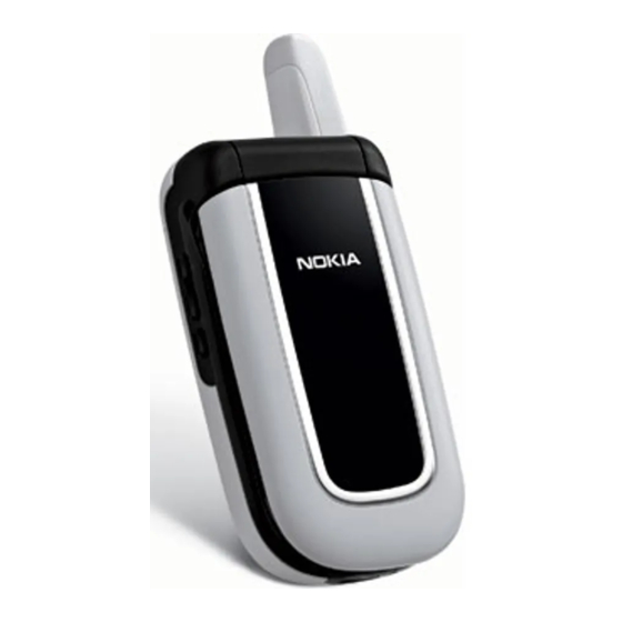
Nokia 2255 Disassembly/Assembly
Mobile terminal
Hide thumbs
Also See for 2255:
- User manual (54 pages) ,
- Manual (50 pages) ,
- Baseband description and troubleshooting (44 pages)

Related Manuals for Nokia 2255


Summary of Contents for Nokia 2255
- Page 1 Nokia Customer Care 2255 (RM-97) Mobile Terminal Disassembly/Assembly ©2005 Nokia Corporation Issue 1 10/2005 Company Confidential...
-
Page 2: Table Of Contents
2255 (RM-97) Disassembly/Assembly Contents Page Safety Information ............................3 ESD Protection ............................. 3 Assembly Instructions ........................... 4 Disassembly Instructions ..........................4 1. Remove the Battery Cover ........................4 2. Remove the Antenna ..........................4 3. Remove the D-cover Screws ........................ 5 4. -
Page 3: Safety Information
• Every repair action involving opening the phone or handling the phone components must be done under ESD protection. • ESD-protected spare part packages MUST NOT be opened/closed outside an EPA. For more detailed information about ESD protection and EPAs, contact your local Nokia Customer Care representative. ©2005 Nokia Corporation... -
Page 4: Assembly Instructions
2255 (RM-97) Disassembly/Assembly Assembly Instructions To assemble the mobile terminal, follow the "Disassembly Instructions" in reverse order. Disassembly Instructions Use the following steps to disassemble the mobile terminal. 1. Remove the Battery Cover a. Turn the mobile terminal off. b. Apply pressure to the battery cover, pushing towards the bottom of the mobile terminal to remove it. -
Page 5: Remove The D-Cover Screws
2255 (RM-97) Nokia Customer Care Disassembly/Assembly 3. Remove the D-cover Screws Using a Torx 6 Plus screwdriver, undo the three screws beginning with the center top, followed by the two bottom screws. Use torque driver set to 13 Ncm (+/-2 Ncm) @ 550 RPM. -
Page 6: Remove Flex Connector
2255 (RM-97) Disassembly/Assembly b. Remove the D-cover by lifting upward and then sliding off of the B/C-cover assembly, as shown below. 5. Remove the Flex Connector Using the SRT-6 tool, unsnap the main flex connector, then release the snaps on either side of the PWB. -
Page 7: Remove The Pwb
2255 (RM-97) Nokia Customer Care Disassembly/Assembly 6. Remove the PWB Gently lift and rotate the PWB from the assembly, so that the side key flex cable is removed along with the PWB. Side key flex cable 7. Remove the Side Key Flex Cable Using the SRT-6 opening tool, remove the side key flex cable from the PWB by opening the connection. -
Page 8: Remove The Hinge
2255 (RM-97) Disassembly/Assembly 9. Remove the Hinge Grasp the hinge assembly with both hands as shown and pull the hinge away from the A/B-cover assembly to unsnap the hinge pin. Caution: Do not separate the two assemblies after the hinge is opened. -
Page 9: Disassemble The A/B-Cover
2255 (RM-97) Nokia Customer Care Disassembly/Assembly 10. Disassemble the A/B-cover a. Using a SRT-6 tool, unsnap the A/B-cover assembly beginning at the slots on either side of the hinge. b. Continue prying around the assembly to separate the covers. Unsnap here 11. - Page 10 2255 (RM-97) Disassembly/Assembly b. Gently pry up on the display shield with the SRT-6 tool and rotate upwards to reveal the LCD connector. c. Using the SRT-6 tool unsnap LCD connector and separate the LCD display assembly from the display shield assembly.
-
Page 11: Remove The Main Flex Cable
2255 (RM-97) Nokia Customer Care Disassembly/Assembly 12. Remove the Main Flex Cable a. Note of the location of the flex access slot. Gently slide the LCD assembly so that the flex slides through the access slot within the hinge. Separate the two assemblies. -
Page 12: Remove The Lcd Display
2255 (RM-97) Disassembly/Assembly 14. Remove the LCD Display a. Open the LCD flex connection on LCD assembly using the SRT-6 tool. b. Lift the display to remove it. Caution: Do not damage the LCD flex cable while separating the components. -
Page 13: Remove The Super Grommet
2255 (RM-97) Nokia Customer Care Disassembly/Assembly 16. Remove the Super Grommet Using tweezers, grasp the super grommet to lift and remove it from the D-cover. 17. Remove the DC Jack Use either tweezers or DC plug to lift the DC Jack upwards from its position to remove it. -
Page 14: Remove The Microphone
2255 (RM-97) Disassembly/Assembly 18. Remove the Microphone Using tweezers, pluck the microphone from its position. Note for Assembly: Once removed, always replace the microphone module with a new assembly. ©2005 Nokia Corporation Page 14 Company Confidential Issue 1 10/2005...
Need help?
Do you have a question about the 2255 and is the answer not in the manual?
Questions and answers