Table of Contents
Advertisement
Quick Links
Advertisement
Table of Contents

Summary of Contents for Raptor Photonics Ninox 1280
- Page 1 NINOX 1280 Model: NX1.7-VS-CL-1280 USER MANUAL...
-
Page 2: Table Of Contents
CONTENTS INTRODUCTION ................................... 3 Scope ..................................3 CAMERA CARE ..................................3 Cleaning the Sensor Window ............................ 3 SPECIFICATION ..................................4 Camera Specification..............................4 Specification Table ..............................4 MECHANICAL DESIGN ................................. 5 Mechanical Model ..............................5 Physical Interface ..............................6 Mounting to Microscope ............................. 6 Mounting to a tripod or optical table ......................... -
Page 3: Introduction
INTRODUCTION Scope This manual covers the Ninox 1280 digital camera and all applicable components. Raptor recommends that this manual be used to optimize camera operation. CAMERA CARE Cleaning the Sensor Window Raptor cameras require no regular maintenance except occasional external cleaning of the sensor window (the glass window between the camera sensor and the microscope or lens). -
Page 4: Specification
SPECIFICATION Camera Specification The Ninox 1280 VIS-SWIR is designed for high resolution applications requiring visible to SWIR imaging (400-1700nm). The camera uses an InGaAS sensor with a resolution of 1280 x 1024. High-speed low- noise electronics provide linear response and sensitivity for rapid image capture. -
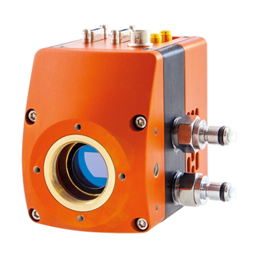
Page 5: Mechanical Design
Note 1: Optional filters available: Low, High or bandpass. Note 2: For exposure times up to 10s, the camera will have to be switched to long exposure mode. This mode only operates in low gain and there is no NUC. When in normal mode and in low gain, the maximum exposure time is 90ms with an active NUC. -
Page 6: Physical Interface
(x2 IN/OUT) Mounting to Microscope The Ninox 1280 has a standard C-Mount that should easily screw onto any microscope port. Mounting to a tripod or optical table The camera has a ¼-20 BSW (Whitworth), threaded hole to mount to a tripod or an optical table. -
Page 7: Xcap Compatibility
(if applicable). Below is an image of a normal setup of the camera, computer and chiller. For most applications, the chiller may not be necessary to use with the Ninox 1280, as the fan is normally adequate at dissipating heat from the device. If imaging the camera in a high ambient temperature environment, water cooling may be required to keep the PCB temperature low enough in order to hit the optimum -15 ̊... -
Page 8: Connecting Camera To Chiller
• Click “Start” to begin circulating water. • Now set the Temperature set point on the circulator. For the Ninox 1280 camera, 20°C is preferred. WARNING: Please ensure the temperature set point of the re-circulator is above your ambient dew point, otherwise condensation can form around the sensor package and cause damage. -
Page 9: Connecting Camera To Frame Grabber
XCAP Imaging Software. Frame Grabber Requirements With the Ninox 1280, it is a minimum requirement to use an PIXCI E8 frame grabber. If using a frame grabber from another company, the spec requirements of this frame grabber must meet those supplied by the PIXCI E8 model. -
Page 10: Opening Camera Configuration
Opening Camera Configuration After opening XCAP, select “PIXCI Open/Close” from the “PIXCI” tab from the top menu bar in the main window. A PIXCI Open/Close pop-up box will open as shown in Figure 1 below: Figure 1: PIXCI Open/Close. Click on “Camera & Format” that is highlighted in Figure 1 and a “PIXCI Open Camera & Format” box will appear, as shown in Figure 2 below: Figure 2: PIXCI Open Camera &... -
Page 11: Ensuring The Camera Is Connected
Using the dropdown menu highlighted, search for “Raptor Photonics Ninox 1280”. Alternatively, you can use the search button and typing Ninox 1280 will bring you to the correct file. Selecting “Open w. Default Video Setup” will open the control panel with all control parameters set to the default states. -
Page 12: Acquiring A Live Image Sequence
Figure 4: Port Tab – Checking Camera Connection. Acquiring a Live Image Sequence Once you have established a serial connection with the camera and are receiving video data, you can now grab a live image feed. Clicking the “Live” button, also highlighted in Figure 4, will grab a live image sequence which you will now see in the imaging window. - Page 13 Set the gain mode (high or low gain). If the ALC is disabled, the user can manually set a fixed digital gain. Adjust the frame period from 16.7ms to 100ms (10- 60Hz frame rate specification). If the ALC is disabled, the user can manually set a fixed exposure time.
-
Page 14: Triggering Modes
Minimum and Maximum Exposure Times: The minimum and maximum exposure times in both gain modes are stated in the table below for the Ninox 1280: Low Gain High Gain Minimum Exposure 20µs 40µs Maximum Exposure 92.498ms 86.46ms Subjective to customers application. Image scene needs sufficient illumination to achieve pixel well fill above the camera noise floor. -
Page 15: Thermoelectric Cooler (Tec)
The “NUC” tab gives the user control over the NUC that is performed live on-board the FPGA chip in the camera. The Ninox 1280 offers a 3-point NUC (offset, gain & dark current) and a bad pixel correction. XCAP gives the option to apply each state of the NUC. In practice, the user will want to have either the NUC completely disabled (Normal) to receive the raw data from the sensor, or the 3- point NUC enabled (Offset+Gain+Dark) &... -
Page 16: Auto Exposure Control (Alc)
By default, the state of the NUC that should be used is the full 3-point NUC (Offset+Gain+Dark corrections). User has the option to view each state of the NUC or the raw data from the sensor with no corrections applied (Normal). -
Page 17: Auto Exposure Roi Control
All controls to tune the ALC to fit the user’s application requirements. Figure 10: ALC Tuning. 7.7.6 Auto Exposure ROI Control The pixel values used in the accumulator that drives the ALC can be selected from the “Auto ROI” tab. By default, the whole pixel array will be selected for this (1280x1024) as shown in Figure 11. All controls to select the pixel region that will drive the ALC. - Page 18 An example of this feature in action is shown in Figures 12– 13. The images were taken using our Owl 640 camera, but the exact same principle applies for the Ninox 1280, as both cameras have these identical control feature.
-
Page 19: Miscellaneous Section
7.7.7 Miscellaneous Section The “Misc” tab highlights the bad pixels that the NUC is correcting for, seen in Figure 14. Selecting “Highlight” from this dropdown box will show the bad pixel map that the camera is correcting. Figure 14: Miscellaneous Tab. 7.7.8 Manufactures Data Information The “Info”... -
Page 20: Saving Preset Settings
Manufactures data displayed in this tab. The sensor and PCB temperature can also be read. Figure 15: Manufactures Data Information. 7.7.9 Saving Preset Settings Different camera and frame grabber settings can be saved in the “Preset” tab under the PIXCI E8 section of the GUI, shown in Figure 16. -
Page 21: Contrast Modification
7.7.10 Contrast Modification (XCAP Std. Only) The image contrast can be modified from the “Contrast Modification” section under the “Modify” tab in the XCAP imaging window. Where to find this control feature is shown in Figure 17. The contrast modification may not be required for the application at hand. Figure 17: Contrast Modification Location on Toolbar. - Page 22 CORPORATE HEADQUARTERS Raptor Photonics LTD Willowbank Business Park Larne, Co Antrim BT40 2SF Northern Ireland PH: +44 2828 270141 www.raptorphotonics.com...
Need help?
Do you have a question about the Ninox 1280 and is the answer not in the manual?
Questions and answers