
Subscribe to Our Youtube Channel
Related Manuals for ARAG VISIO MULTIFLOW 4670611


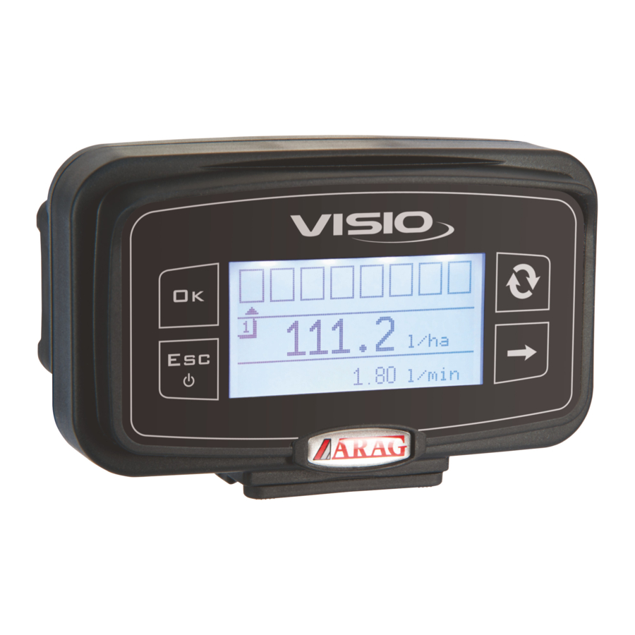
Summary of Contents for ARAG VISIO MULTIFLOW 4670611
- Page 1 DISPLAY FOR MULTICHANNEL FLOWMETER 4670611 Software rel. 1.2.x INSTALLATION, USE AND MAINTENANCE...
-
Page 2: Table Of Contents
SOMMARIO 1. INTRODUCTION ..................................................4 1.1 Product description ..........................................4 2. INTENDED USE ..................................................4 3. CONTENT OF THE PACKAGE ..............................................4 4. PRECAUTIONS ................................................... 4 5. INSTALLATION ................................................... 4 5.1 Risks and protections before assembly ....................................4 5.2 Positioning ............................................ - Page 3 This manual is an integral part of the equipment to which it refers and must accompany the equipment in case of sale or change of ownership. Keep it for any future reference; ARAG reserves the right to modify product specifications and instructions...
-
Page 4: Introduction
WHEN ARC WELDING IS REQUIRED, MAKE SURE THAT EQUIPMENT POWER IS SWITCHED OFF; DISCONNECT POWER CABLES IF NEEDED. ARAG is not liable for damage to the system, persons, animals or property caused by VISIO MULTIFLOW wrong or unsuitable assembly. Failure to observe the above instructions automatically voids the warranty. -
Page 5: Assembly Diagrams
Assembly diagrams Cod. 4670611.510 Legend: 1) Power cable 2) Speed sensor connection cables 3) ORION MULTIFLOW Flowmeters connection cables 4) ORION MULTIFLOW Flowmeters 5) Speed sensors and job status POWER SUPPLY + CANBUS SUPERSEAL™ TE 4-POLE CONNECTOR Position Connection +12 VDC CAN L CAN H... -
Page 6: Wiring Connections
• Use of unsuitable cables not provided by ARAG automatically voids the warranty. • ARAG is not liable for damages to the equipment, persons or animals caused by failure to observe the above instructions. General precautions for a correct harness position •... -
Page 7: Preliminary Setup
• Connector 1 controls the rows from 1 to 4; • Connector 2 controls the rows from 5 to 8; • Connector 3 controls the rows from 9 to 12; • Connector 4 controls the rows from 13 to 16. Preliminary setup 6.4.1 Multi flowmeter orientation... -
Page 8: Controls In The Menu
CONTROLS IN THE MENU First switching on At first switching on, VISIO MULTIFLOW will run a guided procedure allowing user to set the device's basic settings. Press to scroll through items, to save and move on to next setting, or to go back to previous setting. -
Page 9: Menu Structure
MENU STRUCTURE... -
Page 10: Preliminary Setup For Use - Setup Menu
PRELIMINARY SETUP FOR USE - SETUP MENU ALARMS 9.1.1 Flowrate alarms Set minimum and maximum flowrate thresholds for alarm message. Minimum and maximum rate alarms are set in the same way. 1) Open Alarm menu (Setup menu > Alarms). Alarms Min flowrate The display will show the current setting below the selected item. -
Page 11: Application Rate Alarms
9.1.3 Application rate alarms Set the desired alarm display thresholds for minimum and maximum application rate. Minimum and maximum application rate alarms are set in the same way. 1) Open Alarm menu (Setup menu > Alarms). Alarms Min speed The display will show the current setting below the selected item. Max speed Press to edit the selected menu item. -
Page 12: Sensors
SENSORS 9.2.1 Speed sensor Setup menu Alarms 1) Open Sensors menu (Setup menu > Sensors ). Sensors Options Sensors 1) Access the Speed sensor menu (Settings menu > Sensors > Speed sensor) to Speed sensor calibrate the sensor. Multiflow orient. 9.2.2 Speed sensor calibration VISIO MULTIFLOW calculates the information concerning the speed thanks to pulses received by the sensor installed on the wheel. -
Page 13: Automatic Calibration
9.2.4 Automatic calibration Calculate and save the wheel constant according to the procedure below: Speed sensor 1) Open automatic calibration menu (Setup menu > Sensors > Speed sensor > Auto Man. calibration Calibration). Auto calibration ¬ ¬ Constant calc. As soon as menu is open, the equipment is ready to start measuring with no further controls being required. -
Page 14: Job Setting
JOB SETTING Set the values corresponding to the machine. 9.3.1 Number of rows Set the number of rows you wish to use. Job settings 1) Access the row number set-up menu (Settings menu > Job set-up > Number of rows). Rows number The display will show the current value below the selected item. -
Page 15: Application Rate
9.3.3 Application rate Set the value of the desired application rate. 1) Access the application rate set-up menu Job settings (Settings menu > Job set-up > Application rate). Rows number Row width The display will show the current value below the selected item. Application rate Press to edit the application rate. -
Page 16: Options
OPTIONS 9.4.1 Language Set the desired language. Open language setting menu (Setup menu > Options > Language). Options Language The display will show the current value below the selected item. English Press to edit language. Units of measurem. Display contrast Language 1) Select a language through Italiano... -
Page 17: Speed Units Of Measurement
9.5.3 Speed units of measurement Open speed unit of measurement setting menu (Setup menu > Options > Units of Units of measurem. measurem. > Speed). Flowrate The display will show the current value below the selected item. Volume Speed Press to select speed unit of measurement. -
Page 18: Application Rate Units Of Measurement
9.5.6 Application rate units of measurement Open application rate unit of measurement setting menu (Setup menu > Options > Units Units of measurem. of measurem. > Application rate). Length The display will show the current value below the selected item. Surface Application Rate Press... -
Page 19: Display Contrast
DISPLAY CONTRAST Set display contrast. Open display contrast menu (Setup menu > Options > Display contrast). Options Language The display will show the current value below the selected item. Units of measurem. Press to edit the selected menu item. Display contrast 1) Set a value through Display contrast Every time you press it, value will increase by 5% up to 100%. -
Page 20: Display Settings
DISPLAY SETTINGS The main page shows the display divided into three horizontal parts. Every sector can be assigned the desired value. Options Open Display settings menu (Setup menu > Options > Display settings). Alarm tones Keytones Press to edit the selected menu item. Display settings Display settings 1) Select desired value through... -
Page 21: Setup Management
9.11 SETUP MANAGEMENT VISIO MULTIFLOW settings can be loaded from or saved on a USB pen drive in order to reconfigure it if required, fix problems or set another VISIO MULTIFLOW with no need to repeat all manual operations. Once installation is completed, and VISIO MULTIFLOW operation has been checked, we recommend to save all settings onto a USB pen drive. -
Page 22: Use
In the 3 areas of the monitor, VISIO MULTIFLOW will display the parameters set in the Display settings menu. 0.00 l 0.366 Press key several times to view a value in extended mode until value is on display 0.482 km central part. - Page 23 Press for two seconds to switch from the 3-display mode to the mode showing the situation of the rows of the connected flowmeters graphically (from 1 to 16). Pressing , the central area of the display will show the various speed, applicationrate and flowrate measurements in extended mode.
-
Page 24: Test
10.2 TEST This menu allows user to view some data and carry out an operation test of VISIO MULTIFLOW: - Firmware version: the display shows the firmware version installed. - Battery voltage: the display shows the power voltage of the device. 10.3 DISPLAY TEST Display test checks the device display correct operation. -
Page 25: Sensors Test
10.5 SENSORS TEST Sensors test checks correct operation of the sensors connected to the device. Sensores test Speed sensor External enable Multiflow Installation Multiflow 1 Status Power voltage Temperature Flowmeter 1 Flowrate Status code Error code Multiflow 2 Multiflow 3 Multiflow 4 Test Open sensors test menu (Setup menu >... -
Page 26: External Activation Test
10.5.2 External activation test Sensors Speed sensor The display shows the current external activation been in use. External enable Multiflow 10.5.3 Multi flowmeters test This menu allows to get information about each multi flowmeter and the corresponding flowmeters. Sensors Open Multi flowmeters test menu (Setup menu > Test > Sensors > Multi flowmeters). Speed sensor External enable Press... -
Page 27: Maintenance / Diagnostics / Repairs
MAINTENANCE / DIAGNOSTICS / REPAIRS • Clean only with a soft wet cloth. • Do not use aggressive detergents or products. • Do not clean equipment with direct water jets. 11.1 Troubleshooting FAULT CAUSE REMEDY No power supply Check power cable connections VISIO MULTIFLOW is off or does not switch on Device is OFF... -
Page 28: Setup Menu
GUARANTEE TERMS 1. ARAG s.r.l. guarantees this apparatus for a period of 360 days (1 year) from the date of sale to the client user (date of the goods delivery note). The components of the apparatus, that in the unappealable opinion of ARAG are faulty due to an original defect in the material or production process, will be repaired or replaced free of charge at the nearest Assistance Center operating at the moment the request for intervention is made. - Page 29 Notes...
- Page 30 Notes...
- Page 32 Only use genuine ARAG accessories or spare parts to make sure manufacturer guaranteed safety conditions are maintained in time. Always refer to ARAG spare parts catalog 42048 RUBIERA (Reggio Emilia) - ITALY Via Palladio, 5/A Tel. +39 0522 622011 Fax +39 0522 628944 www.aragnet.com...
Need help?
Do you have a question about the VISIO MULTIFLOW 4670611 and is the answer not in the manual?
Questions and answers