
Related Manuals for ARAG BRAVO 140 SERIES


Summary of Contents for ARAG BRAVO 140 SERIES
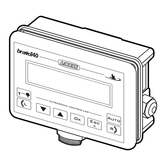
- Page 1 BRAVO 140 SERIES MONITOR 46714221 Software rel. 1.0x INSTALLATION, USE AND MAINTENANCE...
-
Page 2: Legend Symbols
This manual is an integral part of the equipment to which it refers and must accompany the equipment in case of sale or change of ownership. Keep it for future reference; ARAG reserves the right to modify the specifications and instructions regarding the product at any time and without prior notice. -
Page 3: Table Of Contents
CONTENTS • Legend symbols.......................2 • Foreword and guide to the manual .................5 • Using the manual ......................5 • Conventions ........................5 • Liability ..........................5 1 Risks and precautions before assembly ...............6 2 Intended use ........................6 3 Contents of the package ....................6 4 Location on the machine....................7 Recommended system configuration ...............7 Locating the monitor ....................7... - Page 4 10 Use ..........................20 10.1 Preliminary setup before application ..............20 10.2 Machine speed (simulated) ..................20 10.3 Row distance ......................20 10.4 Sensibility ......................21 10.5 Automatic operation ....................21 10.6 Manual operation ....................21 10.7 Spraying data ......................22 10.7 .1 Sprayed trees count ....................22 11 Maintenance / Diagnostics / Repairs ................23 11.1 Errors during operation ..................23 11.2...
-
Page 5: Foreword And Guide To The Manual
LIABILITY The installation technician is responsible for implementing the installation procedure in a professional manner so as to guarantee perfect functionality of the monitor, whether supplied solely with ARAG components or with components from other manufacturers. ARAG recommends using its own components for the installation of the control systems. -
Page 6: Risks And Precautions Before Assembly
RISKS AND PRECAUTIONS BEFORE ASSEMBLY All installation work must be done with the battery disconnected, using suitable tools and any individual protection equipment deemed necessary. Use ONLY clean water for treatment tests and simulations: using chemicals during simulated treatment runs can seriously injure persons in the vicinity. INTENDED USE BRAVO 14x is a sprayer monitor designed for leaf treatment, featuring many control functions that can be activated from the cabin. -
Page 7: Location On The Machine
LOCATION ON THE MACHINE Recommended system configuration Assembly diagram for orchard sprayers - BRAVO 14x 15/54 12Vdc Legend: Control panel Starter key Speed sensor US1÷US2 Ultrasonic sensors 1-2 Section valves Tab. 2 Locating the monitor BRAVO 14x series monitors must be installed in the cab of the tractor, in observance of the following precautions: - DO NOT install the monitor in an area subject to excessive vibration or collisions as this may damage it or lead to its controls being accidentally actuated. -
Page 8: Mounting The Bracket
Mounting the bracket The monitor must be mounted on a bracket installed at the desired location (the previous paragraph shows the bracket drilling template). The bracket must be extracted from its seat on the monitor (A, Fig. 1) and installed using the provided bolts (B). Make sure the bracket is securely mounted, fit the monitor or control unit to it, and push it in until it locks in place (C). -
Page 9: Power Connection
Power connection CAUTION: To avoid short circuits, do not connect the power cable connector before the installation is completed. Before powering up the monitor and control unit, make sure the battery voltage is as specified (12 Vdc). Bravo 14x is directly powered by the tractor battery (12 Vdc): ALWAYS switch on the monitor first; then remember to manually switch off the monitor by means of the suitable button onto the control panel. -
Page 10: Connecting The Cable To The Control Unit And Services
• Use of unsuitable cables or cables not provided by ARAG automatically voids the warranty. • ARAG is not liable for damage to the equipment, persons, animals or things caused by failure to observe the above instructions. Connecting the multi-pin connector Connect the multi-pin connector to the panel and connect the other end of its cable to the control unit. -
Page 11: Connecting The Sensors
Use ARAG sensors: use of unsuitable sensors or sensors not provided by ARAG automatically voids the warranty. ARAG is not liable for damage to the equipment, persons, animals or things caused by failure to observe the above instructions. The product comes with speed sensor connection instructions. -
Page 12: Ultrasonic Sensors
Ultrasonic sensors The monitor can only work when ultrasonic sensors (code 46713000.100 - sold sepa- rately) are connected. Always set sensors in front of leaves, at such a height that they can detect the wider area ( , Fig. 6a); avoid brushwood (Fig. 6b) or partial leaf coverage (Fig. 6c). Fig. -
Page 13: Mounting The Sensors To The Tractor
6.4.1 Mounting the sensors to the tractor After detecting sensor corret position according to tree height, install and secure them on the machine as described in the attached instruction sheet. CAUTION: the sensors must always be mounted parallel to the ground and perpendi- cular to the plant to be sprayed (Fig. -
Page 14: Distance Between Sensors And Rows
6.4.2 Distance between sensors and rows ARAG sensors (code 46713000.100) range is up to 6 m, and they can be adjusted by me- ans of the relevant buttons available on each sensor. Please refer to the manual supplied with the sensors for all adjusting procedures. -
Page 15: 7 Controls And Display
7 CONTROLS AND DISPLAY 7.1 Control panel Auto ULTRASONIC CONTROLLER Parameter selection or modification keys / Boom control keys Tab. 5 7.2 Control, selection and modification keys Sensitivity: spraying Manual / Automatic is changed accor- application ding to leaf volume Confirm data / ON/OFF Decrease / Increase /... -
Page 16: Menu Structure
MENU STRUCTURE Advanced Menu Spraying Menu Language Treated trees Unit of measure Area Speed sensor Wheel constant Dist.sens./sect. Power sup.alarm Tab. 8 ONLY if speed sensor is ENABLED. ADVANCED SETUP The monitor can be programmed with the parameters required to ensure correct distribution of the treatment product. -
Page 17: Monitor Power-Up / Shutdown
Monitor power-up / shutdown Spraying Normal power-up Menu Advanced Power-up for Advanced setup Menu Shutdown Tab. 9 Advanced menu Language Italiano, English, Español, Português DEF: Italiano Unit of measure • EU (l/ha, km/h, m, cm/imp) • US (gpa, mp , ft, in./pls DEF: EU Speed sensor •... -
Page 18: Language
Switch the monitor on to enter Advanced setup mode (Par. 9.2), and set the parame- ters below. Language Setting user’s language • Italiano Language • English • Espanol Italian • Portugues 1) Scroll the parameters and select Language. Auto ULTRASONIC CONTROLLER 2) Confirm. -
Page 19: Wheel Constant Manual Setting
9.7.1 Wheel constant manual setting Constant formula: distance travelled (cm) Kwheel = n° of measurement points x n° of wheel revolutions <distance travelled> distance in cm. covered by the wheel along Wheel constant measurement travel; 50.0 cm/imp <n° of measurement points> number of measurement points (e.g. -
Page 20: Use
10.1 Preliminary setup before application Before starting a treatment, a number of settings are required to ensure that the treatment is implemented correctly. Once the data have been entered, treatment can be started. Advanced Dedicated When Setting menu Par. • Wheel constant (speed sensor ENABLED) FIRST START-UP •... -
Page 21: Sensibility
10.4 Sensibility Set sensibility on distance A. Set value allows you to advance boom opening and delay its closing when tractor is close to the plant to be sprayed (Fig. 11). Sensibility 1) Press to edit sensibility. 2) Edit the value. 3) Confirm setting. -
Page 22: Spraying Data
10.7 Spraying data ---- Menu ---- --Spraying-- Auto ULTRASONIC CONTROLLER The following counters can be reset at any time 15.0 Km/h - Sprayed trees Delete? 25 Trs. 25 Trs. 15.0 Km/h - Sprayed surface Delete? 12.3 ha (Only when speed sensor is ENABLED) 12.3 ha Tree count is always displayed;... -
Page 23: Maintenance / Diagnostics / Repairs
MAINTENANCE / DIAGNOSTICS / REPAIRS 11.1 Errors during operation Speed alarm: It is only displayed during automatic operation A, when booms are enabled (A) and trees are detected (B), but the monitor does not detect machine speed. 11.2 Test Menu With this menu you can test monitor correct operation: all tests are reading-only, this means that it is not possible to edit data. -
Page 24: Troubleshooting
11.3 Troubleshooting FAULT CAUSE REMEDY Power supply missing • Check power supply cable connections. Display will not turn ON Computer is OFF • Press the ON button. • Check wiring connection and valve One valve will not open No power supply to valve operation. -
Page 25: Displayed Data And Units Of Measurement
12.2 Displayed data and units of measurement • Advanced Menu Datum Description Min. Max. Notes Language options: Language Display language Italiano, English, Español, Português Unit of Units of measurement Available options: measure used to display data EU, US Available options: Speed sensor Type Enabled, Disabled... -
Page 26: Guarantee Terms
GUARANTEE TERMS 1. ARAG s.r.l. guarantees this apparatus for a period of 360 day (1 year) from the date of sale to the client user (date of the goods delivery note). The components of the apparatus, that in the unappealable opinion of ARAG are faulty due to an original defect in the material or production process, will be repaired or replaced free of charge at the nearest Assistance Centre operating at the moment the request for intervention is made. - Page 27 C o n f o r m i t y D e c l a r a t i o n ARAG s.r.l. Via Palladio, 5/A 42048 Rubiera (RE) - Italy P.IVA 01801480359 Dichiara che il prodotto descrizione: Computer modello: Bravo 14X codice: 46714XXX risponde ai requisiti di conformità...
- Page 28 Only use original ARAG accessories and spare parts, to maintain safety conditions foreseen by the constructor. Always refer to the ARAG spare parts catalogue. 42048 RUBIERA (Reggio Emilia) - ITALY Via Palladio, 5/A Tel. +39 0522 622011 Fax +39 0522 628944 www.aragnet.com...
Need help?
Do you have a question about the BRAVO 140 SERIES and is the answer not in the manual?
Questions and answers