Hi-Force HVL Series Operating Instructions Manual

Hi-Force HVL Series Operating Instructions Manual

Single-acting, very low height pancake cylinders
Hide thumbs Also See for HVL Series:

Advertisement

Quick Links

This 'Original instructions' document assumes that the operator carrying out any operation with this
product is trained and competent to do so. This manual does not attempt to cover all details or variations
in the equipment. Nor does this manual claim to provide for every possible contingency met in connection
with the installation, operation, or maintenance thereof. Should further information be desired, or should
a particular problem arise which is not covered in sufficient detail, the matter should be referred to
Hi-Force.
OPERATING INSTRUCTION MANUAL
HVL SERIES | SINGLE-ACTING, VERY LOW HEIGHT
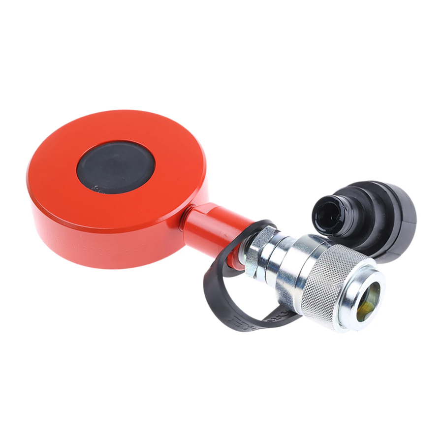
Hi-Force HVL Single-Acting, Very Low Height Pancake Cylinders are designed for use in narrow spaces
where a minimal colsed height is required. HVL cylinders are available in capacities ranging from 10 to 104
tonnes with all cylinders having a stroke length of 6mm. All cylinders have a maximum working pressure of
700 bar (10,000 psi). This manual applies to the Hi-Force HVL Single-Acting, Very Low Height Pancake
Cylinders ONLY. It contains the latest product information available at the time of publication and approval.
For information relating to the servicing of an HVL cylinder, see the servicing instructions, which are
available on the Hi-Force website. Hi-Force reserves the right to make changes to this document at any
time without notice.
Operating Instruction Manual:
PANCAKE CYLINDERS
1
OM-HVL-01
Serial Numbers:
From: AF0324

Advertisement

Table of Contents
loading
Need help?

Need help?

Do you have a question about the HVL Series and is the answer not in the manual?

Questions and answers

Summary of Contents for Hi-Force HVL Series

  • Page 1 Cylinders ONLY. It contains the latest product information available at the time of publication and approval. For information relating to the servicing of an HVL cylinder, see the servicing instructions, which are available on the Hi-Force website. Hi-Force reserves the right to make changes to this document at any time without notice.
  • Page 2: Table Of Contents

    Operating Instruction Manual: Serial Numbers: OM-HVL-01 From: AF0324 Table of Contents 1.0 Inspection upon Receipt ..............3 2.0 Safety Precautions ................3 3.0 Declaration of Incorporation / Conformity ........6 4.0 Component Identification ..............7 5.0 Installation / Setup ................8 6.0 Operation ..................
  • Page 3: Inspection Upon Receipt

    If in doubt on the correct use of any Hi-Force equipment, contact your nearest Hi-Force office or distributor. Only qualified personnel should be allowed to operate hydraulic equipment. If an operator has not been trained on high-pressure hydraulic equipment and its safe usage, consult your local Hi-Force sales office or distributor who can offer training courses for operators.
  • Page 4 NEVER attempt to solve, or clean-up leaks in the system while the system is pressurised.  Immediately replace any worn or damaged parts using genuine Hi-Force parts only.  DO NOT use any hydraulic equipment if you are under the influence of alcohol, drugs or medication.
  • Page 5 HVL hydraulic cylinders to operate at a maximum working pressure of 700 bar (10,000 psi). Overloading hydraulic cylinders can result in component failure and possible serious personal injury.  DO NOT connect a hydraulic pump with a higher pressure capacity rating to any Hi-Force cylinder of this model series. Good Practice: Use a pressure gauge to monitor the entire system.
  • Page 6: Declaration Of Incorporation / Conformity

    To protect your warranty, only use the hydraulic oil grades as specified in Section 8.1. 3.0 Declaration of Incorporation / Conformity Hi-Force declares that this product has been tested and complies with the standards and declarations as set out in the Declaration of Incorporation/Conformity (DoI/DoC). The DoI/DoC is included as Annex A to this instruction document and is supplied with all shipments of this product.
  • Page 7: Component Identification

    Operating Instruction Manual: Serial Numbers: OM-HVL-01 From: AF0324 4.0 Component Identification Clyinder Body Female Coupler Piston / Saddle Dust Cap Reducer (Excluding HVL100) Base Plate Figure 4.1: Component Identification...
  • Page 8: Installation / Setup

    Operating Instruction Manual: Serial Numbers: OM-HVL-01 From: AF0324 5.0 Installation / Setup 5.1 Pump Requirements Ensure that the hydraulic pump to be used is suitable for the cylinder/s to which it will connect. For a single-acting cylinder (one pressure coupling connection), a single-acting hydraulic pump fitted with either a 2-way or 3-way valve and a single, correctly rated hose, must be used.
  • Page 9 Operating Instruction Manual: Serial Numbers: OM-HVL-01 From: AF0324 5.3 Bleeding Trapped Air from the System The bleeding of trapped air from a hydraulic system must only be performed by qualified personnel who have been trained and are competent to do so. Cylinders and hoses are not always completely filled with oil when new.
  • Page 10: Operation

    Carry out basic maintenance on a regular basis to keep the cylinder operating in a trouble-free manner. Maintenance intervals are determined by the frequency of use and the operating conditions on site.  ALWAYS use Hi-Force specified hydraulic oil grades with the cylinders. The use of other fluids may invalidate your warranty. ...
  • Page 11: Specifications

    8.1 Oil Specifications Hi-Force tools will use 1 of 2 grades of oil, dependant on the pump used. The tools are designed to operate at temperatures between -20°C and 80°C. Details of the oil used can be found in the chosen Hi-Force pump’s operating manual, in the section: FILLING THE PUMP WITH OIL.
  • Page 12: Troubleshooting

    Serial Numbers: OM-HVL-01 From: AF0324 10.0 Troubleshooting The Hi-Force HVL electric-driven hydraulic pump should be serviced and repaired only by authorised Hi- Force repair centres. The following table gives possible causes and solutions for common problems. TROUBLESHOOTING GUIDE Problem Possible Cause Solution 1.
  • Page 13 Operating Instruction Manual: Serial Numbers: OM-HVL-01 From: AF0324 UK Head Office: Hi-Force Limited Prospect Way, Daventry, Northamptonshire NN11 8PL United Kingdom Tel: + 44 1327 301000 Fax: + 44 1327 706555 Email: daventry@hi-force.com www.hi-force.com GLOBAL BRAND. LOCAL SERVICE. Hi-Force Global offices: www.hi-force.com/en-uk/hi-force-offices...

This manual is also suitable for:

Hvl10Hvl20Hvl30Hvl50Hvl100

Table of Contents