Table of Contents
Advertisement
Quick Links
Advertisement
Chapters
Table of Contents

Related Manuals for Allen Engineering Corporation RAZORBACK RIDERS PRO1200C


Summary of Contents for Allen Engineering Corporation RAZORBACK RIDERS PRO1200C
- Page 2 Riding T rowel Riding T rowel OPERATIONS MANUAL PARTS BOOK PRINTED 5/05 PART #: 047115 Issue:1 Rev: 2 THIS MANUAL COVERS RIDING TROWEL(S) BELOW # 045898 # 045898 1200C NOL SHD 34VGTD 1200C NOL SHD 34VGTD # 046574 # 046574 1200C NOL SHD 34VGG 1200C NOL...
- Page 3 Engineering Corporation reserves the choice to repair or replace. 2. If Allen Engineering Corporation chooses to replace the part, it will be at no cost to the customer and will be made available to the Distributor/Dealer from whom the customer purchased the product.
- Page 4 OPERATIONS OPERATIONS IDENTIFICATION PLATE An identification plate listing the Model Number and Serial Number is attached to each unit and is located on the left side of the mainframe. The plate should not be removed. Please record the information found on this plate below so it will be available should the identification plate become lost or damaged .
-
Page 5: Table Of Contents
PRO 1200C Operating Information OPERATIONS TABLE OF CONTENTS Safety ..........1A-6 Laws Pertaining to Spark Arrestors . - Page 6 Important Reminder OPERATIONS Complete any warranty requirements as specified by the engine manufacturer in their instructions found inside the manual box on the back of the seat. Your engine and clutch is not manufactured by Allen Engineering Corp., and therefore is not covered under Allen Engineering warranty.
- Page 7 All unauthorized returns will be shipped back to the addressee at their expense. Keep this manual or a copy of it with the machine. If you loose this manual or need an additional copy please contact your Allen distributor or Allen Engineering Corporation at (800) 643-0095 © 2002 Allen Engineering Corp.
-
Page 8: Safety
OPERATIONS 1.1 Safety This manual contains NOTES, CAUTIONS and WARNINGS which must be followed to reduce the possibility of improper service damage to the equipment or personal injury. Read and follow all NOTES, CAUTIONS and WARNINGS included in this manual. NOTE Contains additional information important to a procedure. -
Page 9: Operating Safety
OPERATIONS 1.3 Operating Safety Familiarity and proper training are required for the safe operation of this equipment! Equipment operated improperly or by untrained personnel can be dangerous! Read the operating instructions contained in both this manual and the engine manual and familiarize yourself with the location and proper use of all controls. Safety Precautions 1. -
Page 10: Service Safety
OPERATIONS 1.4 Service Safety Poorly maintained equipment can become a safety hazard! In order for the equipment to operate safely and properly over a long period of time, periodic maintenance and occasional repairs are necessary. DO NOT attempt to clean or service machine while it is running. Rotating parts can cause severe injury. DO NOT crank a flooded engine with the spark plug removed. -
Page 11: Technical Data
OPERATIONS 1.6 Technical Data Standard Features: Dimensions (L x W x H) ........... . NOL-100”... -
Page 12: Description
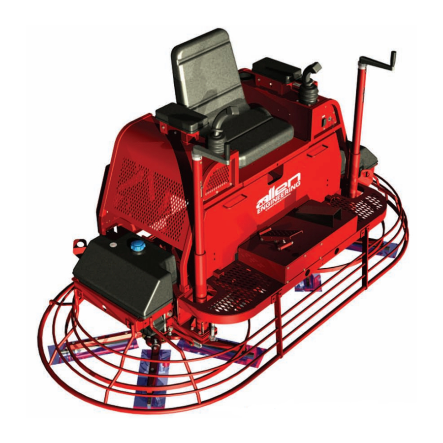
1.7 Description OPERATIONS The Riding Trowel is a modern high production machine. Finishing rate will vary depending on the operators skill and job conditions. This Riding Trowel has ten finishing blades. The Super Heavy Duty Gearboxes are designed to provide exceptional performance with low maintenance and trouble free use under some of the worst conditions. -
Page 13: Operating
OPERATIONS 1.10 Operating To utilize your Allen Engineering Razorback ® Rider to its fullest capacity the machine should be driven in the direction the operator is facing. This will finish the widest possible area while giving the operator an excellent view of the slab surface about to be troweled. -
Page 14: Steering
OPERATIONS 1.12 Steering A slight "feathering motion" forward and backward with the left hand joystick is required to move the machine in a straight path to the left or right while operating the right hand joystick. See illustration. forward reverse rotate clockwise rotate counter clockwise left sideways... -
Page 15: Periodic Maintenance Schedule
OPERATIONS 1.14 Periodic Maintenance Schedule The chart below list basic trowel and engine maintenance. Refer to engine manufacturer's Operation Manual for additional information on engine maintenance. A copy of the engine Operator's Manual was supplied with the machine when it was shipped. To service the engine pull the seat locking pin out and tilt seat back. DAILY EVERY 20 EVERY 50 EVERY 100 EVERY 300 HOURS... -
Page 16: Drive Belts
1.16 Drive Belts OPERATIONS To Replace 1. Remove screws from splash guard plate. 2. Remove belt from lower pulley, and then torque converter. 3. Loosen set screws(A) on both the u-joints where they couple to the drive shaft. (refer to fig. 2A) 4. -
Page 17: Control Linkage Lubrication
1.17 Control Lubrication OPERATIONS The control fulcrums are equipped with grease fittings to lubricate pivot points. Grease control fulcrums once a day or every 8 hours of operation to prevent wear and ensure free movement and smooth response of opera- tor joysticks. -
Page 18: Lift Lever Adjustment
1.18 Lift Lever Adjustment OPERATIONS Damage to or replacement of a trowel arm can change the adjustment of the lift lever. This can unbalance the trowel arms and cause the trowel to wobble during operation. To operate smoothly the lift lever on all arms must be adjusted the same to ensure that the trowel is balanced correctly. -
Page 19: Transporting Trowels
1.19 Transporting Trowel OPERATIONS Optional dolly jacks are available for short moves or to aid in servicing the trowel. Install dolly jacks as follows: 1. Inspect dolly jack for serviceability and damage. 2. Place riding trowel on firm level ground. 3. - Page 20 1.20 Battery Jump Start Procedure OPERATIONS Occasionally it may be necessary to jump start a weak battery. If jump starting is necessary the following pro- cedure is recommended to prevent starter damage, battery damage, and personal injury. Warning: Jump starting a battery incorrectly can cause the battery to explode resulting in severe personal injury or death.
- Page 21 1.21 Engine Safety OPERATIONS 1A-19...
-
Page 22: Engine Safety
1.21 Engine Safety (cont’d) OPERATIONS Adding Fuel in Gas Engines 1A-20... - Page 23 1.21 Engine Safety (cont’d) OPERATIONS Adding Fuel in Diesel Engines 1A-21...
- Page 24 PARTS INFORMATION PARTS TABLE OF CONTENTS Upper Unit Assembly ............2A-2 Control Panel Assembly .
-
Page 25: Upper Unit Assembly
UPPER UNIT ASSEMBLY PARTS IT E M P AR T # D E S CR IP T ION QT Y 010001 FSTN, HHCS 1/4-20 X 1/2 GR 5 010089 FSTN, LW 1/4 NOTE: All set screws used on PRO 1200C RIDERS have blue 032125 LIGHT SWITCH 034876... - Page 26 CONTROL PANEL ASSEMBLY PARTS IT E M P AR T # D E S CR IP T ION QT Y 010002 FSTN, HHCS 1/4-20 X 3/4 010089 FSTN, LW 1/4 010098 FSTN, NUT HEX 1/4-20 010570 FSTN, NUT HEX 10-32 (NOT SHOWN) 029473 HOURMETER, TINY TACH (GAS) 046819...
-
Page 27: Frame Assembly
FRAME ASSEMBLY PARTS IT E M P AR T # D E S CR IP T ION QT Y 010020 FSTN, HHCS 5/16-18 X 1 010036 FSTN, HHCS 3/8-16 X 1 010082 FSTN, FW 5/16 010100 FSTN, NUT HEX 5/16-18 010102 FSTN, NUT HEX 3/8-16 045957... - Page 28 TORQUE CONVERTER ASSEMBLY PARTS ILL. PART # DESCRIPTION QTY. 1....042281 ..CLUTCH DRIVER, TORQUE CONV (RT) ....1 2.
-
Page 29: Driveline Assembly
DRIVELINE ASSEMBLY PARTS 2A-6 Modified 6/14/07... -
Page 30: Steering Assembly
STEERING ASSEMBLY PARTS IT E M P AR T # D E S CR IP T ION QT Y 010036 FSTN, HHCS 3/8-16 X 1 GR 5 010051 FSTN, NUT HEX JAM 1/2-20 FINE 010054 FSTN, HHCS 7/16-14 X 1-1/2 010070 FSTN, HHCS 1/2-13 X 1-3/4 GR 5 010072... -
Page 31: Pitch Control Assembly
PITCH CONTROL ASSEMBLY PARTS Pitch Control Assembly Part #: 046827 IT E M P AR T # D E S CR IP T ION QT Y 015410 FSTN, RHMS 1/4-20 X 3/8 015747 PIN, ROLL 3/16 X 1-3/8 029812 BUSHING, SLIDE PITCH CONTROL 032115 KNOB,PITCH CONTROL HANDLE 040147... -
Page 32: Trowel Arm Assembly
TROWEL ARM ASSEMBLY PARTS IT E M P AR T # D E S CR IP T ION QT Y 010513 ALEMITE 1/4-28 STRAIGHT 015692 CAP, 1/4 GREASE FITTING GREASE 039685 BEARING, BALL THRUST EW2 DAILY 039686 CAP, SHD PRESSURE PLATE 039687 PLATE, SHD PRESSURE 201163... - Page 33 SUPER HEAVY DUTY (SHD) GEARBOX PARTS LEFT HAND SITTING ON MACHINE(SOM) PART#: 046794 2A-10...
- Page 34 (SHD) GEARBOX LEFT HAND (SOM) PARTS PART#: 046794 (cont’d) 2A-11...
- Page 35 SUPER HEAVY DUTY (SHD) GEARBOX PARTS RIGHT HAND SITTING ON MACHINE(SOM) PART#: 046795 2A-12...
- Page 36 SHD GEARBOX RIGHT HAND SOM PARTS PART#: 046795 (cont’d) 2A-13...
- Page 37 RIGHT HAND SPIDER ASSEMBLY (SOM) PARTS IT E M P AR T # D E S CR IP T ION QT Y 010024 FSTN, HHCS 5/16-18 X 2 GR 5 010090 FSTN, LW 5/16 015677 FSTN, RING RETAINING (E-CLIP) 015678 FSTN, PIN YOKE ARM 7-3/8X7/16 015693 PLUG, PLASTIC CAP EC12...
- Page 38 LEFT HAND SPIDER ASSEMBLY (SOM) PARTS IT E M P AR T # D E S CR IP T ION QT Y 010024 FSTN, HHCS 5/16-18 X 2 GR 5 010090 FSTN, LW 5/16 015677 FSTN, RING RETAINING (E-CLIP) 015678 FSTN, PIN YOKE ARM 7-3/8 X 7/16 015691 FSTN, SHCS 1/2-13 X 1-1/2 RH...
-
Page 39: Offset Alignment Tutorial
OFFSET ALIGNMENT TUTORIAL (1 of 3) PARTS 2A-18... - Page 40 OFFSET ALIGNMENT TUTORIAL (2 of 3) PARTS 2A-19...
- Page 41 OFFSET ALIGNMENT TUTORIAL (3 of 3) PARTS 2A-20...
- Page 42 FOOT SPEED ASSEMBLY PARTS IT E M P AR T # D E S CR IP T ION QT Y 010002 FSTN, HHCS 1/4-20 X 3/4 010021 FSTN, HHCS 5/16-18 X 1-1/4 GR5 010046 FSTN, HHCS 3/8-16 X 3-1/2 010098 FSTN, NUT HEX 1/4-20 010100 FSTN, NUT HEX 5/16-18...
-
Page 43: Engine Mount Assembly (Gas)
ENGINE MOUNT ASSEMBLY (GAS) PARTS IT E M P AR T # D E S CR IP T ION QT Y 046710 MUFFLER EXTENSION 038728 MUFFLER 047078 MUFFLER MOUNT BRACKET 046812 REAR MOTOR MOUNT PLATE 046805 MOTOR PLATE BREATHER 039002 BREATHER MOUNT PLATE 046811 FRONT MOTOR MOUNT PLATE (NOT SHOWN) -
Page 44: Engine Mount Assembly (Diesel)
ENGINE MOUNT ASSEMBLY (DIESEL) PARTS IT E M P AR T # D E S CR IP T ION QT Y 047075 MUFFLER EXTENSION 046705 MUFFLER MOUNT BRACKET 038728 MUFFLER 046812 REAR MOTOR MOUNT PLATE 046805 MOTOR PLATE 046804 PUMP MOUNTING PLATE 046808 PUMP ADJUSTMENT ROD 046550... - Page 45 ACCESSORIES SUPER PRO SERIES DOLLY JACK SYSTEM -- SET PART # 039090 PARTS ILL. PART# DESCRIPTION QTY. 1...040637 ... .FSTN, HHCS 3/8-16 x 2 1/4 GRADE 8 ... . .8 2.
- Page 46 PARTS 1200-5 SERIES FLOATING DISCS (PANS) PART #: 040904-2 PRO SERIES LIFTING BRIDLE (SLING TYPE) NEW!!!!! 1200-5 SERIES PART #: 035461 COMPO-DISK PART #: 045901 Patent Pending SPIDER TROWEL ARM PULLER ALIGNMENT JIG ASSEMBLY (BOSS NOT INCLUDED) PART #: 016863 PART #: 045399 2A-29...
- Page 47 9910 FLOATING DISKS PUSH AND TOW CARTS STEEL MAGIC SCREEDS COMPODISK ® DIAMOND HEAD GRINDERS WORK BRIDGES Allen Engineering Corporation Allen Engineering Corporation .O. Box 819 .O. Box 819 Paragould, AR 72451-0819 Paragould, AR 72451-0819 (870) 236-7751 or (800) 643-0095 (870) 236-7751 or (800) 643-0095 .alleneng.com...
Need help?
Do you have a question about the RAZORBACK RIDERS PRO1200C and is the answer not in the manual?
Questions and answers