Table of Contents
Advertisement
Quick Links
OPERATIONS
PARTS
PRINTED 9/00
THIS MANUAL COVERS RIDING TROWEL(S) BELOW
M M
O O
D D
E E
L L
M M
O O
D D
E E
L L
1200 OL
1200 OL
1200 OL
1200 OL
1200 NOL
1200 NOL
1200 NOL
1200 NOL
Allen Engineering's Razorback Riding Trowels are covered under one or more of the following patent numbers: U.S. Design Patents: 323,510;
340,340; 344,736; 400,542; 402,998; 402,999; 403,332; 410,931. U.S. Utility Patents: 5,108,220; 5,238,323; 5,480,257; 5,480,258; 5,613,801;
5,685,667; 5,803,658; 5,816,739; 5,890,833; 5,934,823; 5,967,696; 5,988,938; 6,048,130; 6,053,660; 6,089,786. Candian Patents: 2,039,893.
French Patents: 0293496. German Patents: M9007736.9 With other Patents Pending.
SD 24LM
SD 24LM
SD 31VG
SD 31VG
SD 24LM
SD 24LM
SD 31VG
SD 31VG
Riding T
Riding T
OPERATIONS
PARTS
rowel
rowel
# 032076
# 032076
# 038809
# 038809
# 032034
# 032034
# 038722
# 038722
Advertisement
Table of Contents

Related Manuals for Allen Engineering Corporation 1200 OL 1200 OL SD 24LM SD 24LM


Summary of Contents for Allen Engineering Corporation 1200 OL 1200 OL SD 24LM SD 24LM
- Page 1 Riding T rowel Riding T rowel OPERATIONS OPERATIONS PARTS PARTS PRINTED 9/00 THIS MANUAL COVERS RIDING TROWEL(S) BELOW 1200 OL SD 24LM # 032076 1200 OL SD 24LM # 032076 1200 OL SD 31VG # 038809 1200 OL SD 31VG # 038809 1200 NOL SD 24LM...
- Page 2 Engineering Corporation reserves the choice to repair or replace. 2. If Allen Engineering Corporation chooses to replace the part, it will be at no cost to the customer and will be made available to the Distributor/Dealer from whom the customer purchased the product.
- Page 3 OPERATIONS OPERATIONS IDENTIFICATION PLATE An identification plate listing the Model Number and Serial Number is attached to each unit and is located on the left side of the mainframe. The plate should not be removed. Please record the information found on this plate below so it will be available should the identification plate become lost or damaged .
-
Page 4: Table Of Contents
PRO 1200 SD Operating Information OPERATIONS TABLE OF CONTENTS Safety Note ......... . .1A-6 Laws Pertaining to Spark Arrestors . - Page 5 Important Reminder OPERATIONS Complete any warranty requirements as specified by the engine manufacturer in their instructions found inside the battery box. Your engine and clutch is not manufactured by Allen Engineering Corp., and therefore is not covered under Allen Engineering warranty. Your engine manufacturer should be contacted if you wish to purchase a parts manual or a repair manual for your engine.
- Page 6 Keep this manual or a copy of it with the machine. If you loose this manual or need an additional copy please contact your Allen distributor or Allen Engineering Corporation at (800) 643-0095 and order lit- erature part number 039949.
-
Page 7: Safety Note
OPERATIONS 1.1 Safety Notes This manual contains NOTES, CAUTIONS and WARNINGS which must be followed to reduce the possibility of improper service damage to the equipment or personal injury. Read and follow all NOTES, CAUTIONS and WARNINGS included in this manual. NOTE Contains additional information important to a procedure. -
Page 8: Operating Safety
OPERATIONS 1.3 Operating Safety Familiarity and proper training are required for the safe operation of this equipment! Equipment operated improperly or by untrained personnel can be dangerous! Read the operating instructions contained in both this manual and the engine manual and familiarize yourself with the location and proper use of all controls. Safety Precautions 1. -
Page 9: Service Safety
OPERATIONS 1.4 Service Safety Poorly maintained equipment can become a safety hazard! In order for the equipment to operate safely and properly over a long period of time, periodic maintenance and occasional repairs are necessary. DO NOT attempt to clean or service machine while it is running. Rotating parts can cause severe injury. DO NOT crank a flooded engine with the spark plug removed. -
Page 10: Technical Data
OPERATIONS 1.6 Technical Data Standard Features: Dimensions (L x W x H) ........... . OL-92”... -
Page 11: Description
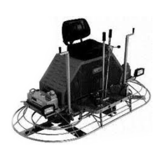
OPERATIONS 1.7 Description The Riding Trowel is a modern high production machine. Finishing rate will vary depending on the operators skill and job conditions. The Riding Trowel has eight finishing blades. The Super Duty Gearboxes are designed to provide exceptional performance with low maintenance and trouble free use under some of the most worse conditions. -
Page 12: Operating
OPERATIONS 1.10 Operating To utilize your Allen Engineering Razorback ® Rider to its fullest capacity the machine should be driven in the direction the operator is facing. This will finish the widest possible area while giving the operator an excellent view of the slab surface about to be troweled. -
Page 13: Steering
OPERATIONS 1.12 Steering A slight "feathering motion" forward and backward with the left hand control lever is required to move the machine in a straight path to the left or right while operating the right hand control lever. See illustration. forward reverse rotate clockwise... -
Page 14: Periodic Maintenance Schedule
OPERATIONS 1.14 Periodic Maintenance Schedule The chart below list basic trowel and engine maintenance. Refer to engine manufacturer's Operation Manual for additional information on engine maintenance. A copy of the engine Operator's Manual was supplied with the machine when it was shipped. To Service the engine pull the seat locking pin out and tilt seat back. DAILY EVERY 20 EVERY 50 EVERY 100 EVERY 300 HOURS... -
Page 15: Drive Belts
1.16 Drive Belts OPERATIONS KAWASAKI ENGINE To Tighten Belts REFERENCE ONLY 1. Loosen the jam nuts (E) located on the adjustment bolts (B). 2. Tighten the engine plate adjustment bolts (B) an equal number of turns until correct belt tension is obtained. Maximum belt play should be from 1/2 to 3/4"... -
Page 16: Control Linkage Lubrication
1.17 Control Linkage Lubrication OPERATIONS The control linkage is equipped with seven grease fittings to lubricate pivot points. Grease control linkage once a week or every 20 hours to prevent wear and ensure free movement and smooth response of control levers. -
Page 17: Lift Lever Adjustment
1.20 Lift Lever Adjustment OPERATIONS Damage to or replacement of a trowel arm can change the adjustment of the lift lever. This can unbalance the trowel arms and cause the trowel to wobble during operation. To operate smoothly the lift lever on all arms must be adjusted the same to ensure that the trowel is balanced correctly. -
Page 18: Transporting Trowels
1.21 Transporting Trowel OPERATIONS Optional dolly jacks are available for short moves or to aid in servicing the trowel. Install dolly jacks as follows: 1. Inspect dolly jack for serviceability and damage. 2. Place riding trowel on firm level ground. 3. - Page 19 1.22 Battery Jump Start Procedure OPERATIONS Occasionally it may be necessary to jump start a weak battery. If jump starting is necessary the following pro- cedure is recommended to prevent starter damage, battery damage, and personal injury. Warning: Jump starting a battery incorrectly can cause the battery to explode resulting in severe personal injury or death.
- Page 20 PARTS INFORMATION PARTS TABLE OF CONTENTS Frame Assembly ............. . .2A-2 Driveline Assembly .
- Page 21 FRAME ASSEMBLY PARTS ILL. PART # DESCRIPTION QTY. 1.....037769 ..SEAT W/ GLIDES ..........1 2.
- Page 22 DRIVELINE ASSEMBLY PARTS ILL. PART # DESCRIPTION QTY. 1....010307 ..KEY, 1/4” X 2” ........2 2.
- Page 23 ENGINE MOUNT SYSTEM PARTS LINAMAR VANGUARD 2A-4...
- Page 24 ENGINE MOUNT SYSTEM Cont’d PARTS LINAMAR ENGINE MOUNTING SYSTEM PARTS LIST ILL. PART # DESCRIPTION QTY. 1....010002 ..FSTN, HHCS 1/4-20 X 3/4 ......2 2.
- Page 25 CLUTCH ASSEMBLY PARTS ENGINE SHOWN AS REFERENCE ONLY ILL. PART # DESCRIPTION QTY. 1....026992 ..KEY ..........1 2.
- Page 26 CROSSHEAD AND PIVOT BOX ASSEMBLY PARTS ILL. PART # DESCRIPTION QTY. 1....026238 ..INSERT, CONTROL ARM ......2 2.
- Page 27 SUPER DUTY (SD) GEARBOX PARTS RIGHT HAND SITTING ON MACHINE(SOM) PART#: 029141 2A-8...
- Page 28 (SD) GEARBOX RIGHT HAND (SOM) PARTS PART#: 029141 (cont’d) ILL. PART # DESCRIPTION QTY. 1....010513 ..GREASE SERT 1/4-28 ........1 2.
- Page 29 SUPER DUTY (SD) GEARBOX PARTS LEFT HAND SITTING ON MACHINE(SOM) PART#: 029142 2A-10...
- Page 30 SD GEARBOX LEFT HAND SOM PARTS PART#: 029142 (cont’d) ILL. PART # DESCRIPTION QTY. 1....010513 ..GREASE SERT 1/4-28 ........1 2.
- Page 31 FUEL SYSTEM ASSEMBLY PARTS 2A-12...
- Page 32 FUEL SYSTEM ASSEMBLY (cont’d) PARTS ILL. PART # DESCRIPTION QTY. 1....028243 ..THROTTLE CABLE 52” HD (LINAMAR) ....1 .
- Page 33 ELECTRICAL COMPONENTS PARTS 2A-14...
- Page 34 ELECTRICAL COMPONENTS (cont’d) PARTS ILL. PART # DESCRIPTION QTY. 1....029303 ..4 LIGHT WIRING HARNESS ......1 2.
- Page 35 VANGUARD WIRING DIAGRAM PARTS 2A-16...
- Page 36 VANGUARD CONTROL PANEL ASSEMBLY PARTS ILL. PART# DESCRIPTION QTY. 1... . .034613 ....LENS, GREEN ........1 2.
- Page 37 PITCH CONTROL ASSEMBLY PARTS 2A-18...
- Page 38 PITCH CONTROL ASSEMBLY (cont’d) PARTS ILL. PART # DESCRIPTION QTY. 1....032115 ..KNOB, PITCH CONTROL ......1 2.
- Page 39 STEERING LEVER ASSEMBLY PARTS 2A-20...
- Page 40 STEERING LEVER ASSEMBLY (cont’d) PARTS ILL. PART # DESCRIPTION QTY. 1..018510 ..GREASE FITTING 1/4-28 x 45 DEG... . . 1 2.
- Page 41 SPRAY SYSTEM ASSEMBLY PARTS 2A-22...
- Page 42 SPRAY SYSTEM ASSEMBLY (cont’d) PARTS ILL. PART # DESCRIPTION QTY. 1...012705 ... .CAP, BRASS CP1325 ......2 2.
- Page 43 SPIDER ASSEMBLY PARTS 2A-24...
- Page 44 SPIDER ASSEMBLY (cont’d) PARTS ILL. PART # DESCRIPTION QTY. 1...012612 ... .NUT, HEX SELFLOCK 5/16-18 ....1 2.
- Page 45 ACCESSORIES PARTS CRUISE CONTROL KIT PART# 028848 ILL. PART# DESCRIPTION QTY. 1... .010018 ... . .BOLT, 5/16-18 x 1/2 ......2 2.
- Page 46 ACCESSORIES (cont’d) PARTS PRO DOLLY JACK SYSTEM -- SET PART # 027684 ILL. PART# DESCRIPTION QTY. 1...010040 ... .BOLT, 3/8-16 x 2 .......8 2.
- Page 47 ACCESSORIES (cont’d) PARTS PRO 1200 RIDING TROWEL VINYL COVER PART #: 026595 1200 FLOATING DISCS (PANS) PART #: 026912-2 (SET OF TWO) LIFTING BRIDLE (SLING TYPE) PART #: 035461 TROWEL ARM ALIGNMENT JIG PART #: 016863 SPIDER PULLER ASSEMBLY PART #: 035688 2A-28...
Need help?
Do you have a question about the 1200 OL 1200 OL SD 24LM SD 24LM and is the answer not in the manual?
Questions and answers