Advertisement
Quick Links
INTERFACE FEATURES
• 15 Band graphic EQ
• 4 inputs and 6 individually assignable outputs
• Independent equalization for front, rear, and sub
• Independent crossover for front, rear, and sub
• Selectable slope (12, 24, 36, or 48db per octave)
• Front and rear channels can be delayed independently up to 10ms
• Easy behind the radio installation in most applications
• Water resistant enclosure with zip tie mounts included
• Can be used with OE and aftermarket radios
• Chime control for GM/Chrysler vehicles
• Clipping detection and limiting circuits
AxxessInterfaces.com
Axxess 6-Channel Digital Signal Processor
with Water Resistant Enclosure
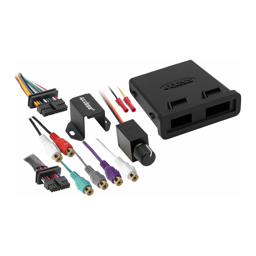
INTERFACE COMPONENTS
• AXDSP-L circuit board
• AXDSPL-WR harness (16-pin & 20-pin, with gaskets)
• AXDSPL-WR enclosure
• Case
• Cap (with O-ring)
• Internal header port for adding a Bluetooth interface module
• Bass knob included
• Retains OE voice prompts (SYNC® and OnStar®)
• Retains factory chimes including parking sensor and cross path
detection alerts
• Settings adjusted via Bluetooth® in a smart device application (tablet
or mobile phone), compatible with both Android and Apple devices
• Read, write, and store configurations for future recall
• Password protect feature available in the mobile app
• Micro-B USB updatable
© COPYRIGHT 2020 METRA ELECTRONICS CORPORATION
AXDSPL-WR
I N S T A L L A T I O N I N S T R U C T I O N S
TABLE OF CONTENTS
Preface ....................................................................2
Installation Options ...............................................2
Installation ......................................................... 3-4
Connections ........................................................5-6
AXDSPL-BT Installation ..........................................7
Mobile App ........................................................ 8-17
Pinout ....................................................................18
Specifications ....................................................... 19
TOOLS & INSTALLATION ACCESSORIES REQUIRED
• Crimping tool and connectors, or solder gun,
solder, and heat shrink • Tape • Wire cutter
• Zip ties • Multimeter
Apple App Store
Google Play Store
iOS 12.1 or higher
REV. 11/3/20 INSTAXDSPL-WR
Advertisement

Related Manuals for Axxess AXDSPL-WR


Summary of Contents for Axxess AXDSPL-WR
-
Page 1: Table Of Contents
Installation Options ..........2 Installation ............3-4 INTERFACE COMPONENTS Connections ............5-6 • AXDSP-L circuit board AXDSPL-BT Installation ..........7 • AXDSPL-WR harness (16-pin & 20-pin, with gaskets) Mobile App ............8-17 • AXDSPL-WR enclosure Pinout ..............18 • Case Specifications ............19 • Cap (with O-ring) INTERFACE FEATURES TOOLS & INSTALLATION ACCESSORIES REQUIRED... -
Page 2: Preface
The interface can grow as your stereo system grows. Start off by adding a subwoofer, The AXDSPL-WR interface can be used with an aftermarket radio to improve the overall listening experience for car audio enthusiasts. Installers will connect the RCA inputs from the interface to then add on from there. -
Page 3: Installation
2. With the arrow stamped onto the cap facing upwards, push the 16-pin connector from the AXDSPL-WR harness harness into the left side of the cap. The locking clip on the Zip-tie Mounts Case connector should face upward. - Page 4 INSTALLATION (CONT.) 6. Download and install the AXDSP-X app from the Google Play Store or Apple App Store. 7. Open the app then select the Bluetooth Connection tab. Follow the instructions to pair the mobile device to the interface. Refer to page 9 for more information. (Figure B) 7.
-
Page 5: Connections
AFTERMARKET RADIO SYSTEM Aftermarket Radio Bass Knob Do not use amp turn-on from aftermarket radio! Rear Front Black - Chassis Ground Orange - Control Wire Do Not Use Black - Chassis Ground An SPDT relay, Metra part number Yellow - Battery Power E-123, must be used if more than RCA Jacks Red - Accessory Power... - Page 6 STAND-ALONE BLUETOOTH SYSTEM ABK-1 Bass Knob (sold separately) Black - Chassis Ground Black - Chassis Ground Brown - Control Wire Orange - Control Wire Do Not Connect Black - Chassis Ground An SPDT relay, Metra part number Yellow - Battery Power E-123, must be used if more than RCA Jacks Red - Accessory Power...
-
Page 7: Axdspl-Bt Installation
16-Pin Header AXBK-1 (sold separately) can be used to control the volume. AX-DSPL-BT Note: The bass knob included with the AXDSPL-WR can also be used if it will not be used to control a subwoofer. 1. Important! Unplug the AXDSPL-WR from the vehicle. -
Page 8: Mobile App
MOBILE APP Setup Instructions The AXDSPL-WR uses the same app as the AXDSP-X. Only items pertaining to the AXDSPL-WR will be shown. • General information tab for installing the interface. Continued on the next page... - Page 9 MOBILE APP (CONT.) Bluetooth Connection • Scan - Press this button to start the Bluetooth pairing process, then select the interface once it is found. “Connected” will appear in the top left corner of the app once paired. Note: The interface must be powered during this process. •...
- Page 10 MOBILE APP (CONT.) Configuration • Identify - Click this button to confirm that the interface is connected properly. If so, a chime will be heard from the front left speaker*. * Only installations where the interface is connected to a front left speaker. •...
- Page 11 MOBILE APP (CONT.) Configuration (Cont.) • About - Displays information about the app, vehicle, interface, and mobile device. • Set Password - Assign a 4-digit password to lock the interface. If no password is desired, use “0000”. This will clear out any currently set password.
- Page 12 MOBILE APP (CONT.) Outputs Output Channels • Location - Location of speaker. • Group - Used to join channels together for simple equalization. Example, left front woofer/midrange and left front tweeter will be considered simply left front. The letter M denotes the speaker assigned as the master speaker.
- Page 13 MOBILE APP (CONT.) Crossover Adjust • If installing a subwoofer, the front and rear outputs will default to a 100Hz high pass filter to keep the low frequency signals out. If a subwoofer is not being installed, change the front and rear crossover points down to 20Hz for a full range signal, or to the lowest frequency the speakers will play down to.
- Page 14 MOBILE APP (CONT.) Equalizer Adjust • The front, rear, and sub channels can be adjusted independently within this tab with 15 bands of equalization available. It is best to tune this by using an RTA (Real Time Analyzer). • The Gain slider on the far left is for the channel selected. Continued on the next page...
- Page 15 MOBILE APP (CONT.) Delay Adjust • Allows a delay of each channel. If a delay is desired, first measure the distance (in inches) from each speaker to the listening position, then enter those values to the corresponding speaker. Add (in inches) to the desired speaker to delay it.
- Page 16 MOBILE APP (CONT.) Inputs/Levels • Chime Volume - Allows the factory warning chimes to be adjusted up or down when interfacing factory systems. Note: In newer Ford vehicles chimes will be heard through the gauge cluster if the factory amp is removed Continued on the next page...
- Page 17 MOBILE APP (CONT.) Locking Down Data Last and the most important. You must lock down your configuration!!! REV. 11/3/2020 INSTAXDSPL-WR...
-
Page 18: Pinout
PINOUT Input 6 - N/A Black - Chassis Ground Input 5 - N/A Pink - CAN-HI Purple RCA Jack - Rear Right Input * Blue/Pink - CAN-LO Blue/White - Amp Turn-On RCA Jack 1 - User Assignable Output Green RCA Jack - Rear Left Input * Brown - Control Wire for BT Volume Knob Red/White - Future Use RCA Jack 2 - User Assignable Output Gray RCA Jack - Front Right Input *... -
Page 19: Specifications
SPECIFICATIONS Input Impedance 1M Ohm Operating Voltage 10-16-volts DC Input Channels Standby Current Draw Input Options High-level or Low-level selectable Operation Current Draw 150mA Input Type Differential-Balanced Adjustments/Controls Application via Bluetooth Input Voltage Remote Output 12-volts DC (signal sense or with ignition) 0 - 28-volts (peak-to-peak) High Level Range Input Voltage... - Page 20 AXDSPL-WR I N S T A L L A T I O N I N S T R U C T I O N S Having difficulties? We’re here to help. Contact our Tech Support line at: 1-800-253-TECH Or via email at: techsupport@metra-autosound.com...
Need help?
Do you have a question about the AXDSPL-WR and is the answer not in the manual?
Questions and answers