Nortel BayStack 425-24T Manual
Hide thumbs
Also See for BayStack 425-24T:
- Installing (14 pages) ,
- Specifications (11 pages) ,
- Specification (2 pages)

Related Manuals for Nortel BayStack 425-24T


Summary of Contents for Nortel BayStack 425-24T
- Page 1 Part No. 215658-B July, 2004 4655 Great America Parkway Santa Clara, CA 95054 Installing the BayStack 425 Switch *215658B*...
- Page 2 In the interest of improving internal design, operational function, and/or reliability, Nortel Networks Inc. reserves the right to make changes to the products described in this document without notice. Nortel Networks Inc. does not assume any liability that may occur due to the use or application of the product(s) or circuit layout(s) described herein.
- Page 3 EN 55 022 statements This is to certify that the Nortel Networks BayStack 425 switch is shielded against the generation of radio interference in accordance with the application of Council Directive 89/336/EEC. Conformity is declared by the application of EN 55 022 Class A (CISPR 22).
- Page 4 EN 60 950 statement This is to certify that the Nortel Networks BayStack 425 switch is in compliance with the requirements of EN 60 950 in accordance with the Low Voltage Directive. Additional national differences for all European Union countries have been evaluated for compliance.
- Page 5 200 - 240 VAC 12 A 50 to 60 Hz Nortel Networks Inc. software license agreement This Software License Agreement (“License Agreement”) is between you, the end-user (“Customer”) and Nortel Networks Corporation and its subsidiaries and affiliates (“Nortel Networks”). PLEASE READ THE FOLLOWING CAREFULLY.
- Page 6 “Software” is owned or licensed by Nortel Networks, its parent or one of its subsidiaries or affiliates, and is copyrighted and licensed, not sold. Software consists of machine-readable instructions, its components, data, audio-visual content (such as images, text, recordings or pictures) and related licensed materials including all whole or partial copies. Nortel Networks grants you a license to use the Software only in the country where you acquired the Software.
- Page 7 Neither party may bring an action, regardless of form, more than two years after the cause of the action arose. The terms and conditions of this License Agreement form the complete and exclusive agreement between Customer and Nortel Networks. This License Agreement is governed by the laws of the country in which Customer acquires the Software. If the Software is acquired in the United States, then this License Agreement is governed by the laws of the state of New York.
- Page 8 215658-B...
- Page 9 Note: On the BayStack 425-48T switch, ports 49 and 50 can be configured either as SFP GBIC ports or as 10/100/1000 ports. Similarly, on the BayStack 425-24T switch, ports 25 and 26 can be configured either as SFP GBIC ports or as 10/100/1000 ports.
-
Page 10: Table Of Contents
This guide includes information about the following topics: • “Before you begin” (next) • “Package contents for the BayStack 425 switch” on page 9 • “Installing the switch on a table or shelf” on page 10 • “Installing the switch in an equipment rack” on page 11 •... -
Page 11: Package Contents For The Baystack 425 Switch
Package contents for the BayStack 425 switch Figure 1 Shows the Package contents for the BayStack 425 switch B a y S t a c k 11101FA 1. BayStack 425 2. Rack-mounting hardware: • Rack-mount brackets • Screws for attaching brackets to the switch •... -
Page 12: Installing The Switch On A Table Or Shelf
Installing the switch on a table or shelf You can install a single BayStack 425 on any flat surface that can safely support the weight of the switch and attached cables totaling 10 to 15 pounds (4.5 to 6.8 kilograms). 11102FA Attach the rubber feet at the marked locations. -
Page 13: Installing The Switch In An Equipment Rack
Installing the switch in an equipment rack Required tool: #2 Phillips screwdriver for attaching brackets to the switch. Rack requirements: • A space of 1.75 inches is provided for each switch in an EIA or IEC standard 19-inch (48.2-centimeter) equipment rack. •... -
Page 14: Connection Requirements
Connection requirements Required cables: 10/100BASE-T ports: For 10 Mb/s operation: Category 3, 4, or 5 UTP cable with an RJ-45 connector. For 100 Mb/s operation: Category 5 UTP cable with an RJ-45 connector. For 1000 Mb/s operation: Category 5 UTP cable with an RJ-45 connector. Console Port: Serial Cable with DB-9 female connector on one end. - Page 15 Figure 3 Pin assignments for the 1000BASE-T MDI and 1000BASE-T MDI-X Configurations Signal for 1000BASE-T MDI Signal for 1000BASE-T MDI-X Connector Pin number Configuration Configuration TP0+ TP1+ TP0- TP1- TP1+ TP0+ TP2+ TP3+ 87654321 TP2- TP3- 9464EA TP1- TP0- TP3+ TP2+ TP3- TP2-...
-
Page 16: Connecting Ac Power
Figure 4 Pin assignments in the console port Connector Pin number Signal Transmit data (TXD) Receive data (RXD) Signal ground (GND) 1, 4, 6, 7, 8, 9 Not used 9473EA Connecting AC power Required cable: AC power cord that meets the requirements of your local electrical code. - Page 17 Table 2 International power cord specifications (continued) Country/plug description Specifications Typical plug United Kingdom: 240 VAC • BS1363 male plug with fuse 50 Hz Single phase • Harmonized cord 229FA Australia: 240 VAC • AS3112-1981 male plug 50 Hz Single phase 230FA Table 3 AC Power specifications...
- Page 18 Back panel The switch back panel is shown in Figure Table 4 describes the components on the back panel. Figure 5 BayStack 425 back panel Cascade Down 100-240 V- 50-60Hz 2A 11110EA Table 4 Components on the BayStack 425 back panel Item Description AC power receptacle...
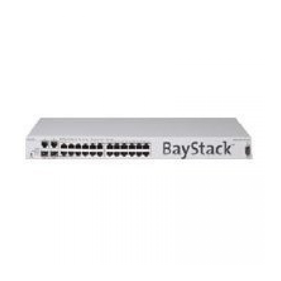
- Page 19 BayStack 425. Table 5 describes the components on the front panel. Figure 6 BayStack 425 front panel BayStack 425-24T Switch LED Status - Amber:10Mps Green:100 Mps Blink:Activity LED Status - Off:Half Duplex Green:Full Duplex Console...
-
Page 20: Checking Leds
Checking LEDs Refer to the illustration and tables that follow for descriptions of the LEDs on the BayStack 425 switch. The tables describe LED operation for a switch that has completed its power-on self-tests. Figure 7 shows the BayStack 425 switch LED display panel. Figure 7 BayStack 425 LED display panel Table 6 LEDs on the BayStack 425 Label... - Page 21 Label Color/Status Meaning Green Port 26 (BayStack 425-24T) or Port 50 (BayStack 425-48T) is currently enabled and the stacking port on the rear of the unit is inactive. GBIC/ Stack Port 26 (BayStack 425-24T) or Port 50 (BayStack 425-48T) is currently disabled and the stacking port on the rear of the unit is active.
-
Page 22: Initial Switch Setup
Table 8 SFP GBIC Port LEDs on the BayStack 425 (continued) Label Color/Status Meaning Green (blinking) There is activity on this port. A (Activity) There is no activity on this port. Initial switch setup The BayStack 425 switch begins switching as soon as you attach network devices and connect the switch to power. - Page 23 Connect the BayStack 425 switch to AC power. After the Nortel Networks banner is displayed, press [Ctrl ]-Y to display the Main Menu. At first the screen displays the Main Menu for a standalone switch. Then, if the switch is part of a stack configuration, the screen is refreshed when the stack forms to show the Main Menu for a stack configuration.
- Page 24 Figure 9 BayStack 425 Stack Mode Main Menu BayStack 425-48T Main Menu IP Configuration/Setup... SNMP Configuration... System Characteristics... Switch Configuration... Console/Comm Port Configuration... Identify Unit Numbers... Renumber Stack Units... Display Hardware Units... Spanning Tree Configuration... TELNET/SNMP/Web Access Configuration... Software Download... Configuration File...
- Page 25 Figure 10 IP Configuration/Setup screen IP Configuration/Setup BootP Request Mode: [ BootP Disabled Configurable In Use Last BootP ------------------ -------- ----------- In-Band Stack IP Address: [ 0.0.0.0 ] 0.0.0.0 0.0.0.0 In-Band Switch IP Address: [ 134.177.224.102 ] 134.177.224.102 0.0.0.0 In-Band Subnet Mask: [ 255.255.255.0 ] 255.255.255.0 0.0.0.0...
-
Page 26: Related Publications
In the In-Band Subnet Mask field, enter the IP subnet mask address. Note: If the In-Band Subnet Mask field does not already contain a value when you enter the IP address in the In-Band IP Address field, the switch software provides an in-use default value for the In-Band Subnet Mask field. - Page 27 Describes how to install the Java-based device level software management application. How to get help If you purchased a service contract for your Nortel Networks product from a distributor or authorized reseller, contact the technical support staff for that distributor or reseller for assistance.
- Page 28 (1-800-466-7835)to learn the telephone number for the nearest Technical Solutions Center. An Express Routing Code (ERC) is available for many Nortel Networks products and services. When you use an ERC, your call is routed to a technical support person who specializes in supporting that product or service. To locate an ERC for your product or service, go to the http://www.nortelnetworks.com/help/contact/...
- Page 29 Translations of the Safety Messages This section provides translations of the Caution, Danger, and Warning messages that appear within this document. Caution: This device is a Class A product. In a domestic environment, this device can cause radio interference, in which case the user may be required to take appropriate measures.
- Page 30 Warning: To avoid bodily injury from hazardous electrical shock and current, never remove the top cover of the device. There are no user-serviceable components inside. Warnung: Um gesundheitliche Schäden zu vermeiden, öffnen Sie nie den oberen Gehäusedeckel. Es befinden sich keine durch den Benutzer zu wartenden Teile im Inneren. Avertissement: pour éviter tout risque d ’électrocution, ne retirez jamais le couvercle du module.
- Page 31 Danger: Use only power cords that have a grounding path. Without a proper ground, a person who touches the switch is in danger of receiving an electrical shock. Lack of a grounding path to the switch may result in excessive emissions. Vorsicht: Verwenden Sie nur Netzkabel mit Schutzerdung.
- Page 32 Warning: Disconnecting the AC power cord is the only way to turn off AC power to this device. Always connect the AC power cord in a location that can be reached quickly and safely in case of an emergency. Warnung: Das Gerät kann nur durch Ziehen des Netzsteckers ausgeschaltet werden. Schließen Sie das Netzkabel an einer Steckdose an, die in Notfällen schnell und sicher zugänglich ist.
- Page 33 Warning: Fiber optic equipment can emit laser or infrared light that can injure your eyes. Never look into an optical fiber or connector port. Always assume that fiber optic cables are connected to a light source. Vorsicht: Glasfaserkomponenten können Laserlicht bzw. Infrarotlicht abstrahlen, wodurch Ihre Augen geschädigt werden können.
- Page 34 215658-B...
Need help?
Do you have a question about the BayStack 425-24T and is the answer not in the manual?
Questions and answers