Table of Contents
Advertisement
WARNING
Improper installation, adjustment, alteration, service or
maintenance can cause property damage, personal injury
or loss of life. Installation and service must be performed
by a licensed professional installer (or equivalent), service
agency or the gas supplier.
CAUTION
As with any mechanical equipment, personal injury can
result from contact with sharp sheet metal edges. Be
careful when you handle this equipment.
Table Of Contents
Shipping and Packing List ..............................................2
125/200 Unit Dimensions Single Fan .............................3
250/400 Unit Dimensions Dual Fan ................................4
Unit Parts Arrangement ..................................................5
Optional Accessory .........................................................6
Requirements in USA .....................................................6
Requirements in Canada ................................................6
Additional Requirements ................................................7
Unit Heater Installation ...................................................7
Combustion and Ventilation Air.....................................10
Venting..........................................................................10
Electrical Connections ..................................................15
Gas Connection ...........................................................19
Leak Check ..................................................................20
Be sure to read and understand the
structions in this manual.
ation, service or maintenance can cause
serious injury, death or property damage.
Do not store or use gasoline or other
cinity of this or any other appliance.
formed by a qualified installer, service
agency or the gas supplier.
RETAIN THESE INSTRUCTIONS FOR FUTURE REFERENCE
WARNING
FIRE OR EXPLOSION HAZARD.
Failure to
ly could result in serious injury, death,
or property damage.
WHAT TO DO IF YOU SMELL GAS:
Do not try to light any appliance.
Do not touch any electrical switch; do not use
any phone in your building.
Leave the building immediately.
Immediately call your gas supplier from a
neighbor's
structions.
If you cannot reach your gas supplier, call the
fire department.
INSTALLATION
INSTRUCTIONS
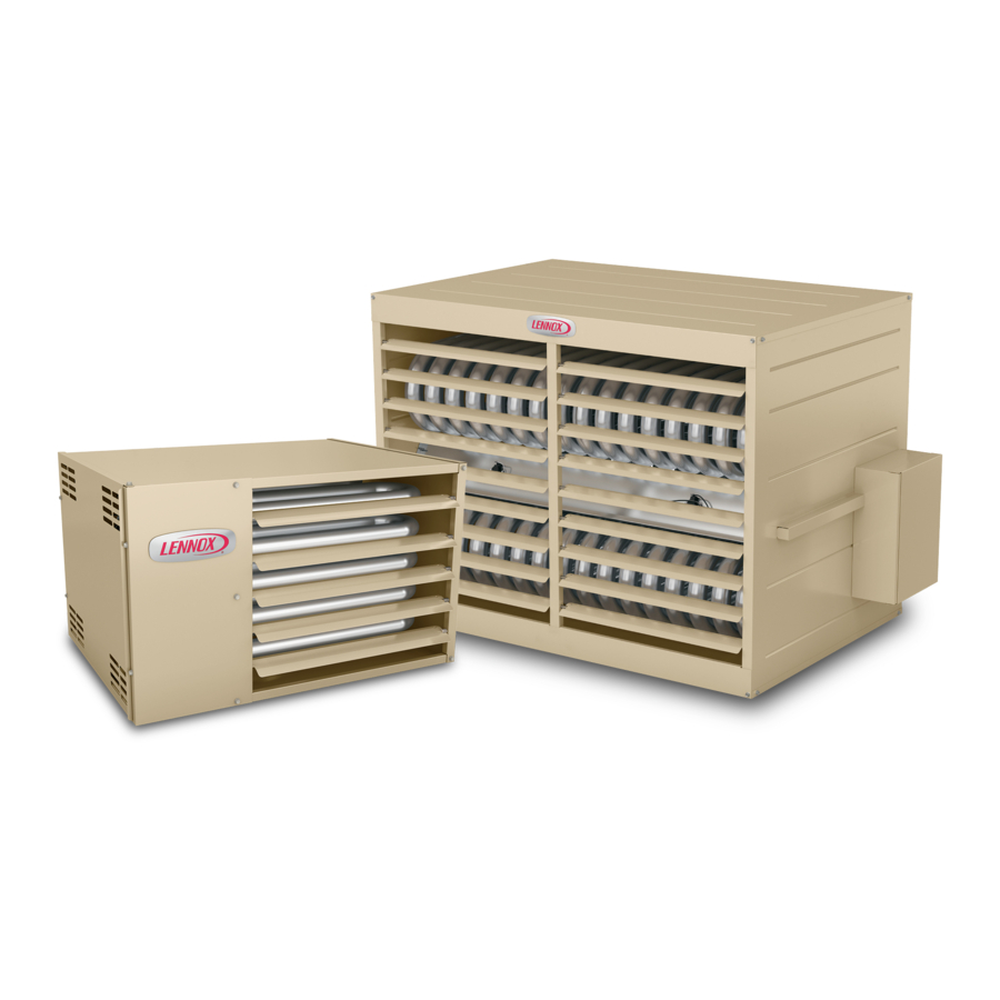
LS25
125,000 to 400,000 Btuh Series
SEPARATED COMBUSTION UNIT HEATERS
508064-01
1/2021
Replaces 10/2020
Note - Unit heaters are designed for indoor use only.
Unit Start-Up ................................................................20
To Turn Off Gas to Unit ................................................21
Heating Sequence of Operations ................................21
Ignition Control LED ....................................................22
High Altitude Adjustments ............................................22
Gas Flow .....................................................................22
Gas Pressure Adjustments ..........................................22
Limit Control Switch ......................................................23
Louver Vane Adjustment ..............................................23
Combustion Air Pressure Switch .................................23
Flame Roll-out Switch ..................................................23
Service..........................................................................23
Start-Up and Performance Checklist ...........................24
Page 1
Advertisement
Table of Contents

Subscribe to Our Youtube Channel
Related Manuals for Lennox LS25 Series


Summary of Contents for Lennox LS25 Series
-
Page 1: Table Of Contents
INSTALLATION WARNING INSTRUCTIONS Improper installation, adjustment, alteration, service or maintenance can cause property damage, personal injury LS25 or loss of life. Installation and service must be performed by a licensed professional installer (or equivalent), service agency or the gas supplier. 125,000 to 400,000 Btuh Series SEPARATED COMBUSTION UNIT HEATERS CAUTION... -
Page 2: Shipping And Packing List
Shipping and Packing List Package 1 of 1 contains: 1-Unit Heater 1-Combustion air box (shipped between combustion air blower and fan motors) 1-Rectangular to round flue transition - 5” diameter on 125-300 (provided and field-installed) - 6” diameter on 350-400 (provided and field-installed) Bag assembly containing: 1-Warranty card 1-Brand logo badge... -
Page 3: 125/200 Unit Dimensions Single Fan
10-1/2 16 (406) 5-3/8 10-3/4 (267) (137) (273) LS25-125-150-175-200 (SINGLE FAN) FLUE OUTLET 1/2 (13) 3 (76) COMBUSTION AIR INLET (TOP ORIENTATION) 3-1/8 (79) COMBUSTION 1/2 (13) (4) 3/8-16 MOUNTING NUTS AIR INLET FOR UNIT SUSPENSION 2-1/2 (64) (BOTTOM TOP VIEW ORIENTATION) ELECTRICAL INLETS 31-7/8... -
Page 4: 250/400 Unit Dimensions Dual Fan
16 (406) 10-1/2 5-3/8 10-3/4 (267) (273) (137) LS25-250-300-350-400 (DUAL FANS) FLUE OUTLET (13) (76) COMBUSTION AIR INLET (TOP ORIENTATION) COMBUSTION AIR INLET (BOTTOM ORIENTATION) 3-1/8 (79) 1/2 (13) (4) 3/8-16 MOUNTING NUTS 2-5/8 (67) FOR UNIT SUSPENSION TOP VIEW ELECTRICAL INLETS 14-1/8 31-7/8... -
Page 5: Unit Parts Arrangement
Page 5... -
Page 6: Optional Accessory
Optional Accessory Requirements in Canada These instructions are intended only as a general guide Units require a conversion kit when the unit is to be used and do not supersede local codes in any way. Authorities with LP/propane gas. The kit is ordered separately. See having jurisdiction should be consulted before installation. -
Page 7: Additional Requirements
TABLE 1 TABLE 2 UNIT CLEARANCES TO COMBUSTIBLE MATERIALS MAXIMUM MOUNTING HEIGHTS Side** Bottom Back Flue Unit Feet (Meters) Unit 125/150 16 (4.9) 125/400 175/200 20 (6.1) *6” is for single wall. Double wall B-vent clearance will be in accordance 250/400 30 (9.1) with the manufacturer’s listing. - Page 8 REMOVE AND DISCARD SHIPPING BRACKETS - IMPORTANT - REPLACE TWO SCREWS TWO COMBUSTION AIR ON EACH SIDE AFTER BOX BRACKETS DISCARDING THE (ONE ON EACH SIDE) COMBUSTION AIR BOX BRACKETS COMBUSTION AIR BOX FOUR SHIPPING BRACKETS (TWO ON EACH SIDE) COMBUSTION AIR BOX BRACKET (TWO ON 250-400 UNITS)
- Page 9 COMBUSTION AIR INTAKE FLANGE CONNECTOR (SHIPPED FACING THE INSIDE OF THE BOX; TURN DOWNWARD TO ACCEPT THE VENT PIPE AS SHOWN) FIGURE 4 Page 9...
-
Page 10: Combustion And Ventilation Air
Combustion and Ventilation Air Venting NOTE - The vent is a passageway, vertical or nearly so, Adequate facilities for supplying air for combustion and used to convey flue gases from an appliance, or its vent ventilation must be provided in accordance with the cur- connector, to the outside atmosphere. - Page 11 VERTICAL VENTS USING METAL VENT PIPE - 7 - Clearance to combustible material is 6” (152mm) COMMERCIAL AND RESIDENTIAL INSTALLATIONS for single-wall vent material except where a listed clearance thimble is used. Clearance to combustible These compact unit heaters are listed as Category 1 material for type B-1 vent or factory-built chimney is appliances for vertical vent installations.
- Page 12 HORIZONTAL VENTING 10 - Vent termination clearance to an unvented soffit or within 2 feet horizontally of a ventilated soffit must NOTE - Common venting is not allowed when horizontally be in accordance with local installation codes and venting the unit heater. the requirements of the gas supplier.
- Page 13 CONDENSATE DRAIN THROUGH TEE PIPE AND DRAIN LOOP UPWARD SLOPE ON HORIZONTAL VENT Category III adaptor must be 16 INCHES DRAIN installed before optional elbow (40.6cm) (if used). MIN. EXHAUST VENT TERMINATION NOTE - Minimum horizontal vent length is 3 ft. This does not 12 INCHES MIN.
- Page 14 CONDENSATE DRAIN THROUGH VENT TERMINATION DOWNWARD SLOPE ON HORIZONTAL VENT Category III adaptor must be 16 INCHES installed before optional elbow (40.6cm) (if used). MIN. EXHAUST VENT TERMINATION COMBUSTION AIR INLET TEE 12 INCHES MIN. LISTED WALL (30.5cm) BETWEEN AIR THIMBLE THROUGH INLET AND EXHAUST Venting may be single-wall (26 GSG)
-
Page 15: Electrical Connections
8 - If B-1 vent or an insulated flexible vent pipe cannot Electrical Connections be used as liners, the chimney must be rebuilt NOTE - Local codes may supersede any of the provisions to accommodate one of these methods or some outlined in this instruction. - Page 16 LINE VOLTAGE WIRING HIGH VOLTAGE WIRING 1 - Install a separate fused disconnect switch with the fuse sized according to the blower motor size. 125 / 400 NOTE - Electrically ground unit in accordance with local GRN-YEL codes or, in the absence of local codes, in accordance with the current editions of the ANSI/NFPA No.
- Page 17 5 3 8 0 2 5 -0 2 I GN CT RL HI GH VOL T AGE POW E R CONNE CT I ONS BL K W HT GRN- YE L W HT F I E L D PROVI DE D POW E R W I RI NG. CONNE CT T O P366 AND GRE E N GROUND S CRE W L OCAT E D I NS I DE UNI T .
- Page 18 5 3 8 0 2 4 -0 2 I GN CT RL HI GH VOL T AGE POW E R CONNE CT I ONS BL K W HT GRN- YE L BL U BL U W HT F I E L D PROVI DE D POW E R W I RI NG. CONNE CT T O P366 AND GRE E N GROUND S CRE W L OCAT E D I NS I DE UNI T .
-
Page 19: Gas Connection
Gas Connection GAS SUPPLY CONNECTION When connecting gas supply, the length of the run from the meter must be considered in determining the pipe size MANUAL to avoid excessive pressure drop. A line pressure of 7” MAIN SHUT-OFF VALVE (Furnished by Installer) w.g. -
Page 20: Leak Check
Return Air Temperature Requirements: Leak Check The following return air temperatures must be maintained for op- After gas piping is completed, carefully check all piping timum unit operation and extended life of the heat exchanger. connections, (field and factory), for gas leaks. Use a soap Failure to comply with the conditions will void the warranty. -
Page 21: To Turn Off Gas To Unit
To Turn Off Gas to Unit Heating Sequence of Operation 1 - When the thermostat calls for heat, the combustion 1 - Set thermostat to lowest level. air inducer starts immediately. 2 - Turn off all electrical power to unit if service is to be 2 - Combustion air pressure switch proves inducer performed. -
Page 22: Ignition Control Led
EHB for high altitude pressure switch kits. 4500 feet (1372m) above sea level is the jurisdiction of local authorities. Lennox recommends derating 4%/1000 The combustion air inducer proving switch is factory set. feet above 4,500 feet. Refer to table 7 for natural gas No adjustment is necessary. -
Page 23: Limit Control Switch
For White Rodgers 36H valve (Figure 12), supply pressure is Limit Control Switch accessed by removing 1/8” hex screw. Remove the 1/8” hex The limit control switch(es) is factory-set and is not screw and install a 1/8” fitting with hose barb. Connect tubing field-adjustable. -
Page 24: Start-Up And Performance Checklist
When ordering repair parts, include the complete unit model number listed on the unit rating plate. For exam- ple: LS25-125A-1. Contact the installing dealer, or visit www.lennox.com or call 1-800-9LENNOX for a list of the Lennox dealers in the area. Include manufacturer’s or distributor’s name and address. It is a requirement in the Z83.8 standard.
Need help?
Do you have a question about the LS25 Series and is the answer not in the manual?
Questions and answers