Table of Contents
Advertisement
Quick Links
Advertisement
Table of Contents

Related Manuals for OZGENC MAKINA OMRM 113

Summary of Contents for OZGENC MAKINA OMRM 113
- Page 1 Machine Operation Manual www.ozgencmachine.com...
-
Page 2: Table Of Contents
OMRM 113 User Manual Contents 1. DOCUMENT ISSUING INFORMATION ....................5 1.1 After-sales Service ......................... 5 1.2 Certification Process ........................6 1.3 Procedures to Follow ........................7 2. SCOPE OF USER'S GUIDE ........................8 3. Machine Description ........................... 9 3.1 Machine Specifications ........................ 10 3.2 General Machine Size ........................ - Page 3 OMRM 113 User Manual 9. Machine Installation .......................... 31 9.1. Machine Placement ........................33 9.2 Fixing on Ground ......................... 33 9.3 Start-up Preparation ........................33 9.4 Electrical Connections ......................... 33 9.5 Electrical Panel Scheme and Equipment Structure ..............34 9.6 Pneumatic Connections ....................... 36 10.
- Page 4 OMRM 113 User Manual 12. General Maintenance Issues ......................112 12.1 General Maintenance ......................112 12.2 Conditioner Water Level Control .................... 113 12.3 Cylinder Settings ........................114 12.4 Cylinder Sensor Settings ......................115 12.5 Setting the Conditioner ......................116 13. Warranty Disclaimer ........................117 13.1 Out of Warranty Situations .....................
-
Page 5: Document Issuing Information
OMRM 113 User Manual GENERAL INFORMATION Includes general topics related to the user's guide. 1. DOCUMENT ISSUING INFORMATION REVISION 2017 Özgenç Makina reserves the right to introduce technical changes. 1.1 After-sales Service Address: Nilüfer Organize Sanayi Bölgesi 113. Sk. No:23 Nilüfer... -
Page 6: Procedures To Follow
OMRM 113 User Manual 1.3 Procedures to Follow Warning symbols and phrases in this document should be taken into consideration. These warning signs are intended to protect occupational health and avoid any hazard. Beware of risk of burning your hands in case of contact. -
Page 7: Scope Of User's Guide
OMRM 113 User Manual 2. SCOPE OF USER'S GUIDE User’s guide is a document which must be read by the operating personnel before operating the machine. This guide covers all the required information for machine use. Information about how to provide long-term use of the machine and basic maintenance information is also contained in this document. -
Page 8: Machine Description
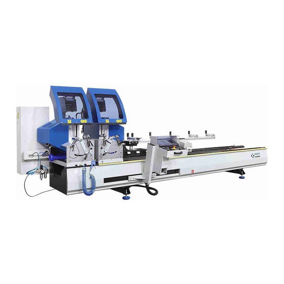
OMRM 113 User Manual 3. Machine Description Designed for cutting PVC and Aluminum profiles General Features: Performs double side precision cutting of PVC and Aluminum profiles in 45°- 90° angles and in angles within these ranges Machine provides automatic adjustment in 45°- 90° angles and easy adjustment in the angles within these ranges ... -
Page 9: Machine Specifications
OMRM 113 User Manual 3.1 Machine Specifications Operating Voltage Volt (V) Current Ampere (A) Used Force Kilowatt (Kw) Operating Pressure Used Force Lt / Min. Saw Details ØD1 Ød1 b1 (saw thickness) z (No. of teeth) Saw Rotating Angle (Automatic) Angle (°) -
Page 10: General Machine Size
OMRM 113 User Manual 3.2 General Machine Size Machine Length: 5164 mm Machine Width: 1564 mm Machine Height: 1567 mm 11 | P a g e... -
Page 11: Machine Cutting Capacity
OMRM 113 User Manual 3.3 Machine Cutting Capacity 12 | P a g e... -
Page 12: General Machine Structure
OMRM 113 User Manual 4. General Machine Structure Electrical Panel Profile Carrying Conveyors User Control Panel (Panel Pc ) “Optional” Barcode Printer "Optional" Protection Cover Saw Protection Cover 13 | P a g e... -
Page 13: General Structure Of Cutting Unit
OMRM 113 User Manual 4.1 General Structure of Cutting Unit Hydropneumatic Piston "Optional" Saw Movement Pistons Cutting Unit Movement Piston Profile Top Press System Short Profile Cutting Gauge Piston Clamp Cutting Unit Intermediary Angle Adjustment Handle Profile Side Press Piston Protection Sheet Cover Hydropneumatic Piston option;... -
Page 14: General Structure Of The Machine Body
OMRM 113 User Manual 4.2. General Structure of the Machine Body Movable Head Servo Motor Cable Conduit Sheet Toothed Rack 15 | P a g e... -
Page 15: Locations And Features Of Electrical Motors Used In The Machine
OMRM 113 User Manual 4.4 Locations and Features of Electrical Motors used in the Machine Motor Type Quantity Used Force Asynchronous 2,2 Kw Servo 0,4 Kw 17 | P a g e... -
Page 16: Features Of User Control Panel
OMRM 113 User Manual 4.5 Features of User Control Panel Brand: Weintek Model : cMT-iPC15 Display 15’’ (Touch) Dimension: Resolution: 1024x768 Memory: 32 GB and RTC Case: Aluminum Processor: Intel ATOM E3827 RAM : 4 GB 18 | P a g e... -
Page 17: Features Of Barcode Printer
OMRM 113 User Manual 4.5 Features of Barcode Printer Brand: Argox Model : OS-214 Plus Printing Method: Direct thermal (Printing without ribbon) Label type: Continuous form with center gap, Black Mark (separated with a black line) Label Outer Max. 109 mm... -
Page 18: Machine Layout
OMRM 113 User Manual 5. Machine Layout During machine installation, take the range of motion into account to operate the machine. Also, leave a suitable distance for the machine’s panel caps to open. Take following measures into account for safe operation. -
Page 19: Occupational Safety And Measures
Operator is responsible for use, cleaning, adjustment, operation, maintenance etc. 6.3 Machine Usage and Misuse OMRM 113 is designed for cutting PVC and Aluminum profiles Any machine fault and occupational safety gap other than those resulting from procedures are under user’s responsibility. -
Page 20: General Safety Rules
OMRM 113 User Manual 6.4 General Safety Rules OMR 113 Double Head Cutting machine is suitable for only one single operator. Operator must not operate the machine in case of any lack of attention caused by drugs, alcohol or medication. -
Page 21: Lighting Conditions
OMRM 113 User Manual 6.7 Lighting Conditions Operator must use the equipment with proper lighting conditions for his/her safety and health. Minimum lighting power must be 300 lux for machine use. For more technical information, please see EN 12464-1 Lighting Norm. -
Page 22: Safety Equipment
OMRM 113 User Manual 7. Safety Equipment DANGER! It is not permitted to remove or deactivate safety measures taken for the machine and equipment. -Location of EMERGENCY STOP on the machine! - Position of the Machine Main Switch 24 |... - Page 23 OMRM 113 User Manual -Double Manual Operation System It is required to push the buttons circled in red above located on two hands for the machine to move the saws (to start cutting). Protection covers that automatically close during cutting...
-
Page 24: Risky Areas And Warnings
OMRM 113 User Manual 7.1 Risky Areas and Warnings Safety measures are taken on the machine through equipment, but it is also required to comply with additional visual safety measures at the operating site. Any contact with moving parts may lead to electric shock. -
Page 25: Noise Emission
OMRM 113 User Manual 7.2 Noise Emission There is no noise emitted by machine units with an impact on occupational health. 7.3 Disposal of Hazardous Substances In case the user uses lubrication and cooling equipment, then apply the methods indicated on respective labels. -
Page 26: Machine Start-Up
OMRM 113 User Manual 8. Machine Start-up 8.1 Shipment Our machines are specially packed in accordance with the size and weight criteria. Main goal of packaging is to safely deliver the product free-of-damage to our customer. Some parts may be shipped as disassembled in line with the agreements with customer. - Page 27 OMRM 113 User Manual Movable Unit A) Movable Unit protection wedge. Movable unit is fixed during shipment for safety. 29 | P a g e...
- Page 28 OMRM 113 User Manual Control unit, covers of cutting units and conveyor are shipped as disassembled for overseas shipment. Cover for cutting unit Cover for cutting unit Conveyor Control Unit Screws of disassembled units are shipped as mounted in their places. Install the disassembled parts.
-
Page 29: Machine Placement
OMRM 113 User Manual 9.1. Machine Placement Use predefined hanger lifting points to position the machine at the site described in the plant layout. You may adopt the aforementioned methods of transport. Using any other method may damage your machine. -
Page 30: Electrical Panel Scheme And Equipment Structure
OMRM 113 User Manual 9.5 Electrical Panel Scheme and Equipment Structure This electrical panel scheme is presented solely for the purpose of placement of components within the panel. Please see ANNEXES for a detailed electrical diagram. Fuse Group Contactor Phase Protection Relay... - Page 31 OMRM 113 User Manual Equipment no "7" provided in electricity panel (Servo Motor Driver) is used to control servo motor. Servo motor is controlled by installing programming parameters in the driver (by downloading). Servo motors cannot be operated directly over the mains as asynchronous motors. Servo motor must be controlled by a servo driver system.
-
Page 32: Pneumatic Connections
OMRM 113 User Manual 9.6 Pneumatic Connections Attach the air house from the compressor to this inlet. Caution: Make sure that your air supply is dry! Solenoid Valve group controls the motion of current pneumatic equipment. Manual actions may also be performed by valves when necessary. - Page 33 OMRM 113 User Manual Valve Assembly Pneumatic Valve Valves and Their Functions Valve No. 1 Movable Unit Protection Cover Piston Movement Valve Valve No. 2 Movable Unit Saw Movement Piston Valve Valve No. 3 Fixed Unit Protection Cover Piston Movement Valve Valve No.
- Page 34 OMRM 113 User Manual Solenoid valves are electro-mechanical valves keeping the passage of air under control (direction control). Internal structure of solenoid valves; 1-) Valve body 2-) Inlet line 3-) Outlet line 4-) Solenoid/ Coil 5-) Winding Coil 6-) Cable Entry 7-) Piston 8-) Spring 9-) Orifice ...
-
Page 35: Machine Use
OMRM 113 User Manual 10. Machine Use 10.1 Machine Start/Stop Make sure that there are no foreign objects on machine prior to operation. 10.2 Turning on Machine Rotate the main switch clockwise until it slots into place. Main Switch: It completely cuts off the power supply from mains. - Page 36 OMRM 113 User Manual Control Unit is delivered after installing Windows operating system. Programs installed on the control unit for machines purchased with PC option ÖZGENC MACHINE CUTTING PROGRAM Team Viewer remote connection program (Used for remote maintenance by connecting the machine to internet) ...
- Page 37 OMRM 113 User Manual 10.3 Control List Button No. 1 Servo failure lamp. It is lit to inform the operator in case of servo failure. The button used to increase the movement speed of the movable unit. Press Button No. 2 button no.
- Page 38 OMRM 113 User Manual Press the button marked with a circle above to manually move the movable head left. Movable Unit If you require to move the machine left faster, press buttons marked with circles above at the same time.
- Page 39 OMRM 113 User Manual Press the button marked with a circle above to manually move the movable head right. Movable Unit If you require to move the machine right faster, press buttons marked with circles above at the same time.
- Page 40 OMRM 113 User Manual Press button marked with a circle above to activate presses on fixed and movable heads. Profile Side press Pistons Profile Top Press 44 | P a g e...
- Page 41 OMRM 113 User Manual Press button marked with a circle above to deactivate presses on fixed and movable heads. Profile Side press Pistons Profile Top Press 45 | P a g e...
- Page 42 OMRM 113 User Manual Green Button No. 1 Used to operate fixed unit saw motor Red Button No 1: Fixed unit is used to stop the operation of the saw motor Green Button No. 2 Used to operate movable unit saw motor...
- Page 43 OMRM 113 User Manual Press pistons are activated when profile is placed in the machine. Press buttons to operate saw motors. Saws will move forward to perform cutting after you press buttons marked with a circles above using both of your hands to perform cutting with saws.
- Page 44 OMRM 113 User Manual Any contact with moving parts may lead to electric shock. Do not use sharp objects on protective isolation equipment as they may do harm. Do not use pointed objects that can penetrate into the protective isolation equipment.
-
Page 45: Moving Equipment On Machine
OMRM 113 User Manual 10.4 Moving Equipment on Machine Movable control unit adjustable for the operator Movable cutting unit Cutting units that can be automatically tilted 90° and 45° 49 | P a g e... - Page 46 OMRM 113 User Manual Protection covers that automatically lower during cutting Saws Profile Press Pistons 50 | P a g e...
-
Page 47: Adjusting Profile Press Pistons According To The Profile
OMRM 113 User Manual 10.5 Adjusting Profile Press Pistons According to the Profile Fixing profile is highly important during cutting. Machine has two types of presses for this. ( “ 1-) Side press (standard), 2-) Top press (optional) “ ). Pressures must be adjusted according to profile type and shape. - Page 48 OMRM 113 User Manual Structure of Profile Side Press Piston Single Impact Cylinder Piston Shoe Adjusting profile press piston Piston Clamp Rotating Arm with Safety Catch Keep Rotating Arm with Safety Rotate piston clamp to align with Catch pulled in the direction of the profile the arrow as shown in the figure.
-
Page 49: Opening And Closing Top Press Pistons
OMRM 113 User Manual 10.5 Opening and Closing Top Press Pistons Top press rests can be operated or canceled as required Profile Upward Rest The valve must be aligned with the pipe to open top rest pressures. Move the valve in 90° with the pipe. -
Page 50: Tilting Cutting Units In Intermediary Angles
OMRM 113 User Manual 10.7 Tilting Cutting Units in Intermediary Angles Cutting units are automatically tilted to 45 and 90° with software support. If it is required to perform cutting in angles between 45 and 90°, cutting units must be manually adjusted. -
Page 51: Adjusting Saw Cutting Speeds
OMRM 113 User Manual 10.8 Adjusting Saw Cutting Speeds It is required to adjust saw cutting speed to cut profiles smoothly without burrs as well as increasing saw service life. The machine is equipped with hydropneumatic pistons to cut aluminum profiles stably. - Page 52 OMRM 113 User Manual Hydro-Pneumatic adjustment valves are used to adjust saw cutting speed. Hydro-Pneumatic Piston Adjustment Valve Turn adjustment valve left to increase cutting Turn adjustment valve right to decrease speed. cutting speed. 56 | P a g e...
-
Page 53: Saw Replacement
OMRM 113 User Manual 10.9 Saw Replacement Take necessary occupational safety measures before replacing a saw. Turn off the main switch. Turn off the machine's air inlet. Remove the protection cap of the saw unit. 32" wrench and 9" Allen set can be used for disassembly and installation. -
Page 54: Cooling Water Spray Valve Adjustment
OMRM 113 User Manual Move machine main switch to position "0" (closed) and cut air supply. Flang Scre Important Note: Check for saw deflection before working with the machine after saw replacement. 10.10 Cooling Water Spray Valve Adjustment Cooling water is used for smooth profile cutting and increasing saw life in machines with aluminum option. - Page 55 OMRM 113 User Manual Cooling Water Opening-Closing Valve Cooling Water Spray Valve Move Cooling Water Spray Valve to open Turn spray valve to increase cooling water position by moving it to pipe direction. spraying volume and decrease by turning it right.
- Page 56 OMRM 113 User Manual Filling cooling water in tanks; The machine has two cooling water tanks as one in fixed and one in movable unit. Cooling Water Tank Cooling Water Tank Cover Rotate and remove the red cover on the Fill one of the oils listed in the oil list below Cooling Water Tank.
-
Page 57: Lubricating Machine Rails
OMRM 113 User Manual Coolants that can be used in the Machine; Note: Mix the coolants to be used with the ratio stated on the label Po Bor Oil Houghton Dromus BA Eurolub TE 210 ES - Universal Bor Oil ... - Page 58 OMRM 113 User Manual Filling the Manual Lubrication Pump with Oil Oil Plug Remove the oil plug. Add one of the lubricants listed below until the container is full Lubricants that can be used in the machine: Festo Special Oil OFSW-32 ...
-
Page 59: Adding Lubricant To Conditioner
OMRM 113 User Manual 10.12 Adding Lubricant to Conditioner Air must be lubricated for pneumatic equipment to work continuously and quietly and have longer service life. Non-lubricated pneumatic piston felts get damaged and start working noisily, etc. Valves also create problems such as leakage due to contaminated air. - Page 60 OMRM 113 User Manual Filling conditioner with oil; Fill the glass container Press the black Remove metal Then rotate with one of the button on oil cover by and remove lubricants listed container and the glass pulling it down below and install the...
- Page 61 OMRM 113 User Manual This will switch to machine calibration page Language options menu This will switch to connection settings page Used to turn off the program and the computer You will see operation mode page after you select the language...
-
Page 62: Manual Cutting Mode
OMRM 113 User Manual Used to turn off the program and the computer Allows switching to manual cutting mode Allows switching to automatic cutting mode ( ERCOM Program is opened) Allows switching to long profile cutting mode Allows switching to wedge cutting mode Returns to previous menu (language options) 10.13.1 Manual Cutting Mode... - Page 63 OMRM 113 User Manual Used to enter company name on barcode paper Used to enter profile type on barcode paper Used to enter profile code on barcode paper Used for printing barcode after cutting Shows the distance that machine is located (in mm)
- Page 64 OMRM 113 User Manual Click the dimension field of target distance Write the desired dimension using the numeric panel in millimeter (mm) Important Note! Gauge must be used to cut pieces smaller than 500 mm. Gauge usage will be explained in the following sections.
- Page 65 OMRM 113 User Manual Movable cutting unit will move to target distance entered when "Start" command is clicked Adjusting Cutting Angles in Manual Mode ; 70 | P a g e...
-
Page 66: Cutting In Manual Cutting Mode
OMRM 113 User Manual Cutting angles are determined using buttons located under tabs called "Fixed Head" and "Movable Head" located in manual operation mode Note! Remember that movable and fixed cutting units are automatically moved only to 45 and 90°. - Page 67 OMRM 113 User Manual Then send the machine for calibration by pressing "HOME" button on the screen Select the preferred language in the language options menu Select Manual Cutting Mode using the operation mode screen 72 |...
- Page 68 OMRM 113 User Manual Click "Target Distance" in the next screen, enter the desired profile dimension using the numeric panel and press "ENT" (ENTER) Important Note! Gauge must be used to cut pieces smaller than 500 mm. Gauge usage will be explained in the following sections.
- Page 69 OMRM 113 User Manual Set the angles that you want to perform cutting Click "START" button and wait for the movable head to move to the dimension Place the profile in the machine Note! Do not forget to set the coolant spray if the profile to be cut is aluminum ...
- Page 70 OMRM 113 User Manual Buttons to Operate Saw Motor Perform cutting using cutting buttons NOTE ! You need to press cutting buttons with your both hands simultaneously to perform cutting 75 | P a g e...
-
Page 71: Cutting Short Pieces In Manual Cutting Mode
OMRM 113 User Manual Press "press rests deactive" button after cutting is complete and remove the cut profile 10.13.3 Cutting Short Pieces in Manual Cutting Mode A short piece cutting gauge is available on the machine for cutting pieces shorter than 500 mm. Short pieces can only be cut in "Manual Cutting Mode"... - Page 72 OMRM 113 User Manual Manually pull the button valve located on fixed head unit shown in the figure above towards yourself Short piece cutting gauge will move upwards Cutting Short Pieces; 77 | P a g e...
- Page 73 OMRM 113 User Manual Enter a dimension smaller than 500 mm and larger than 280 mm in manual cutting mode Press "START" and wait for the dimension called "RULER DISTANCE" to move to target dimension 78 | P a g e...
- Page 74 OMRM 113 User Manual Activate short piece cutting gauge Place the profile to be cut between gauge and movable head unit Press "press rests active" button on the control panel to fix the profile Press movable unit saw operation button...
-
Page 75: Printing Barcode In Manual Cutting Mode
OMRM 113 User Manual Perform profile cutting by pressing cutting buttons Press "press rests inactive" button and remove the cut profile when cutting is complete 10.13.4 Printing Barcode in Manual Cutting Mode Fill in the following fields and press "PRINT BARCODE" button to print barcodes in... - Page 76 OMRM 113 User Manual Screen keyboard will appear when you click Print Barcode button Screen Keyboard Used to print company name on barcode paper Used to print profile type on barcode paper Used to print profile code on barcode paper...
- Page 77 OMRM 113 User Manual Barcode paper will be printed according to information entered when you press Print Barcode 82 | P a g e...
-
Page 78: Cutting In Automatic Operation Mode
OMRM 113 User Manual 10.13.4 Cutting in Automatic Operation Mode Click "Automatic Cutting Mode" on operation mode screen Note! ERCOM program starts in Automatic Operation mode Note! ERCOM operation screen 83 | P a g e... -
Page 79: Automatic Operation Mode Screen
OMRM 113 User Manual Data files in .csv format are supported by the program. You can transfer a file in .csv format to control panel using "USB" (Universal Serial Bus), "local connection" or by creating yourself in ERCOM or similar programs. - Page 80 OMRM 113 User Manual Shows the number of profile to be cut Shows profile stock code Profile description (used to easily locate profiles) Shows order no. of profile(s) to be cut Shows the operation to be implemented on the profile (TES: Refers to Cutting with a...
- Page 81 OMRM 113 User Manual Used for program settings Shows the number of cut profiles Shows the percentage of ( % ) cut profiles in the cutting list Shows the number of profiles that are not cut Shows the percentage of ( % ) loaded cutting list Shows the status of communication with PLC Used to updated details (works as a “refresh”...
- Page 82 OMRM 113 User Manual Shows the length that the machine is located Shows the cutting angle of the fixed cutting unit Shows the cutting angle of the movable cutting unit NOTE ! When job order is load (file with CSV extension), optimization is applied to achieve the least scraps as possible.
-
Page 83: Loading New Order In Automatic Operation Mode
OMRM 113 User Manual 10.13.6 Loading New Order in Automatic Operation Mode Tabs will open at the top when you click "New Order" These tabs are; a. Add Profile b. Load Csv c. Transfer d. Exit Used to select profile manually and add to the list Used to locate the job order prepared using the program (.csv extension) in the... -
Page 84: Loading Cutting List Using Load Csv Command In Automatic Operation Mode
OMRM 113 User Manual Cutting list will be loaded to the program when transfer command is pressed. 10.13.7 Loading Cutting List Using Load CSV Command in Automatic Operation Mode Allows locating the cutting list from the usb device or directory that you previously loaded to... - Page 85 OMRM 113 User Manual Select the cutting list you want to load on the "Data Convertor" tab and press "Open" button Find the directory where cutting list is located and select the file with .csv extension This will load the cutting list to the program Sample .CSV Format...
- Page 86 OMRM 113 User Manual .CSV File Description ISNO Sent job order number. May be same as the file name (0001.CSV ISNO=0) PROFILNO Sequence no. ( 1…9999) POZNO Pos No ( 1…9999) MOUNTING 1=Top horizontal , 2=Right vertical, 3=Bottom horizontal, 4=Left vertical ISLEM 1=Water discharge, 2=Arm location, 3=Hinge, 4=D.O.
- Page 87 OMRM 113 User Manual with gasket, 13=Outer coating with gasket, 14= Double coating with gasket FIRMA Company Name MUSTERI Customer Name SEVKTAR Shipment Date PROFILBOYNO Height no. of optimized profiles SIPARISNO Order No SOLACI Left angle SAGACI Right angle PROFILADI...
-
Page 88: Profile Cutting In Automatic Operation Mode
OMRM 113 User Manual 10.13.7 Profile Cutting in Automatic Operation Mode Select "AUTOMATIC CUTTING" mode in Operation Mode menu Load the .csv file as described in section 10.13.7. Click Start. Load profile in the machine according to cutting list. - Page 89 OMRM 113 User Manual Press "press rests active" button on the control panel to fix the profile Activate saw motors Perform profile cutting by pressing cutting buttons Press "press rests inactive" button and remove the cut profile when cutting is complete...
-
Page 90: Profile Cutting In Long Cutting Mode
OMRM 113 User Manual Repeat the operations in this way NOTE ! Cutting units are automatically tilted according to cutting angle received from the program. 10.13.8 Profile Cutting in Long Cutting Mode Select "LONG CUTTING" mode in Operation Mode menu... - Page 91 OMRM 113 User Manual 96 | P a g e...
- Page 92 OMRM 113 User Manual Shows the current distance of the movable cutting unit Profile length to be cut between 4000 -7500 mm can be entered. (Dimensions can be entered using numeric keyboard opened after clicking target distance) Used to set saw cutting speed of fixed cutting unit...
-
Page 93: Profile Cutting In Wedge Cutting Mode
OMRM 113 User Manual Perform profile cutting by pressing cutting buttons Press "press rests inactive" button and remove the cut profile when cutting is complete 10.13.9 Profile Cutting in Wedge Cutting Mode Select "WEDGE CUTTING" mode in Operation Mode menu... - Page 94 OMRM 113 User Manual 99 | P a g e...
- Page 95 OMRM 113 User Manual Shows the current distance of the movable cutting unit Length of profile to be placed in the machine must be entered here Length of profiles to be cut must be entered here Counts the number of profiles to be cut...
-
Page 96: Calibrating The Machine
OMRM 113 User Manual Press "press rests inactive" button and remove the cut profile when cutting is complete NOTE ! Only fixed cutting unit works in wedge cutting mode. Movable unit drives the profile. 11. Calibrating the Machine ... - Page 97 OMRM 113 User Manual Then select “Manuel Mode” option Move cutting units to 90° 102 | P a g e...
- Page 98 OMRM 113 User Manual Enter target distance required to be cut Perform cutting Measure the cut profile Press buttons shown in picture below simultaneously 103 | P a g e...
- Page 99 OMRM 113 User Manual Click "Calibration Page" option seen on the screen Enter the dimension of the profile you have measured 104 | P a g e...
-
Page 100: Barcode Printer Settings And Operation Manual
OMRM 113 User Manual 11.1 Barcode Printer Settings and Operation Manual Please find "Turkish" user manual of Argox OS-214 Plus Barcode Printer in the link below: http://www.ekilavuz.com/kilavuz/ea8d94ed34a030f3/6/argox/os-214-plus/barkod-etiket-yazici Following is the video of "Installing Ribbon and Paper" operation for Argox OS-214 Plus Barcode Printer https://youtu.be/ALgXaIQEmM8... -
Page 101: Servo Alarm Codes And Meanings
OMRM 113 User Manual 11.2 Servo Alarm Codes and Meanings Protective function Name Cause Action Main Over-heat The temperature of the servo Improve the ambient temperature Protection drive heat sink and and cooling power devices has increased to conditions for the servo drive. - Page 102 OMRM 113 User Manual deceleration due to large load used for continuous inertia has regenerative braking. increased voltage at the Check the operation patterns converter, causing less (velocity monitor). regenerative resistor energy to Check the display for the indication be absorbed,...
- Page 103 OMRM 113 User Manual . Connect the shield to FG. Position Position deviation pulses have 1) Check if the motor rotates deviation exceeded the setup of according to the position excess Pr0.14 “Position deviation command pulse input. Check the protection excess setup”...
- Page 104 OMRM 113 User Manual frequency Pr5.32 “Command pulse error input maximum setup”. protection Command The scaling ratios used to set Check the setting values for the pulse the Command pulse command scaling. multiplier error counts per one motor protection revolution, the command...
- Page 105 OMRM 113 User Manual protection IF output Undefined numbers are used Correct the function assignment to function for the function assignment of the connector pins. number the output signals (SO1, SO2, error 1 and SO3). protection CL fitting error The deviation counter clear...
-
Page 106: General Maintenance Issues
OMRM 113 User Manual 12. General Maintenance Issues 12.1 General Maintenance DESCRIPTIONS DAILY WEEKLY MONTHLY Cleaning top and surroundings of machine Cleaning of oil and other wastes Cleaning of moving parts Cleaning of slides and threaded rods ... -
Page 107: Conditioner Water Level Control
OMRM 113 User Manual 12.2 Conditioner Water Level Control Reservoir Number 1 Conditioner Plug There must not be water in the glass tube on the left of the conditioner (container no. 1). Water must be discharged in case of accumulation. -
Page 108: Cylinder Settings
OMRM 113 User Manual 12.3 Cylinder Settings Loosen nut no. (1). Tighten or loosen bold no. (2). This helps to adjust the pressure on the piston (6) within the cylinder (5) and to determine the speed of the cylinder to drive the engine. Loosening the screw no. (3) can help to perform padding settings. -
Page 109: Cylinder Sensor Settings
OMRM 113 User Manual 12.4 Cylinder Sensor Settings Cylinder BACKWARD position sensor Cylinder FORWARD position sensor Sensor LED indicating light Note: In the normal standby position of the machine, backward and forward sensors of LED lights in relation to the cylinder position should be lit. You can adjust sensor settings using the special allen key located in the spare part box. -
Page 110: Setting The Conditioner
OMRM 113 User Manual 12.5 Setting the Conditioner For pressure settings: Pull up the regulator cap "1". Rotating clockwise will increase the outlet air pressure of the conditioner, while rotating counter-clockwise, will decrease the pressure. Discharging condensation fluid. Press or rotate the discharge screw "2"...
Need help?
Do you have a question about the OMRM 113 and is the answer not in the manual?
Questions and answers