Table of Contents
Advertisement
©2019 Lennox Industries Inc. Dallas, Texas, USA
THIS MANUAL MUST BE LEFT WITH THE OWNER
FOR FUTURE REFERENCE
These instructions are intended as a general guide and do
not supersede local codes in any way. Consult authorities
having jurisdiction before installation.
WARNING
Improper installation, adjustment, alteration, ser vice or
maintenance can cause property damage, personal
injury or loss of life.
Installation and service must be performed by a li censed
professional HVAC installer, service agency or the gas
supplier.
Failure to follow safety warnings and these instruc tions
exactly could result in property damage, dan gerous
operation, serious injury, or death.
Any additions, changes, or conversions required in order
for the appliance to satisfactorily meet the ap plication
needs must be made by a licensed profes sional HVAC
installer (or equivalent) using factory-specified parts.
Do not use this system if any part has been under water.
A flood-damaged appliance is extremely dan gerous.
Immediately call a licensed professional HVAC service
technician (or equivalent) to inspect the system and to
replace all controls and electrical parts that have been
wet, or to replace the system, if deemed necessary.
CAUTION
As with any mechanical equipment, contact with sharp
sheet metal edges can result in personal injury. Take
care while handling this equipment and wear gloves and
protective clothing.
To ensure proper system performance and reliability,
Lennox does not recommend operation of VRF systems
during any phase of construction. Construction debris,
low temperatures, harmful vapors, and operation of the
unit with misplaced filters can damage the units. Failure
to follow these guidelines will result in the warranty
being voided.
VRF
INSTALLATION
INSTRUCTION
VMDB Medium-Static Units
VRF SYSTEMS -- Indoor Units
507893-03
09/2019
The Clean Air Act of 1990 bans the intentional venting
of refrigerant (CFCs, HCFCs and HFCs) as of July 1,
1992. Approved methods of recovery, recycling or
reclaiming must be followed. Fines and/or incarceration
may be levied for noncompliance. These units must be
installed as a part of a matched system as specified in
the Product Specifications (EHB) bulletin.
General
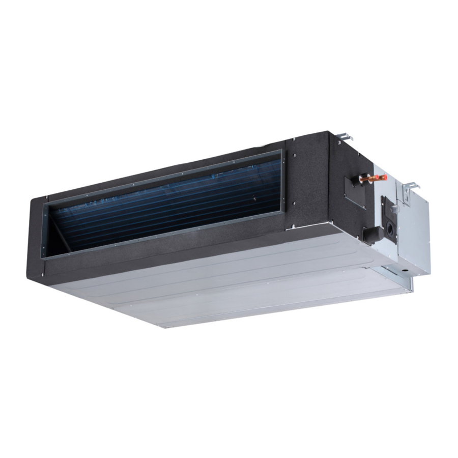
The VMDB medium-static ducted indoor units are matched
with an outdoor heat recovery or heat pump unit to create
a VRF (variable refrigerant flow) system that uses R-410A
refrigerant. VMDB indoor units are designed for indoor
installation only.
Refer to the Product Specification bulletin (EHB) for the
proper use of these indoor units with specific heat pumps,
heat recovery units, mode switching devices, branch
pipes, line sets and controls.
These instructions are intended as a general guide and
do not supersede local or national codes in any way.
Authorities having jurisdiction should be consulted before
installation.
Shipping and Packing List
Check the components for shipping damage. If you find
any damage, immediately contact the last carrier.
Package 1 of 1 contains the following:
1 - Assembled medium static, ducted unit
2 - Condensate drain insulation sleeves
1 - Flexible condensate connector
1 - Hose clamp
2 - Pipe reducers (VMD007, 009, 012 & 015)
1 - Resistor
1 - Cable
1 - Installation manual
1
IMPORTANT
Advertisement
Table of Contents

Related Manuals for Lennox VRF VMDB Series


Summary of Contents for Lennox VRF VMDB Series
- Page 1 1 - Hose clamp To ensure proper system performance and reliability, Lennox does not recommend operation of VRF systems 2 - Pipe reducers (VMD007, 009, 012 & 015) during any phase of construction. Construction debris, 1 - Resistor...
-
Page 2: Safety Requirements
NOTE - Only Lennox VRF indoor units will work with Lennox VRF outdoor units and associated mechanical equipment. Lennox Mini Split indoor units are similar in appearance but must not be connected to a Lennox VRF refrigerant circuit. Please refer to model numbers to confirm compatibility. Model numbers for Lennox VRF units start with a “V”... -
Page 3: Drain Connection
VMDB007-009 Unit Dimensions 1-3/4 (44) (19) SECTION A-A 2-3/4 1/2 (13) (70) (25) SUSPENSION BRACKETS (4) 13-3/4 13-3/4 (349) (359) 1-3/8 (35) 1-3/8 (35) 3/4(19) 3/4(19) 37-3/4 (959) TOP VIEW SECTION C-C CONDENSATE LIFT PUMP FRESH AIR SUSPENSION INTAKE 3-5/8 (92) BRACKETS (4) 19-7/8 (505) TOP OF UNIT... - Page 4 VMDB012-048 Unit Dimensions SECTION A-A SUSPENSION ELECTRICAL 1-3/4 (44) BRACKETS (4) CONTROL (25) 1-7/8 1/2 (13) (48) 1 (25) 1 (25) 3/4 (19) 3/4 (19) TOP VIEW SECTION C-C FRESH AIR INTAKE VMDB012 - 3-5/8 (92) Diameter VMDB015-048 - 5 (127) Diameter CONDENSATE LIFT PUMP SUSPENSION...
-
Page 5: Top View
Clearances Refer to Figure 1 for minimum clearance requirements. Wall 20” (508 mm) Minimum Service Clearance DUCTED UNIT Flow Minimum Service 24” (610 mm) Wall Clearance 24” (610 mm) Minimum Service Clearance TOP VIEW Ceiling 24” (610 mm) Minimum Clearance To ensure full fan deck removal a minimum distance of 24”... -
Page 6: Unit Placement
Unit Placement AVOID In addition to clearances, the following items should be Do not install the unit in the following locations: considered: • Areas exposed to petrochemicals or petrochemical products WARNING • Areas exposed to salt or other corrosive materials or Use the provided and specified components when caustic gasses installing equipment. - Page 7 Figure 4 to prevent transmission threaded rods. NOTE - Threaded rod (requirement of vibration from unit to structural ceiling. of Lennox warranty program) is the ONLY acceptable method of suspending the unit; do not use chains or ⅜” THREADED straps.
- Page 8 Return Air Filter Foldable Return Air Filter 2. Loosen the screw that secures the filter retaining bracket and slide the bracket away from the unit. The factory-supplied return air filter is hinged to allow it to be folded if needed to remove it from the unit in tight spaces.
- Page 9 Relocate Return Air Filter Instructions 5. Use the existing screws to re-install the return air filter frame on the bottom of the unit. See Figure 12. 1. Remove the return air filter from its existing location 6. Use the existing screws to re-install the return air at the rear of the unit.
-
Page 10: Refrigerant Piping Connections
Refrigerant Piping Connections WARNING IMPORTANT Refrigerant lines must be clean, dry, refrigerant-grade Refrigerant leaks are unlikely; however, if a refrigerant copper lines. Air handler coils should be installed leak occurs, open a door or windows to dilute the only with specified line sizes for approved system refrigerant in the room. -
Page 11: Sealing The Unit
• Field provided piping consists of two HVAC/R rated VMDB007-015 copper lines connected to the indoor unit. Use provided piping reducers. • Final equipment connections must be brazed Φ 3/4” connections. Compression or other types of fittings Φ 1/4” are not permitted for final connections. •... - Page 12 Condensate Piping Connections 4. See Figure 18 for applications including a single unit CAUTION using the internal drain pump. Make sure that drain piping is properly routed and insulated in order to prevent both leaks and condensation. IMPORTANT Follow these instructions exactly to ensure proper You must confirm operation of every drain and pump in drainage and unit operation.
- Page 13 8 in. 8 in. 8 in. 2~3-15/16 in. 2~3-15/16 in. 2~3-15/16 in. Indoor Unit INDIVIDUAL DRAIN OUTLET FROM EACH INDOOR UNIT MAIN DRAIN (Must be connected to internal pump and must be routed to (Sloped at 1/4” per foot (6 mm per 305 mm) AWAY main drain as shown.) from unit and should be supported as needed to prevent sagging.) Figure 19.
-
Page 14: Wiring Connections
Wiring Connections WARNING CAUTION Isolate the power supply before accessing unit electrical This unit must be properly grounded and protected by a terminals. circuit breaker. The ground wire for the unit must not be connected to a gas or water pipe, a lightning conductor Install unit so that unit disconnect is accessible. - Page 15 Indoor units and mode selection boxes on the same and maintenance purposes. Indoor unit and mode refrigeration circuit should have a common power selection box power supply MUST not be taken from the supply but must have an independent disconnect switch outdoor unit.
- Page 16 Outdoor unit Outdoor unit Outdoor unit (sub1 unit) (main unit) (sub2 unit) H1 H2 Outdoor Unit Communication Terminal Block (H1 H2 (H1 H2 (H1 H2 (PQ) (PQ) (PQ) (PQ) MS Box Communication Terminal Block HA HB 12V COM P (PQ) (PQ) Indoor Unit Communication Terminal Block Ground drain wire or...
- Page 17 Outdoor unit Outdoor unit Outdoor unit (main unit) (sub1 unit) (sub2 unit) (H1 H2 (H1 H2 (H1 H2 H1 H2 Outdoor Unit Communication Terminal Block (PQ) HA HB 12V COM P Indoor Unit Communication Terminal Block Ground cable shield (PQ) to Indoor Unit chassis Install a terminating resistor (Ω120) at the last indoor unit terminals P and Q of the daisy chain.
- Page 18 Title Code To wired Indoor fan motor controller comm. bus Room temperature sensor WHITE Inlet of evaporator sensor BLUE To wired NOTE: NOTE: Outlet of evaporator sensor controller 1. Refer to manual for communication Component in dash line is power Middle of evaporator sensor wiring optional or field wiring...
- Page 19 Relocate T1 Return Air Sensing 3. Cut the black wire between the plug and the sensor Relocate the unit return air sensing from inside the unit thermistor. Leave adequate room for making wiring to a location within the conditioned zone whenever the connections on each end.
- Page 20 Title Code To wired Indoor fan motor controller comm. bus Room temperature sensor WHITE Inlet of evaporator sensor BLUE To wired NOTE: NOTE: Outlet of evaporator sensor controller 1. Refer to manual for communication Component in dash line is power wiring Middle of evaporator sensor optional or field wiring...
- Page 21 Network Address and Commissioning After the system has been installed, each indoor unit must be assigned an address as part of the commissioning procedure. Spot Check Instructions Use the Spot Check Performance tables below and the Manual button on the unit receiver to view diagnostic information the indoor unit.
-
Page 22: Error Code Description
Troubleshooting Digital Display Make note of the code (E1, EE, etc.), then reset the display by pressing the ON/OFF button on the unit The indoor unit is equipped with a receiver that has a controller. Press the ON/OFF button a second time digital display that provides an error code. -
Page 24: Technical Support
Reference and adhere to the latest revision of the installation instructions. Installation instructions can be downloaded from www.lennoxvrf.com, www.lennoxcommercial.com, www.lennoxpros.com and the Lennox VRF and Mini-Splits app. Download the app from the Apple App Store or the Google Play store.