Table of Contents
Advertisement
©2018 Lennox Industries Inc. Dallas, Texas, USA
THIS MANUAL MUST BE LEFT WITH THE OWNER
FOR FUTURE REFERENCE
These instructions are intended as a general guide and do
not supersede local codes in any way. Consult authorities
having jurisdiction before installation.
WARNING
Improper installation, adjustment, alteration, ser vice or
maintenance can cause property damage, personal
injury or loss of life.
Installation and service must be performed by a li censed
professional HVAC installer, service agency or the gas
supplier.
Failure to follow safety warnings and these instruc tions
exactly could result in property damage, dan gerous
operation, serious injury, or death.
Any additions, changes, or conversions required in order
for the appliance to satisfactorily meet the ap plication
needs must be made by a licensed profes sional HVAC
installer (or equivalent) using factory-specified parts.
Do not use this system if any part has been under water.
A flood-damaged appliance is extremely dan gerous.
Immediately call a licensed professional HVAC service
technician (or equivalent) to inspect the system and to
replace all controls and electrical parts that have been
wet, or to replace the system, if deemed necessary.
CAUTION
As with any mechanical equipment, contact with sharp
sheet metal edges can result in personal injury. Take
care while handling this equipment and wear gloves and
protective clothing.
To ensure proper system performance and reliability,
Lennox does not recommend operation of VRF sys-
tems during any phase of construction. Construction
debris, low temperatures, harmful vapors, and opera-
tion of the unit with misplaced filters can damage the
units. Failure to follow these guidelines will result in the
warranty being voided.
VRF
INSTALLATION
INSTRUCTION
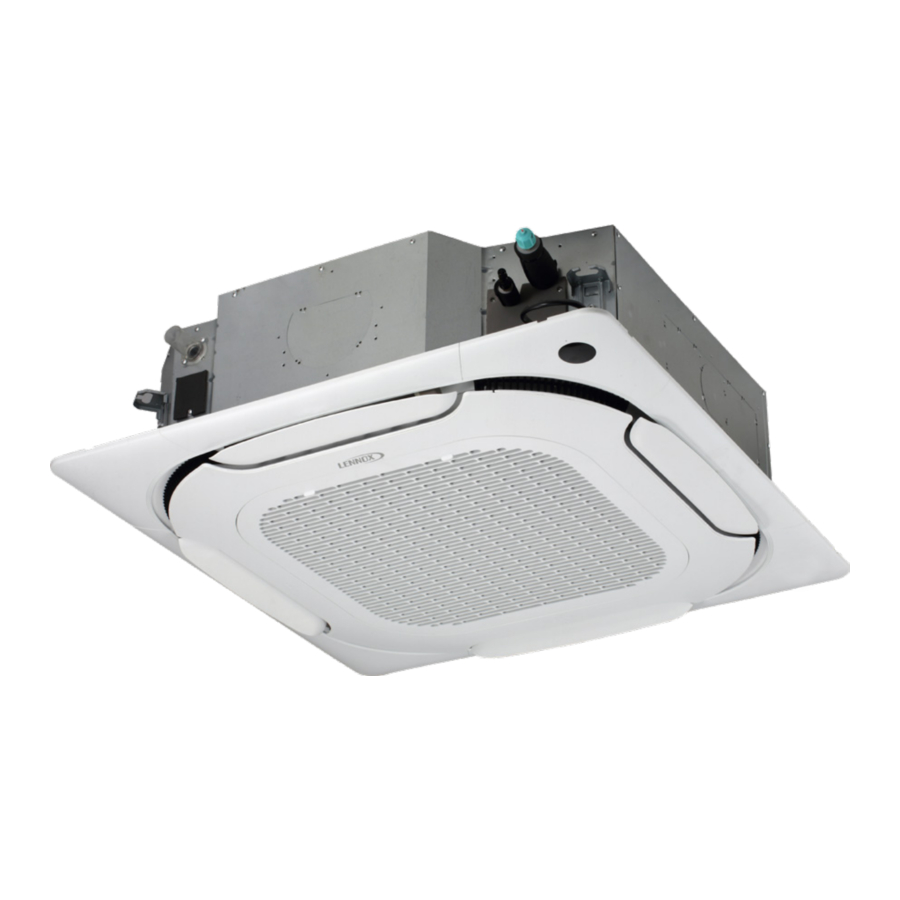
V33B 360º Cassette Units
VRF SYSTEMS -- Indoor Units
507890-02
01/2019
The Clean Air Act of 1990 bans the intentional venting
of refrigerant (CFCs, HCFCs and HFCs) as of July
1, 1992. Approved methods of recovery, recycling or
reclaiming must be followed. Fines and/or incarceration
may be levied for noncompliance. These units must be
installed as a part of a matched system as specified in
the Product Specifications (EHB) bulletin.
General
The V33B 360º cassette indoor units are matched with an
outdoor heat recovery or heat pump unit to create a VRF
(variable refrigerant flow) system that uses HFC-410A
refrigerant. V33B indoor units are designed for indoor
installation only.
Refer to the Product Specification bulletin (EHB) for the
proper use of these indoor units with specific heat pumps,
heat recovery units, mode switching devices, branch
pipes, line sets and controls.
These instructions are intended as a general guide and
do not supersede local or national codes in any way.
Authorities having jurisdiction should be consulted before
installation.
Shipping and Packing List
Check the components for shipping damage. If you find
any damage, immediately contact the last carrier.
Package 1 of 1 contains the following:
1 - Assembled indoor cassette unit base
8 - Nuts
8 - Washers
4 - Cover panel screws
5 - Wire ties
1 - Condensate drain flexible pipe
1 - Condensate drain insulation sleeve
1 - Clasp
1 - Cable
2 - Refrigerant pipe insulation
2 - Brass flare nuts
1 - Template
1 - Installation manual
NOTE - Assembled indoor unit cover panel is required for
complete installation and must be ordered separately.
1
IMPORTANT
Advertisement
Table of Contents

Related Manuals for Lennox VRF V33B Series


Summary of Contents for Lennox VRF V33B Series
- Page 1 1 - Cable protective clothing. 2 - Refrigerant pipe insulation To ensure proper system performance and reliability, Lennox does not recommend operation of VRF sys- 2 - Brass flare nuts tems during any phase of construction. Construction 1 - Template...
-
Page 2: Safety Requirements
NOTE - Only Lennox VRF indoor units will work with Lennox VRF outdoor units and associated mechanical equipment. Lennox Mini Split indoor units are similar in appearance but must not be connected to a Lennox VRF refrigerant circuit. Please refer to model numbers to confirm compatibility. Model numbers for Lennox VRF units start with a “V”... -
Page 3: Unit Dimensions - Inches (Mm)
Unit Dimensions - inches (mm) LIQUID 37-3/8 (949) 4-1/8 PIPE PIPE (105) DRAIN 30-3/4 (781) CONNECTION 1-1/4 (32) 4 (102) dia. SECONDARY SUPPLY DUCT CONNECTION 33-1/8 (841) 2-3/4 (70) dia. TOP VIEW BOTTOM VIEW FRESH AIR 6 (152) dia. INTAKE SECONDARY SUPPLY DUCT... - Page 4 Clearances (914) (914) (914) (914) Minimum Vertical Clearances: Minimum Clearance from Structural Ceiling to Drop Ceiling: 10-1/4 inches (260 mm) - 007, 009, 012, 015 models 13 inches (330 mm) - 015, 018, 024, 030, 036, 048 models Minimum Clearance to Floor: 90 inches (2286 mm) Maximum Clearance to Floor: 160 inches (4064 mm) Minimum Service Clearance for refrigerant and drain lines - 24 inches (610 mm) Typical cassette body shown, actual unit may vary.
- Page 5 Indoor Unit Placement WARNING AVOID Do not install the unit in the following locations: Do not install the unit in an area where flammable • Areas exposed to salt or other corrosive materials or materials are present due to risk of explosion resulting caustic gases in serious injury or death.
- Page 6 ⅜” threaded rods. associated flare nuts (See Figure 3), and to check the NOTE - Threaded rod (requirement of Lennox local disconnect. Ceiling framing should not restrict warranty program) is the ONLY acceptable method of access.
-
Page 7: Refrigerant Piping Connections
Refrigerant Piping Connections 8. After refrigerant piping has been installed and WARNING checked for leaks, apply insulation over all flared joints Refrigerant leaks are unlikely; however, if a refrigerant ensuring an air tight seal has been made between unit leak occurs, open a door or windows to dilute the connections and field supplied insulated piping. - Page 8 IMPORTANT! IMPORTANT Always use two wrenches when tightening flare Flared connections should always be accessible nuts to avoid twisting refrigerant piping. DO NOT and must be insulated to prevent condensation. over-tighten flare nuts. See Figure 5. INSULATE ALL FLARED CONNECTIONS Torque Wrench TO PREVENT CONDENSATION Backup...
- Page 9 6. After system installation is complete, the condensate Condensate Piping Connections drain line must be checked for leaks and the condensate pumps must be checked to ensure proper CAUTION operation. This check is part of the commissioning Make sure that drain piping is properly routed sequence.
-
Page 10: Wiring Connections
Wiring Connections WARNING CAUTION Isolate the power supply before accessing unit electrical This unit must be properly grounded and protected by a terminals. circuit breaker. The ground wire for the unit must not be connected to a gas or water pipe, a lightning conductor Install unit so that unit disconnect is accessible. - Page 11 Indoor units and mode selection boxes on the same Indoor unit and mode selection box power supply MUST refrigeration circuit should have a common power supply not be taken from the outdoor unit. Always follow NEC/ but must have an independent disconnect switch installed CEC and Local Codes.
- Page 12 Outdoor unit Outdoor unit Outdoor unit (sub1 unit) (main unit) (sub2 unit) H1 H2 Outdoor Unit Communication Terminal Block (H1 H2 (H1 H2 (H1 H2 (PQ) (PQ) (PQ) (PQ) MS Box Communication Terminal Block HA HB 12V COM P (PQ) (PQ) Indoor Unit Communication Terminal Block Ground cable shield...
- Page 13 Outdoor unit Outdoor unit Outdoor unit (main unit) (sub1 unit) (sub2 unit) (H1 H2 (H1 H2 (H1 H2 H1 H2 Outdoor Unit Communication Terminal Block (PQ) HA HB 12V COM P Indoor Unit Communication Terminal Block Ground cable shield (PQ) to Indoor Unit chassis Install a terminating resistor (Ω120) at the last indoor unit terminals P and Q of the daisy chain.
-
Page 14: Outside Air Connection
Supply Air Configurations Outside Air Connection A limited amount of filtered outside air can be brought into Supply air is typically provided from all four sides of the the cassette unit [through the 3 inch (76 mm)] outside air cassette unit. See Figure 15. knockout to be conditioned and mixed into the supply air. - Page 15 Figure 16. Three-way Outlet Possible Flow Patterns Typical cassette body shown, actual unit may vary. Figure 17. Two-way Outlet Possible Flow Patterns...
-
Page 16: Supply Duct
Installation of Secondary Supply Duct 1. Decide which side of the cassette body will be ducted. A limited amount of conditioned air can be diverted through a small duct to a location outside of the zone. For 2. Seal the supply air outlet on the side to which the duct example, a common application is for the cassette unit to will be attached. - Page 17 Cassette Cover Panel Installation NOTE - Cover panel must be ordered as a separate accessory. 1. Carefully remove the cassette cover panel from its CORNER ACCESS protective packaging and place the panel diffuser- COVER side-out on a clean, level surface. CAUTION Remove screws and loosen straps to remove corner...
- Page 18 8. Tighten the provided screws in the bracket in the CASSETTE BASE cover panel immediately below each panel hanger. HOOK REFRIGERANT HANGER See detail C in Figure 22. Adjust the cover panel by PIPING CONNECTIONS turning slightly clockwise, if necessary, to make sure CONDENSATE that the panel is properly aligned with the cassette DRAIN...
-
Page 19: Troubleshooting
Network Address and Commissioning After the system has been installed, each indoor unit must be assigned an address as part of the commissioning procedure. Spot Check Instructions Use the Spot Check Performance tables below and the Manual button on the unit receiver to view diagnostic information the indoor unit. -
Page 20: Error Code Description
Table 7. Fault Code Display on Indoor Unit Receiver Error Code Description No address Mode conflict Communication error between indoor and main outdoor unit T1 (Room temperature sensor) malfunction T2 (Middle of evaporator sensor) malfunction T2B (Outlet of evaporator sensor) malfunction T2A (Inlet of evaporator sensor) malfunction DC fan motor error EEPROM failure...
Need help?
Do you have a question about the VRF V33B Series and is the answer not in the manual?
Questions and answers