
Subscribe to Our Youtube Channel
Related Manuals for Micro Motion 2200S


Summary of Contents for Micro Motion 2200S
- Page 1 Configuration and Use Manual P/N MMI-20012741, Rev. A September 2008 ® Micro Motion Model 2200S Transmitters Configuration and Use Manual...
- Page 2 ©2008, Micro Motion, Inc. All rights reserved. ELITE and ProLink are registered trademarks, and MVD and MVD Direct Connect are trademarks of Micro Motion, Inc., Boulder, Colorado. Micro Motion is a registered trade name of Micro Motion, Inc., Boulder, Colorado. The Micro Motion and Emerson logos are trademarks and service marks of Emerson Electric Co. All other trademarks...
-
Page 3: Table Of Contents
Micro Motion customer service ........ - Page 4 Burst mode ..........69 ® Micro Motion Model 2200S Transmitters...
- Page 5 Micro Motion customer service ........
- Page 6 Configuration upload/download ........135 Connecting from a PC to a Model 2200S transmitter ..... . . 135 ProLink II language .
- Page 7 Connecting to a multidrop network ......141 Using the Communicator with the Model 2200S ......141 Communicator safety messages and notes .
- Page 8 ® Micro Motion Model 2200S Transmitters...
-
Page 9: Chapter 1 Before You Begin
This chapter provides an orientation to the use of this manual. This manual describes the procedures required to start, configure, use, maintain, and troubleshoot the Model 2200S transmitter. If you do not know what transmitter you have, see Section 1.4 for instructions on identifying the transmitter type from the model number on the transmitter’s tag. -
Page 10: Interpreting Your Model Number
Before You Begin Interpreting your model number Model 2200S transmitter options are encoded in the model number located on the transmitter tag. The model number is a string of the following form: 2200S*(H or K)******** In this string: • = No adapter-barrier supplied with the transmitter •... -
Page 11: Flowmeter Documentation
In other locations, phone +65 6777-8211 (Singapore) • In Europe: In the U.K., phone 0870 240 1978 (toll-free) In other locations, phone +31 (0) 318 495 555 (The Netherlands) Customers outside the U.S.A. can also email Micro Motion customer service at International.MMISupport@EmersonProcess.com. Configuration and Use Manual... - Page 12 ® Micro Motion Model 2200S Transmitters...
-
Page 13: Quick Start
Quick Start Overview This chapter provides “quick start” tools for people who already understand most or all of the commissioning methods and options for the Model 2200S transmitter. The following tools are provided: • Configuration overview and flowchart – see Section 2.2 •... - Page 14 Chapter 6 Liquid Define gas properties Configure the mA output Configure digital Configure density communications measurement Configure temperature Test and move to production measurement Chapter 7 Test Configure pressure compensation (optional) Backup Write-protect Done ® Micro Motion Model 2200S Transmitters...
-
Page 15: Configuration Worksheet
Quick Start Configuration worksheet The configuration worksheet in this section provides a place to specify and record information about your flowmeter and your transmitter configuration. If you are configuring multiple transmitters, make copies of this worksheet and fill one out for each transmitter. Configuration Worksheet Transmitter _______________________________ Transmitter model number... - Page 16 Enabled ______________________ Disabled Alarm menu Enabled Disabled Totalizer start/stop Enabled Disabled Totalizer reset Enabled Disabled Fault handling Status alarm severity _______________________________________________ _______________________________________________ _______________________________________________ _______________________________________________ _______________________________________________ _______________________________________________ _______________________________________________ LMV timeout Default (0 sec) Other ______________________________________ ® Micro Motion Model 2200S Transmitters...
- Page 17 Quick Start Configuration Worksheet Transmitter _______________________________ Sensor parameters Serial number ______________________________________________ Sensor material ______________________________________________ Liner material ______________________________________________ Flange ______________________________________________ Device parameters Descriptor ______________________________________________ Message ______________________________________________ Date ______________________________________________ Chapter 6 mA output Scale at DCS 12–20 mA (installation does not include adapter-barrier) 4–20 mA (installation includes adapter-barrier) Primary variable (PV) Mass flow...
-
Page 18: Menu Flowcharts
___ Live zero ___ Drive gain ___ GSV inventory Menu flowcharts This section provides the following menu flowcharts for the Model 2200S transmitter: • ProLink II menus Main menu – see Figure 2-2 Configuration menu – see Figures 2-3 and 2-4 •... -
Page 19: Prolink Ii Menus
Quick Start 2.4.1 ProLink II menus Figure 2-2 ProLink II main menu File View Connection ProLink Tools Plug-ins Load from Xmtr to File Connect to Device Commissioning Wizard Data Logging Save to Xmtr from File Connect to Fork Device Disconnect Options License ·... - Page 20 · Display ack all alarms set to Liquid Volume. · Burst cmd (2) Displayed only if Vol Flow Type is · Burst var 1-4 Offline password set to Standard Gas Volume. Auto scroll rate Update period ® Micro Motion Model 2200S Transmitters...
-
Page 21: Communicator Menus
Quick Start Figure 2-4 ProLink II configuration menu continued ProLink > Configuration Sensor T Series Special Units Sensor Simulation · Sensor s/n · FTG Base mass unit Enable simulation mode · Sensor model num · FFQ · Base mass time ·... - Page 22 TV is 2 PV LRV (4 mA or 12 mA) (1) Can also be configured from Detailed Setup menu. QV is (2) Can also be configured from Process Variables menu or HART Output menu. ® Micro Motion Model 2200S Transmitters...
- Page 23 Quick Start Figure 2-8 Communicator detailed setup menu On-Line Menu > 6 Detailed Setup Additional options Charize sensor Config fld dev vars Config outputs 1 Sensor type (read only) 1 Flow 1 Channel setup 2 Sensor selection 2 Density 2 HART output 3 Flow 3 Temperature 3 Modbus data...
- Page 24 · Revision #s 6 Display ACK All 7 Display offline password 8 Offline password 8/9 Update period (1) Displayed only if Display Offline Password is enabled. (2) Menu number varies depending on Display Offline Password configuration. ® Micro Motion Model 2200S Transmitters...
-
Page 25: Display Menus
Quick Start 2.4.3 Display menus Figure 2-10 Display menu – Managing totalizers and inventories Process variable display Scroll Mass total Scroll Volume total Select EXIT STOP/START RESET Scroll Scroll Scroll Select Select STOP/START YES? RESET YES? Select Scroll Select Scroll (1) The transmitter must be configured to allow resetting totalizers from the display. - Page 26 Quick Start Figure 2-12 Display menu – Maintenance – Version information Scroll and Select simultaneously for 4 seconds Scroll OFF-LINE MAINT Select Scroll Select Version info Scroll EXIT ® Micro Motion Model 2200S Transmitters...
- Page 27 Quick Start Figure 2-13 Display menu – Maintenance – Configuration: Units, AO, Meter Factors Scroll and Select simultaneously for 4 seconds Scroll OFF-LINE MAINT Select Scroll CONFG Select UNITS MTR F Additional options Scroll Scroll Select Select Select MASS MASS Scroll Scroll Scroll...
- Page 28 (3) If Offline Password is enabled, a Change Password screen is displayed immediately after DISPLAY ACK the Offline Password screen. Scroll AUTO SCRLL Scroll OFFLINE PASSW Scroll DISPLAY RATE Scroll DISPLAY LANG Scroll EXIT ® Micro Motion Model 2200S Transmitters...
- Page 29 Quick Start Figure 2-15 Display menu – Simulation (loop testing) Scroll and Select simultaneously for 4 seconds Scroll OFF-LINE MAINT Select Scroll Select SET MAO Select SET 12 mA Select (1) Fixes the output. (2) Unfixes the output....Select Scroll SET 16 mA...
- Page 30 Scroll Scroll Select Select ZERO/YES? Current zero display Scroll Select Scroll …………………. Factory zero display Scroll CAL FAIL CAL PASS RESTORE ZERO Troubleshoot Scroll Select Select RESTORE EXIT RESTORE ZERO/YES? Scroll Scroll Select Select ® Micro Motion Model 2200S Transmitters...
- Page 31 Quick Start Figure 2-17 Display menu – Alarms Scroll and Select simultaneously for 4 seconds SEE ALARM Select (1) This screen is displayed only if the ACK ALL ACK ALL function is enabled (see Section 5.2.4) and there are unacknowledged alarms. Select Scroll EXIT...
- Page 32 ® Micro Motion Model 2200S Transmitters...
-
Page 33: Getting Ready To Configure
Chapter 3 Getting Ready to Configure Overview This chapter contains information and procedures that are required or useful for flowmeter configuration planning and configuration. The following topics are discussed: • Applying power to the flowmeter – see Section 3.2 • Setting up and making an administrative connection –... -
Page 34: Setting Up And Making An Administrative Connection
Working with the mA output scale If the Micro Motion adapter-barrier is installed, the mA signal received by the host is scaled from 4–20 mA. If the adapter-barrier is not installed, the mA signal received by the host is scaled from 12–20 mA. -
Page 35: Converting Between Ma Output Scales
Figure 3-1 illustrates the mA measurement point options. As shown: • If your installation does not include the Micro Motion adapter-barrier, always use 12–20 mA. . • If your installation does include the Micro Motion adapter-barrier, be sure you know the... -
Page 36: Configuration Tips And Tricks
ProLink > Configuration > Device Restore Factory Configuration • Using the Communicator, select Diag/Service > Perform Diagnostic Action > Restore Factory Configuration All configuration parameters will be rewritten. Note: This action is not available from the display. ® Micro Motion Model 2200S Transmitters... -
Page 37: Display And Reporting Options For Process Variables
Display and reporting options for process variables Table 3-2 lists the process variables that are available from the Model 2200S, and how each of them can be displayed, reported, or queried. Refer to this list as you plan the transmitter configuration. - Page 38 ® Micro Motion Model 2200S Transmitters...
-
Page 39: Configuring Process Measurement
Chapter 4 Configuring Process Measurement Overview The process measurement parameters control how the transmitter interprets data from the sensor. Process measurement parameters include the following: • Characterization parameters – see Section 4.2 • General flow parameters – see Section 4.3 •... -
Page 40: Configuring General Flow Parameters
• Forward (positive) flow moves in the direction of the arrow on the sensor. • Reverse (negative) flow moves in the direction opposite of the arrow on the sensor. ® Micro Motion Model 2200S Transmitters... - Page 41 See Figure 4-1 if the LRV is set to 0 (zero flow). • See Figure 4-2 if the LRV is set to a negative value. In both figures, the mA output scale is 12–20 mA. If your installation includes the Micro Motion adapter-barrier, adjust the y axis as follows: •...
- Page 42 Under conditions of forward flow, if (the absolute value of) the flow rate equals or exceeds 100 g/s, the mA output will be proportional to the flow rate up to 20.5 mA, and will be level at 20.5 mA at higher flow rates. ® Micro Motion Model 2200S Transmitters...
- Page 43 Configuring Process Measurement Example 2 Configuration: • Flow direction = Reverse Only • mA output: LRV = 0 g/s; URV = 100 g/s (See the second graph in Figure 4-1.) As a result: • Under conditions of forward flow or zero flow, the mA output of the transmitter is 12 mA.
-
Page 44: Flow Damping
To configure flow damping: • Using the Communicator, select Detailed Setup > Config Fld Dev Var > Flow • Using ProLink II, click ProLink > Configuration > Flow Note: You cannot configure flow damping with the display. ® Micro Motion Model 2200S Transmitters... -
Page 45: Configuring Mass Flow Measurement
Configuring Process Measurement Configuring mass flow measurement The mass flow measurement parameters control how the flowmeter measures and reports mass flow. You must configure: • Mass flow measurement units • Mass flow cutoff Note: If you use the display, you can configure only the mass flow measurement unit. 4.4.1 Mass flow measurement unit The default mass flow measurement unit is g/s. -
Page 46: Mass Flow Cutoff
ConversionFactor -------------------------------------------- - y SpecialUnit(s) 5. Assign a name to the new special unit for mass flow. 6. Assign a name to the unit to be used for the associated mass totalizer and inventory. ® Micro Motion Model 2200S Transmitters... - Page 47 Configuring Process Measurement Example You want to measure the mass flow in ounces per second. 1. Set the base mass unit to pounds (lb). 2. Set the base time unit to seconds (sec). 3. Calculate and set the conversion factor: 16oz 0.0625 ----- -...
- Page 48 BBBL/D bbl/d Beer barrels/day Beer barrels per day SPECL Spcl special Special unit (see Section 4.6.2) (1) Unit based on oil barrels (42 U.S gallons). (2) Unit based on beer barrels (31 U.S gallons). ® Micro Motion Model 2200S Transmitters...
- Page 49 Configuring Process Measurement Table 4-5 Volume flow measurement units – Gas Volume flow unit Display Communicator ProLink II Unit description NM3/S Not available Nm3/sec Normal cubic meters per second NM3/MN Not available Nm3/min Normal cubic meters per minute NM3/H Not available Nm3/hr Normal cubic meters per hour NM3/D...
- Page 50 Detailed Setup > Config Fld Dev Var > Flow • Using ProLink II, click ProLink > Configuration > Flow Note: You cannot configure the volume flow cutoff or GSV flow cutoff with the display. ® Micro Motion Model 2200S Transmitters...
- Page 51 Configuring Process Measurement 4.6.2 Defining a special unit for volume or GSV flow To define a special unit for volume or GSV flow: 1. Navigate to the special units menu: • If you are using the Communicator, select Detailed Setup > Config Fld Dev Var > Flow > Spcl vol units •...
- Page 52 ProLink > Configuration > Density • Using the display, see Figure 2-13. 4.7.2 Density cutoff If the density measurement drops below the configured density cutoff, the transmitter will report a value of 0 for density. ® Micro Motion Model 2200S Transmitters...
- Page 53 Configuring Process Measurement Note the following: • The density cutoff is applied to the volume (liquid) measurement. If the density drops below its configured cutoff value, the volume flow rate will go to zero. • The density cutoff is not applied to the GSV measurement. The measured density values are used in GSV calculations.
- Page 54 Note: If you use the display, you can configure only the temperature measurement unit. 4.8.1 Temperature measurement units The default temperature measurement unit is °C. See Table 4-7 for a complete list of temperature measurement units. ® Micro Motion Model 2200S Transmitters...
- Page 55 Note: You cannot configure temperature damping with the display. Configuring pressure compensation The Model 2200S transmitter can compensate for the effect of pressure on the sensor flow tubes. Pressure effect is defined as the change in sensor flow and density sensitivity due to process pressure change away from calibration pressure.
- Page 56 1 Charize Sensor 2 Config field dev var 6 Pressure Comp 4 Pressure Enable pressure comp Enter Pressure unit Send Enter Flow factr Home Enter Dens factr Enter Flowcal pressure Enter Static Pressure Send Home Done ® Micro Motion Model 2200S Transmitters...
- Page 57 When you specify a new damping value, it is automatically rounded down to the nearest valid damping value. Valid damping values are listed in Table 4-8. Note: For gas applications, Micro Motion recommends a minimum flow damping value of 2.56. Before setting the damping values, review the following sections for information on how the damping values interact with other transmitter measurements and parameters.
- Page 58 Damping is also set to a non-zero value, the effect of damping the process variable is calculated first, and the added damping calculation is applied to the result of that calculation. See Section 6.2.4 for more information on the Added Damping parameter. ® Micro Motion Model 2200S Transmitters...
- Page 59 Chapter 5 Configuring Operational Parameters Overview The operational parameters control the behavior of the transmitter and flowmeter system. The following parameters can be configured: • Display parameters – see Section 5.2 • Fault handling parameters – see Section 5.3 In addition, this chapter provides information on sensor parameters (see Section 5.4) and device parameters (see Section 5.5).
- Page 60 To configure the display variables and display precision: • Using the Communicator, select Detailed Setup > Display Setup. • Using ProLink II, click ProLink > Configuration > Display • Using the display, see Figure 2-14. ® Micro Motion Model 2200S Transmitters...
- Page 61 Configuring Operational Parameters 5.2.4 Enabling and disabling display functions Table 5-2 lists the configurable display functions and describes their behavior when enabled (shown) or disabled (hidden). Do not enable display functions that require use of the display buttons if you do not want the operator to remove the transmitter housing cover.
- Page 62 • Flashes ALM_I if an alarm with severity level of Informational is active but no Fault alarm is active. • Takes no action for alarms with severity level of Ignore. • Operator has no access to detailed alarm information from the display. ® Micro Motion Model 2200S Transmitters...
- Page 63 • Using the display, see Figure 2-14. Configuring fault handling The Model 2200S transmitter performs self-diagnostics during operation. If the device detects certain events or conditions, the configured fault handling is implemented. Fault handling may include: • Performing the mA output fault action and the digital communications fault action, and showing alarm information on the display •...
- Page 64 Transmitter Initializing/Warming Up Fault Transmitter Initializing/Warming Up A010 Calibration Failure Fault Calibration Failure A011 Excess Calibration Correction, Zero too Low Fault Zero Too Low A012 Excess Calibration Correction, Zero too High Fault Zero Too High ® Micro Motion Model 2200S Transmitters...
- Page 65 Configuring Operational Parameters Table 5-5 Status alarms and severity levels continued Communicator message Default Affected by Alarm code ProLink II message severity Configurable LMV Timeout A013 Process too Noisy to Perform Auto Zero Fault Zero Too Noisy A014 Transmitter Failed Fault Transmitter Failed A016...
- Page 66 Configuration To configure sensor parameters: • Using the Communicator, select Detailed Setup > Device Information • Using ProLink II, click ProLink > Configuration > Sensor Note: You cannot configure sensor parameters with the display. ® Micro Motion Model 2200S Transmitters...
- Page 67 Configuring Operational Parameters Configuring device parameters The device parameters are used to describe the flowmeter as a system. Device parameters are listed and defined in Table 5-6. Note: The HART device ID, which is displayed in some menus, can be set only once, and is usually set at the factory to the device serial number.
- Page 68 ® Micro Motion Model 2200S Transmitters...
- Page 69 Chapter 6 Integrating the Meter with the Control System Overview This chapter discusses the following topics and tasks: • Configuring the mA output – see Section 6.2 • Configuring digital communications – see Section 6.3 Before beginning configuration, make an administrative connection to the transmitter and ensure that you are complying with all applicable safety requirements.
- Page 70 The upper range value (URV) – the value of the process variable that will be represented by a transmitter output of 20 mA Note: If the Micro Motion adapter-barrier is installed, the LRV will be represented by a transmitter output of 12 mA and an adapter-barrier output of 4 mA. The URV is not affected.
- Page 71 GSV flow. If a non-flow process variable has been assigned to the mA output, the AO Cutoff menu option is not available. Note: For most applications, the default AO cutoff is used. Contact Micro Motion customer support before changing the AO cutoff.
- Page 72 The Added Damping parameter specifies damping that will be applied to the mA output. It affects the measurement of the process variable assigned to the mA output. Note: For most applications, the default added damping value is used. Contact Micro Motion customer support before changing the Added Damping parameter.
- Page 73 Integrating the Meter with the Control System Example Configuration: • Flow Damping: 1 • mA output process variable: Mass flow • Added Damping: 2 As a result, a change in mass flow will be reflected in the mA output over a time period that is greater than 3 seconds. The exact time period is calculated by the transmitter according to internal algorithms which are not configurable.
- Page 74 • Software Tag (HART tag) • Loop Current Mode • Burst Mode • PV, SV, TV, and QV assignments Note: See Section 3.3 for information on setting the HART address and the software tag. ® Micro Motion Model 2200S Transmitters...
- Page 75 If the Loop Current Mode parameter is disabled, the mA output from the transmitter is fixed at 12 mA and therefore cannot be used to report process data. If the Micro Motion adapter-barrier is installed, the mA output will appear to be fixed at 4 mA.
- Page 76 The SV, TV, and QV are not reported through an output. They can be queried via digital communications or reported via burst mode. Table 6-7 lists the valid assignments for the PV, SV, TV, and QV on the Model 2200S transmitter. Table 6-6...
- Page 77 Integrating the Meter with the Control System Table 6-6 Process variable assignments for PV, SV, TV, and QV continued Process variable ✓ ✓ ✓ Gas standard volume inventory ✓ ✓ ✓ Gas standard volume total ✓ ✓ ✓ LPO amplitude ✓...
- Page 78 The transmitter sends four process variables in each burst. See Step 4. (1) If the Micro Motion adapter-barrier is installed, the mA value will be converted to the 4–20 mA output scale at the adapter-barrier. ™ (2) This burst mode setting is typically used with the HART Tri-Loop signal converter.
- Page 79 Chapter 7 Testing and Moving to Production Overview This chapter contains information and procedures that may be useful for testing the flowmeter before moving it into production. The following topics are discussed: • Zeroing the flowmeter – see Section 7.2 •...
- Page 80 7.2.2 Performing the zero procedure To zero the flowmeter: • Using the display, see Figure 7-1. • Using the Communicator, see Figure 7-2. • Using ProLink II, see Figure 7-3. ® Micro Motion Model 2200S Transmitters...
- Page 81 Testing and Moving to Production Figure 7-1 Display – Flowmeter zero procedure Scroll and Select simultaneously for 4 seconds Scroll OFF-LINE MAINT Select Note: For a complete presentation of Scroll the Zero menu structure, see Figure 2-16. ZERO Select ZERO/YES? Select ………………….
- Page 82 ProLink > Calibration > Zero Calibration Modify zero time if required Perform Auto Zero Calibration in Progress LED turns red Wait until Calibration in Progress LED turns green Calibration Green Failure LED Done Troubleshoot ® Micro Motion Model 2200S Transmitters...
- Page 83 Testing and Moving to Production Loop testing A loop test is a means to: • Verify that the mA output is being sent by the transmitter and received accurately by the receiving devices • Determine whether or not you need to trim the mA output Note the following: •...
- Page 84 SET 12 mA Select Correct at Troubleshoot receiving device? Select Scroll SET 16 mA Select Correct at Troubleshoot receiving device? Select Scroll SET 20 mA Select Correct at Troubleshoot receiving device? Select Scroll EXIT ® Micro Motion Model 2200S Transmitters...
- Page 85 Testing and Moving to Production Figure 7-5 Communicator – Loop test procedure On-Line Menu > 3 Diag/Service > 2 Loop test Set mA measurement point 1 Fix Analog Out 1 4 mA 20 mA Other Correct? Loop test successful Check output wiring END to unfix Troubleshoot receiving device Configuration and Use Manual...
- Page 86 12 mA signal. Note: If a barrier or the Micro Motion adapter-barrier is installed, the mA output trim procedure can be extended to include additional trimming and calibration. See Section 7.4.2.
- Page 87 • Any trimming performed on the output should not exceed ± 200 microamps. If more trimming is required, contact Micro Motion customer support. • If you are using the Communicator, the receiving device value can contain up to two decimal places.
- Page 88 Enter receiving device Enter receiving device value in Enter Meas value in Enter Meas Next Next Read mA output at Read mA output at receiving device receiving device Equal? Equal? Next Back Back Finish ® Micro Motion Model 2200S Transmitters...
- Page 89 Adapt the following procedure as required for your installation: 1. Trim the mA output at the Model 2200S transmitter as described in Section 7.4.1. Use a milliamp measurement point between the Model 2200S transmitter and the I.S. barrier or the Micro Motion adapter-barrier (i.e., mA Measurement Point = 12–20 mA).
- Page 90 3. Specify the name and location of the backup file. To restore the configuration dataset: 1. Connect to the transmitter using ProLink II. 2. Select File > Send to Xmtr from File 3. Specify the name and location of the backup file. ® Micro Motion Model 2200S Transmitters...
- Page 91 Testing and Moving to Production Write-protecting the configuration To prevent unintended changes to the transmitter configuration, you can write-protect the configuration. To write-protect the configuration using ProLink II: 1. Click ProLink > Configuration > Device 2. Enable write-protection. To write-protect the configuration using the Communicator: 1.
- Page 92 ® Micro Motion Model 2200S Transmitters...
- Page 93 Chapter 8 Operating the Transmitter Overview This chapter describes how to use the transmitter in everyday operation. The following topics and procedures are discussed: • Interpreting mA output data – see Section 8.3 • Recording process variables – see Section 8.4 •...
- Page 94 Operating the Transmitter Recording process variables Micro Motion suggests that you make a record of the process variables listed below, under normal operating conditions. This will help you recognize when the process variables are unusually high or low, and may help in fine-tuning transmitter configuration.
- Page 95 Operating the Transmitter 8.5.2 With ProLink II To view process variables with ProLink II: 1. The window opens automatically when you first connect to the transmitter. Process Variables 2. If you have closed the window: Process Variables a. Open the menu.
- Page 96 If no Fault or Informational alarm is active, the display flashes the term at the end NO ALARM of the display variables. Note: Unacknowledged alarms are not listed at the end of the display variables. ® Micro Motion Model 2200S Transmitters...
- Page 97 Operating the Transmitter To view or acknowledge status alarms using the display menus, see the menu flowchart in Figure 2-17. Note that the Acknowledge All Alarms display function may be enabled or disabled. If disabled, the Acknowledge All Alarms screen is not displayed and alarms must be acknowledged individually.
- Page 98 Note: The timestamp value is not reset during a transmitter power cycle. To reset this value, you must perform a master reset or use a Modbus command. Contact Micro Motion customer support. To view records in the alarm event log, select Diag/Service >...
- Page 99 Operating the Transmitter 1. To view totalizer values, wait or until the process variable appears and the units Scroll TOTAL of measure are: • For the mass totalizer, mass units (e.g., kg, lb) • For the volume totalizer, volume units (e.g., gal, cuft, scf, nm3) See Figure 8-1.
- Page 100 RESET • Select ( alternates with RESET • Select (volume totalizer resets). • Scroll to EXIT • Select. (1) This feature may be enabled or disabled. See Section 5.2.4. ® Micro Motion Model 2200S Transmitters...
- Page 101 Operating the Transmitter With ProLink II Table 8-3 shows how you can control the totalizers and inventories using ProLink II. Table 8-3 Totalizer and inventory control with ProLink II To accomplish this On the totalizer control screen... Stop all totalizers and inventories Click Stop Start all totalizers and inventories...
- Page 102 ® Micro Motion Model 2200S Transmitters...
- Page 103 Before performing the procedures in this chapter, make an administrative connection to the transmitter and ensure that you are complying with all applicable safety requirements. Meter validation and calibration The Model 2200S transmitter supports the following procedures for the evaluation and adjustment of measurement performance: •...
- Page 104 Note: For density or temperature calibration to be useful, the external measurements must be accurate. Micro Motion flowmeters with the Model 2200S transmitter are calibrated at the factory, and normally do not need to be calibrated in the field. Calibrate the flowmeter only if you must do so to meet regulatory requirements.
- Page 105 ExternalStandard 3. Ensure that the meter factor is between , inclusive. If the calculated meter factor is outside these limits, contact Micro Motion customer service. 4. Configure the meter factor in the transmitter. To configure meter factors: • Using ProLink II, see Figure 2-3.
- Page 106 D1 and D2 density calibration require a D1 (low-density) fluid and a D2 (high-density) fluid. You may use air and water. 9.4.2 Density calibration procedures To perform a D1 and D2 density calibration: • With the Communicator, see Figure 9-1. • With ProLink II, see Figure 9-2. ® Micro Motion Model 2200S Transmitters...
- Page 107 Measurement Performance Figure 9-1 D1 and D2 density calibration – Communicator D1 calibration D2 calibration Close shutoff valve Fill sensor with D1 fluid Fill sensor with D2 fluid downstream from sensor 3 Diag/Service > On-Line Menu > 3 Calibration > 3 Diag/Service >...
- Page 108 Enter density of D2 fluid Do Cal Do Cal Calibration in Progress Calibration in Progress light turns red light turns red Calibration in Progress Calibration in Progress light turns green light turns green Close Close Done ® Micro Motion Model 2200S Transmitters...
- Page 109 Measurement Performance Performing temperature calibration Temperature calibration is a two-part procedure: temperature offset calibration and temperature slope calibration. The entire procedure must be completed without interruption. Note: Before performing the calibration, record your current calibration parameters. You can do this by saving the current configuration to a file on the PC.
- Page 110 ® Micro Motion Model 2200S Transmitters...
- Page 111 Chapter 10 Troubleshooting 10.1 Overview This chapter describes guidelines and procedures for troubleshooting the flowmeter. The information in this chapter will enable you to: • Categorize the problem • Determine whether you are able to correct the problem • Take corrective measures (if possible) •...
- Page 112 If the transmitter does not operate at all (i.e., the transmitter is not receiving power and cannot communicate), perform all of the procedures in Section 10.14. If the procedures do not indicate a problem with the electrical connections, contact the Micro Motion customer service department.
- Page 113 Troubleshooting 10.7 Low power and mA fault action If the A031 (low power) alarm appears and disappears frequently, check the mA Fault Action setting and the power supply to the transmitter. If the transmitter is operating near the limit of its power requirement, and mA Fault Action is set to Upscale, the mA output will be set to a high value when the alarm occurs, and the extra power may be enough to correct the problem temporarily.
- Page 114 • Check the LRV and URV. See Section 10.18. mA reading correct at low mA loop resistance may be too high • Verify mA output load resistance is below currents but wrong at higher maximum supported load (see installation currents transmitter manual). ® Micro Motion Model 2200S Transmitters...
- Page 115 Cause Suggested remedy A001 EEprom Checksum An uncorrectable • Cycle power to the flowmeter. Error (Core checksum mismatch has • The flowmeter might need service. Contact Micro Motion. Processor) been detected. (E)EPROM Checksum Error (CP) A002 RAM Test Error ROM checksum error or a •...
- Page 116 A014 Transmitter Failed Many possible causes. • Cycle power to the flowmeter. • The transmitter might need service. Contact Micro Motion. Transmitter Failed A016 Line RTD The value computed for • Check the sensor RTD circuitry. See Section 10.24.
- Page 117 K1 values. See Section 4.2. Type K1 value indicates a • Check the sensor RTD circuitry. See Section 10.24. curved tube, or vice versa. • If the problem persists, contact Micro Motion. Incorrect Sensor Type (K1) A029 Internal Transmitter electronics •...
- Page 118 Simulation Mode Active 10.13 Checking process variables Micro Motion suggests that you make a record of the process variables listed below, under normal operating conditions. This will help you recognize when the process variables are unusually high or low. •...
- Page 119 Troubleshooting Table 10-4 Process variables problems and remedies continued Symptom Cause Suggested remedy Erratic non-zero flow rate under Leaking valve or seal • Check pipeline. no-flow conditions Slug flow • See Section 10.17. Plugged flow tube • Check drive gain and tube frequency. Purge the flow tubes.
- Page 120 Incorrect K2 value • Verify characterization. See Section 4.2. Unusually high tube frequency Sensor erosion • Contact Micro Motion. Unusually low tube frequency Plugged flow tube, corrosion, or erosion • Purge the flow tubes. Unusually low pickoff voltages Several possible causes •...
- Page 121 1. Verify that the loop wires are connected as shown in the wiring diagrams in the transmitter installation manual. 2. If a barrier or the Micro Motion adapter-barrier is installed: • Ensure that the active/passive power configuration of the barrier matches the wiring. If external power is being used, verify the power supply to the barrier.
- Page 122 Check the wiring between the transmitter and the receiving device, including all wiring at the I.S. barrier or Micro Motion adapter-barrier (if applicable). • If an I.S. barrier or Micro Motion adapter-barrier is installed, test the signal between the transmitter and the barrier, then between the barrier and the receiving device. •...
- Page 123 Troubleshooting 10.18 Checking output saturation If an output variable exceeds the upper range limit or goes below the lower range limit, the transmitter produces an output saturation alarm. The alarm can mean: • The process is outside normal operational limits. •...
- Page 124 Micro Motion calibrates every transmitter at the factory. Therefore, you should suspect improper calibration only if the transmitter has been calibrated after it was shipped from the factory. Before performing a calibration, consider meter validation or meter verification and select the appropriate procedure (see Section 9.2).
- Page 125 Incorrect sensor type configured • Verify sensor type configuration, then verify sensor characterization. See Section 4.2. Open drive or left pickoff sensor coil • Contact Micro Motion. Drive board or module failure, cracked flow tube, • Contact Micro Motion. or sensor imbalance 10.23.3...
- Page 126 Note: To check the sensor circuitry, you must remove the transmitter from the sensor. Before performing this test, ensure that all other applicable diagnostics have been performed. Diagnostic capabilities of the Model 2200S transmitter have been greatly enhanced, and may provide more useful information than these tests.
- Page 127 The readings across pin pairs should be steady. • Actual resistance values depend on the sensor model and date of manufacture. Contact Micro Motion for more detailed data. If a problem appears, or if any resistance is out of range, contact Micro Motion. Configuration and Use Manual...
- Page 128 • F300 sensors RTD – and fixed resistor • All other sensors RTD – and LLC (1) Actual resistance values depend on the sensor model and date of manufacture. Contact Micro Motion for more detailed data. Figure 10-2 Feedthrough pins Drive + Drive –...
- Page 129 With the DMM set to its highest range, there should be infinite resistance on each lead. If there is any resistance at all, there is a short to case or a short between pins. See Table 10-8 for possible causes and solutions. If the problem is not resolved, contact Micro Motion. Table 10-8...
- Page 130 ® Micro Motion Model 2200S Transmitters...
- Page 131 0.0 – 60.0 sec User-entered value is corrected to nearest lower value in list of preset values. For gas applications, Micro Motion recommends a minimum value of 2.56. Mass flow units Mass flow cutoff 0.0 g/s Recommended setting is 5% of the sensor’s rated...
- Page 132 Base volume time Volume flow conversion factor 1.00000 Base GSV time Base GSV unit GSV conversion factor 1.00000 Variable Primary variable Mass flow mapping Secondary variable Density Tertiary variable Mass flow Quaternary variable Volume flow ® Micro Motion Model 2200S Transmitters...
- Page 133 Default Values and Ranges Table A-1 Transmitter default values and ranges continued Type Setting Default Range Comments mA output Primary variable Mass flow –200.00000 g/s Automatically reset when primary variable is reset. 200.00000 g/s Automatically reset when primary variable is reset. AO cutoff 0.00000 g/s AO added damping...
- Page 134 ® Micro Motion Model 2200S Transmitters...
- Page 135 For detailed information on installation and wiring procedures, see the transmitter installation manual. Transmitter components The Model 2200S transmitter can be either integral-mount or extended-mount. • Figure B-1 shows an exploded view of the Model 2200S transmitter and its components, integral-mount. • Figure B-2 shows the extended-mount option.
- Page 136 Flowmeter Installation Types and Components Figure B-2 Model 2200S transmitter – Extended-mount Conduit openings Transmitter housing cover Sensor case Sensor case Clamping ring Terminal diagrams Figure B-3 shows the transmitter’s wiring terminals. These terminals are used for both power supply and I/O.
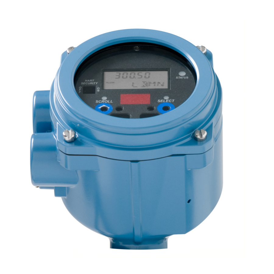
- Page 137 Codes and abbreviations used by the display – see Section C.5 Identifying the components of the user interface The user interface of the Model 2200S transmitter is shown in Figure C-1. The transmitter housing cover has been removed. Figure C-1...
- Page 138 Model 2200S Display and User Interface The user interface components have the following functions: • Display – displays process data • buttons – used to navigate the display and the display menu system Scroll Select • HART clips – used to make a HART administrative connection to the transmitter, typically...
- Page 139 Model 2200S Display and User Interface C.4.2 Entering floating-point values from the display menus Certain configuration values, such as meter factors or output ranges, are entered as floating-point values. When you first enter the configuration screen, the value is displayed in decimal notation (as shown in Figure C-2) and the active digit is flashing.
- Page 140 Model 2200S Display and User Interface To change from decimal to exponential notation (see Figure C-3): until the rightmost digit is flashing. Select , then . The display changes to provide two spaces for entering the exponent. Scroll Select 3. To enter the exponent: until the desired digit is flashing.
- Page 141 Model 2200S Display and User Interface Codes and abbreviations Table C-1 lists and defines the codes and abbreviations that are used for display variables. Table C-2 lists and defines the codes and abbreviations that are used in the off-line menu.
- Page 142 Model 2200S Display and User Interface Table C-2 Codes used in off-line menu continued Code or abbreviation Definition Comment or reference Select ENABL Enable to enable EXTRN External FAC Z Factory zero Flow calibration factor FLDIR Flow direction FLSWT, FL SW...
- Page 143 ProLink II, see the ProLink II manual. The manual is available on the Micro Motion web site (www.micromotion.com). Menu flowcharts for using ProLink II with the Model 2200S transmitter are provided in Figures 2-2 through 2-4.
- Page 144 You may connect directly to the mA/HART terminals (terminals 1 and 2) if you have removed the user interface module. Figure D-1 HART/Bell 202 connections to network See Step 3 DCS or mA output wiring See Step 3 Connection is polarity-insensitive See Step 3 ® Micro Motion Model 2200S Transmitters...
- Page 145 Connecting with ProLink II Software Figure D-2 HART/Bell 202 connections to HART clips Connection is polarity-insensitive Note: Additional resistance may be required. See Step 3. 3. Add resistance as required. The HART signal converter must be connected across a resistance of 250–600 Ω.
- Page 146 Note: Other languages may be available, depending on the version of ProLink II. To configure the ProLink II language, use the Tools menu. See Figure 2-2. In this manual, English is used as the ProLink II language. ® Micro Motion Model 2200S Transmitters...
- Page 147 Use the alpha keys to type information If you are unable to perform the tasks listed above, consult the Communicator manual before attempting to use the software. The documentation is available on the Micro Motion web site (www.micromotion.com). Communicator device description device description must be installed on the Communicator.
- Page 148 3. The Communicator must be connected across a resistance of 250–600 Ω. Add resistance to the connection. See Figure E-1. Figure E-1 Connecting to HART clips HART clips Connection is Communicator polarity-insensitive 250–600 Ω resistance ® Micro Motion Model 2200S Transmitters...
- Page 149 All Communicator procedures assume that you are starting at the on-line menu. “Online” appears on the top line of the Communicator main menu when the Communicator is at the on-line menu. Menu flowcharts for using the Communicator with the Model 2200S transmitter are provided in Figures 2-5 through 2-9.
- Page 150 ® Micro Motion Model 2200S Transmitters...
- Page 151 Index Numerics totalizers and inventories 12–20 mA output resetting 93 See mA output, scale starting and stopping 93 4–20 mA output viewing values 91 See mA output, scale Configuration backing up and restoring 82 burst mode 69 Added damping 64 characterizing 31 Administrative connection 26 damping...
- Page 152 Configuration files resetting totalizers 92 upload and download 135 stopping and starting 92 Connecting to the transmitter viewing values 90 with ProLink II 135 update period 51 with the Communicator 140 using 130 ® Micro Motion Model 2200S Transmitters...
- Page 153 Index Display parameters 51 Documentation additional documentation 3 troubleshooting 106 manual organization 1 Inventories Drive gain, troubleshooting 116 definition 90 resetting 92 stopping and starting 92 Engineering unit viewing values 90 See Measurement unit Language Factory configuration 28 used by ProLink II 138 Factory zero 71 used on display 51 Fault action...
- Page 154 Meter factors 95 viewing values 91 configuration 97 version 2, 114 Meter validation 95 procedure 97 See Primary variable Micro Motion customer service 3, 104 Model number 2 Quaternary variable 68 Off-line password See Quaternary variable enabling/disabling 53 setting 53...
- Page 155 Index Testing loop test 75 Unit sensor simulation 82 density 44 Totalizers GSV flow 39 definition 90 mass flow 37 enabing/disabling resetting from display 53 See also Special unit enabling/disabling starting and stopping from temperature measurement 46 display 53 volume flow 39 resetting 92 Update period stopping and starting 92...
- Page 156 ® Micro Motion Model 2200S Transmitters...
- Page 158 © 2008, Micro Motion, Inc. All rights reserved. P/N MMI-20012741, Rev. A *MMI-20012741* For the latest Micro Motion product specifications, view the PRODUCTS section of our web site at www.micromotion.com Micro Motion Inc. USA Worldwide Headquarters 7070 Winchester Circle Boulder, Colorado 80301...
Need help?
Do you have a question about the 2200S and is the answer not in the manual?
Questions and answers