Advertisement
Quick Links
APFSC
SMART CONTROL WIFI MODULE USER GUIDE
The APFSC Smart Control Wi-Fi module can be wired to a Force 10 / Force 48 intruder panel. The APFSC will
send alarm notifications via the building Wi-Fi to your Android™ or iOS® App.
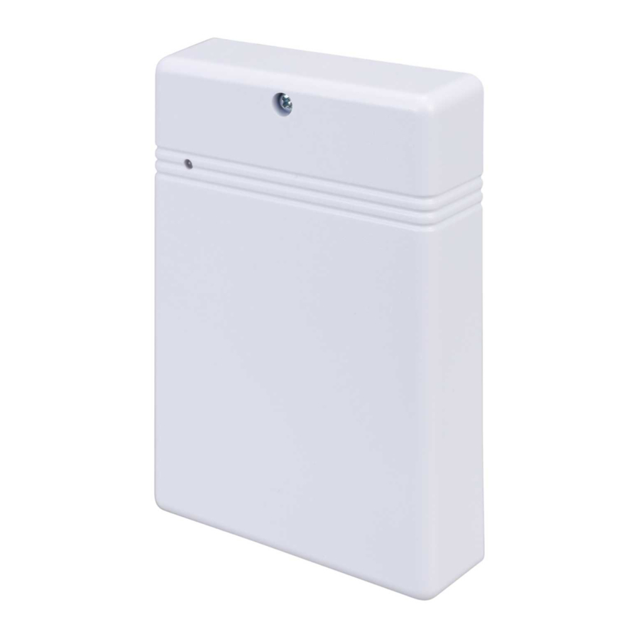
1: Dual colour LED
Green Power
Red Data
2: Cover Screw
3: Learn Switch
Challenger_APFSC_Instructions_Rev01
Advertisement

Related Manuals for Challenger APFSC


Summary of Contents for Challenger APFSC
- Page 1 SMART CONTROL WIFI MODULE USER GUIDE The APFSC Smart Control Wi-Fi module can be wired to a Force 10 / Force 48 intruder panel. The APFSC will send alarm notifications via the building Wi-Fi to your Android™ or iOS® App.
- Page 2 Wiring diagram to Force10 Wiring diagram to Force10 with Integral Communicator Outputs Note: When PIR or N.C. is not connected then the J7 jumper link should be moved to the left side. When using PIR or NC, the J7 jumper link should be on the right side and Force10 in Full set Mode. This port is not valid on disarm.
-
Page 3: Important Note
(an additional separate PSU may be required). • If you have a power cut or the power is lost to your router/Wi-Fi unit then the APFSC will be unable to forward any notifications to your mobile device/App. Communication will also need to be active to your internet provider. - Page 4 Smartphones/Tablets with Dialer is defined as Main User. Then the “Main User” can share the QR code with other Smartphones/Tablets for creating “Sub User”. Each APFSC dialer can bind up to 1 “Main user” and “10 Sub users”.
- Page 5 Ensure the dialer, mobile and router with a good signal (within 3 meters), Please note that 5Ghz channel routing is not supported. Then, connect the mobile device to the same Wi-Fi you want the APFSC to be connected too, (please ensure "Guest" networks are selected) perform the following steps;...
- Page 6 ⚫ Enter the Wi-Fi password ○ ⚫ Then, press and hold the [Program button] of the APFSC Dialer for 6 seconds. The Red LED will flash that the Dialer is now under connecting mode ⚫ Click the “Start airlink” button on the App to start the connection process (please be patient).
- Page 7 Functions Check Device Status All registered Dialer(s) is displayed on "Device List" page ⑦. When you click one of the items, it will enter the corresponding operation interface of the device ○ ,and shows the current status of ○ each device either at Arm or Disarm with icon (i.e. The Arm icon as ),The current status of each terminal is shown on the right○...
- Page 8 ○ ⚫ Device Name ○ ⚫ Device Icon ○ ⚫ Push Notification ○ ⚫ Change disarm password ○ ⚫ Endpoint name ○ Once finished, click [Save] to store the setting *** Main User and Sub User have different privilege for the setting, Gray display indicates that the current user does not have right to set *** Change Device Name and Icon The Dialer can be named according to user preference (i.e.
- Page 9 Check alarm event Alarm event including arm, disarm and endpoint alarm ○ Both Main and Sub user can check the alarm event. Click the “Event” to check the latest 60 alarm events as below: 4.09 Manage Sub User Only Main user can manage Sub user, include add and delete user; Click the “Management” ○ 1 5 , the menu will be displayed as ○...
-
Page 10: Specifications
5. Specifications Power Supply: DC 9~14V Work Current Trigger 200mA Max Stand-by Current 30mA Transmission range: 20 meters (open air with direct line of sight) Transmission frequency: 2.4G Wi-Fi 802.11 b/g/n supported Smartphones/Tablets: iOS® and Android™ only System Requirement: iOS® 8.0, Android™6.0 or above. Challenger_APFSC_Instructions_Rev01... - Page 11 Due to our policy of continuous improvement we reserve the right to change specification without prior notice. Errors and omissions excepted. These instructions have been carefully checked prior to publication. However, no responsibility can be accepted by Challenger Security Products for any misinterpretation of these instructions. CHALLENGER SECURITY PRODUCTS 10 Sandersons Way Blackpool, FY4 4NB Email: enquiries@challenger.co.uk...
Need help?
Do you have a question about the APFSC and is the answer not in the manual?
Questions and answers