
Related Manuals for Marvelmind Super-NIA-3D


Summary of Contents for Marvelmind Super-NIA-3D
- Page 1 Marvelmind Indoor Navigation System Operating manual v2020_12_14 www.marvelmind.com...
-
Page 2: Table Of Contents
Mini-TX beacon .........................37 Beacon Industrial-TX-Metal ....................38 Beacon Industrial-RX ......................40 Industrial Super-Beacon Metal-25kHz ................42 Beacon HW v4.9........................43 4.1. Starter Set Super-NIA-3D ...................... 44 4.2. Starter Set HW v4.9 ....................... 52 4.3. Starter Set NIA-01-3D......................61 4.4. Starter Set NIA-SmallDrone ....................70 4.5. - Page 3 5.1. Starter Set Super-MP-3D ....................... 98 5.2. Starter Set IA-01-2D ......................107 5.3. Starter Set IA-02-3D ......................116 6.1. Dashboard general view ...................... 125 6.2. Diagnostics messages window .................... 126 6.3. Table of distances ....................... 127 6.4. Devices list .......................... 129 6.5.
- Page 4 System Accuracy Evaluation ....................233 9.10. Calibration of the accelerometer ..................234 9.11. Settings to obtain correct north direction ................236 9.12. Communication of Pixhawk with Marvelmind mobile beacon ..........237 9.13. Sending path to robot ......................238 9.14. Proper ultrasonic coverage ....................242 9.15.
- Page 5 Version changes V2020_12_14 FCC notice for Modem HW v5.1 description added Minor fixes and improvements V2020_12_04 Starting up chapters improved Minor fixes and improvements V2020_12_01 Starting up chapters improved Submap’s settings chapter improved SW update chapter improved with DFU Programming descriptions Minor fixes and improvements V2020_11_24 Licenses chapter updated...
- Page 6 Super-Modem SW update described Minor fixes and improvements V2020_04_09 Minor fixes and improvements V2020_04_07 Background color described Height input in Starting up chapters described Minor fixes and improvements V2020_02_27 Geofencing zones described IMU axis positioning for Super-Beacon described External microphones soldering scheme for Super-Beacon improved V2020_02_21 Minor fixes and improvements V2020_02_14...
- Page 7 Stationary beacons’ colors described Minor fixes and improvements V2019_06_13 Delay tuning described Update rate tuning described Minor fixes and improvements V2019_06_07 F.A.Q. and Troubleshooting improved Architectures comparison improved Receiving and transmitting angles illustrations added (v4.9 chapter and Mini-RX chapter) Ceiling and mirroring buttons described V2019_06_03 TDMA described V2019_05_28...
- Page 8 Major new feature – support for 250 beacons (mobile + stationary combined) and 250 submaps per modem New feature: user must setup handover zones between submaps to guarantee handover quality for complex maps with multi-floor and similar New feature: default wireless connection is setting is now 153kbps (used to be 38kbps). Radio profile 153kbps provides radio coverage range nearly as much as 38kbps and update rate nearly as high 500kbps, i.e.
- Page 9 Executive summary Marvelmind Indoor Navigation System is an off-the-shelf indoor navigation system, designed to provide precise (±2cm) location data to autonomous robots, vehicles (AGV), and copters. It can also be used to track moving objects via mobile beacons attached to them. Other applications include, for example, forklifts, virtual reality (VR) systems, helmets for construction workers or miners, etc.
-
Page 10: Key Capabilities
1.1. Key capabilities: Parameter Technical Specifications Reaches up to 50 meters in lab conditions (Mini-RX or Super-Beacon to HW v4.9 with RX4 Distance between only) beacons Recommended distance is 30 meters (Transducer4 on the first beacon is looking straight at the Transducer4 on the second beacon, other transducers are switched off) Reaches up to 1000m with the Starter Set configurations... -
Page 11: Legend
1.2. Legend Legend chapter contains small icons and signs to highlight some key points of the text. Important For experienced users Demo or Help video Useful link... -
Page 12: What's In The Box
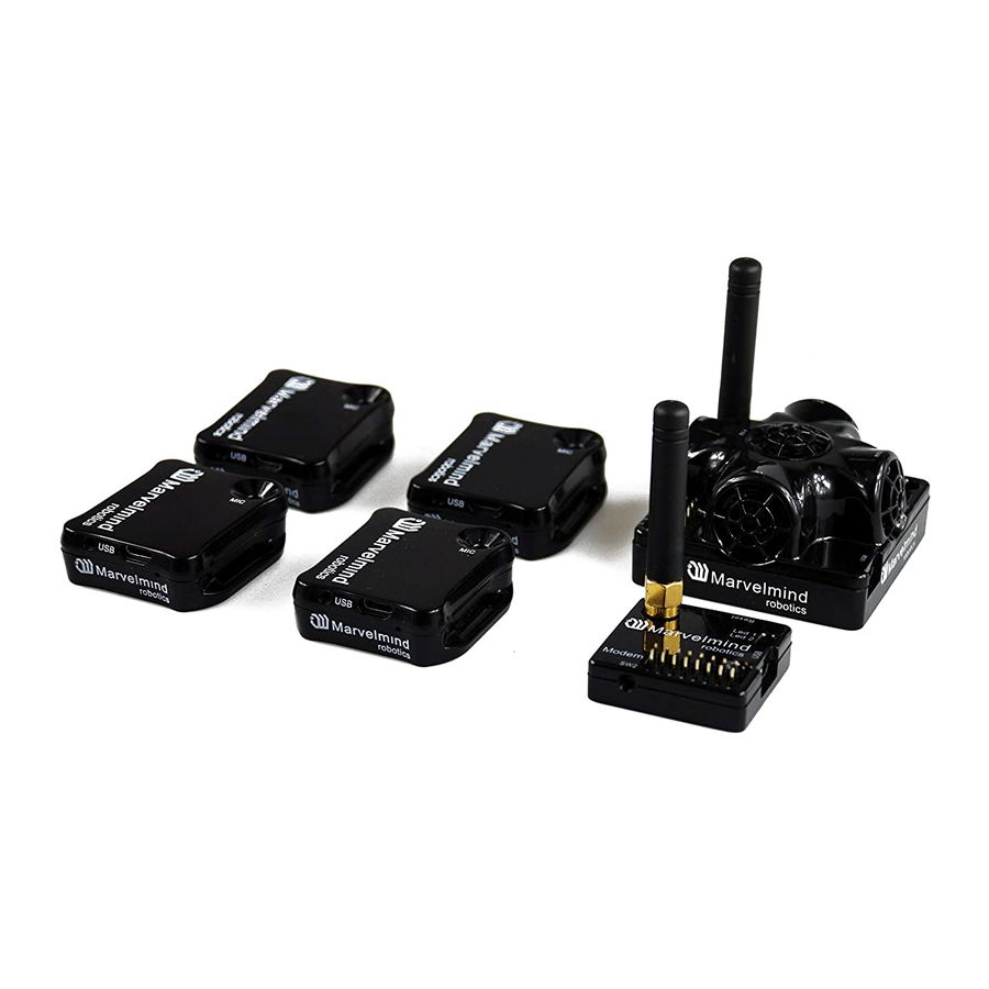
Basics of the system What’s in the box 2.1. Starter Set Super-NIA-3D: 5 x Super-beacons 1 x Modem/Router Mini-RX Starter Set: 4 x Mini-RX beacons 1 x Mobile beacon (HW v4.9) + IMU (aka “hedgehog”) 1 x Modem/Router *This is just an example of two starter sets. -
Page 13: Indoor Navigation System Architectures
2.2. Indoor Navigation System architectures Marvelmind Indoor Navigation System provides high-precision (±2cm) indoor coordinates for autonomous robots and systems (“indoor GPS”). A brief description of the key elements of the system is given on the scheme below. IA and NIA SW differs... - Page 14 Architecture comparison Non-Inverse Architecture Inverse Architecture (IA) (NIA) ‐ 1-4 autonomous robots/drones. Supported up to 250 ‐ Many mobile users (people, robots, VR). Supported up to 250 beacons Typical use cases beacons ‐ When mobile beacons are in quieter places ‐...
-
Page 15: Indoor "Gps" System Close-Up And Internal View
Indoor “GPS” System close-up and internal view 2.3. Here, you can see how system elements look like Super-beacon HW v4.9 modem (without housing) Mini-RX beacon Mini-TX... - Page 16 HW v4.9 beacon with Mini-TX size comparison Beacon Industrial-RX Beacon Industrial-Super...
-
Page 17: Control System (Dashboard)
System elements 3.1. Control system (Dashboard) Dashboard is a Windows/Linux app for setting up and tuning the system. It also allows to get the tracking data. General app for SW update and initial setting up the system Contains a lot of tracking display features Very deep tuning and setting abilities All new features available in the Dashboard app You can get data without the Dashboard, the whole system after setting up can work... -
Page 18: Stationary Beacon
3.2. Stationary beacon Usually, mounted on the walls or ceilings above the robot with ultrasonic sensors facing down—to provide the most robust unobstructed ultrasonic signal coverage to the robot. However, for automatic landing and indoor navigation of copters, for example, it is recommended to install mobile beacon horizontally on the belly of the copter so that the beacon would be looking downwards The position and orientation of the beacons should be chosen... -
Page 19: Mobile Beacon A.k.a. "Hedgehog
Mobile beacon a.k.a. “hedgehog” 3.3. The mobile and stationary beacons can be easily interchanged by selecting in the Dashboard The mobile beacons designed to be placed on a robotic vehicle, copter/drone, AGV, or helmet to trace its location. Formally speaking, location of the mobile beacon is traced—not the robot itself. -
Page 20: Modem
3.4. Modem Modem is the central controller of the system. It must always be powered when the Navigation System is working. It is recommended to use an active USB hub for that purpose or even a regular cellular phone USB power supply. A USB power bank can also be used The modem is also used to set up the system, monitor it, and interact with the Dashboard It can be placed anywhere within radio coverage for permanent radio... -
Page 21: Different Types Of Modems
Higher ingress protection - up to IP67 (optional) Super-Modem’s HW supports Super-Modem and Super-Super-Modem functionality for Multi-Modem architecture: https://marvelmind.com/pics/marvelmind_presentation.pdf Designed for outdoor and industrial applications External bendable antennas with SMA connector for extended radio range included Currently, supports license-free 915MHz ISM band (for example, US, Japan, Korea) and license-free SRD band 868MHz (EU, Russia). - Page 22 Exactly the same mounting holes as for Industrial beacons No battery inside – external power supply (+6..17V) required (for example, https://marvelmind.com/product/converter-220v-12v-ip67/). External battery is not practical for long- term due to relatively high and constant power consumption of 1.5-2W For optional IP67 version – extended working temperature range: -40C…+50C (provided by design –...
-
Page 23: Modem Hw V5.1
Modem HW v5.1 Modem HW v5.1 is a superior version of the Modem HW v4.9. Modem HW v5.1 looks almost the same as Modem HW v4.9. To distinguish it, check white sticker on the bottom Modem HW v5.1 and Modem HW v4.9 brief comparison: Modem HW v5.1 has more memory Modem HW v5.1 has higher radio range Modem HW v5.1 more sensitive... -
Page 24: Modem Hw V4.9
Modem HW v4.9 Modem HW v4.9 is a modem for the most of starter sets. It has balanced features and performance. Since Modem HW v5.1 released, Modem HW v4.9 will get bug-fixing SW updates only The modem is also used to set up the system, monitor it, and interact with the Dashboard It can be placed anywhere within radio coverage for permanent radio connection with all beacons—usually in the radius of up to 100 meters with... -
Page 25: Different Types Of Beacons
3.6. Different types of beacons Beacon comparison Here you can see more details about the different types of beacons: https://marvelmind.com/pics/marvelmind_beacons_comparison.pdf... -
Page 26: Super-Beacon
Super-Beacon The Super-Beacon is a dual-use beacon – it can both receive and transmit ultrasonic pulses. The Super-Beacon Beacon can be used in both the Non- Inverse Architecture (NIA) and the Inverse Architecture (IA): Architecture comparison. Supports license-free 915MHz ISM band (US) and license- free SRD band 868MHz (EU). - Page 27 Figure 2 Transmitting diagram (with sensors) Figure 3 Transmitting diagram (with sensors) Figure 5 Receiving diagram (with digital microphone) Figure 4 Receiving diagram (with digital microphone)
-
Page 28: External Microphone Extension
3.6.2.1. External microphone extension This modification of the Super-Beacon allows you to bring the receiving microphone to any place on the robot or clothing. Due to this, the microphone body itself will not interfere, and will not be visible. It allows you to create more accurate implantation. It is also possible to use 2 external microphones to calculate the direction, or to improve and increase the reception area. -
Page 29: External Microphones Schemes
3.6.2.2. External microphones schemes: There can be some beacons (from one of the batches) with mixed default microphone wires’ colors Figure 4 Connection for beacon with switched blue and yellow wires Figure 5 One external microphone connection... - Page 30 Figure 6 Two external microphone connection...
-
Page 31: Mini-Rx Beacon
Supports 868/915MHz radio only Light weighted Can be water-protected The component of the Marvelmind Helmet Marvelmind Watch It has 360° reception angle (horizontally) and 180° reception angle (vertically) Reception diagram. Digital microphone has about 360° (horizontally) and 180° (vertically) reception angle Mini-RX beacon may be over discharged. -
Page 32: External Microphone Extension
3.6.3.1. External microphone extension This modification of the Mini-RX beacon allows you to bring the receiving microphone to any place on the robot or clothing. Due to this, the microphone body itself will not interfere, and will not be visible. It allows you to create more accurate implantation. It is also possible to use 2 external microphones to calculate the direction, or to improve and increase the reception area. -
Page 33: Dual Microphones Modification
3.6.3.2. Dual microphones modification: Robot’s head External Microphone 1 Mini-RX beacon hidden External Microphone inside 47mm 210mm Figure 7 One external microphone with housing Figure 8 Two external microphones with housing... - Page 34 Figure 9 One external microphone soldering Figure 10 Two external microphones soldering...
-
Page 35: External Microphones Schemes
3.6.3.3. External microphones schemes: Figure 11 One external microphone connection Figure 12 Two external microphones connection... - Page 36 Figure 13 Two external microphones final view Figure 14 Two external microphones final view...
-
Page 37: Mini-Tx Beacon
Mini-TX beacon The Mini-TX is a TX only beacon, i.e. it can transmit, but cannot receive ultrasound Comparison to Beacon HW v4.9: Smaller size and lighter: 47x42x15mm & 25g vs. 55x55x33mm & 62g (or 55x55x64mm with antenna) TX only, i.e. Mini-TX can only transmit ultrasonic and cannot receive. Beacon HW v4.9 is dual use: can receive and transmit ultrasonic Battery –... -
Page 38: Beacon Industrial-Tx-Metal
Beacon Industrial-TX-Metal Do not disassemble the Industrial beacons. Otherwise, warranty will be lost TX-only beacon – can transmit ultrasonic, but can’t receive Electronics is IP67 protected Special IP67-protected 25kHz transducers External antenna with SMA connector for extended radio range Corresponding IP67 connectors (male part) included No battery inside Extended working temperature range from -40°C to +50°C (not tested, provided by design) - Page 39 Wide transmitting diagram Uploading Beacon’s Industrial-RX or Beacon’s Industrial-TX SW to Industrial Super-beacon may permanently damage Industrial Super-Beacon board. Determine carefully the version of your Industrial beacons: it may be built before September 2019 and after September 2019. If it is beacon from the late batch, you must use Industrial Super-beacon SW.
-
Page 40: Beacon Industrial-Rx
Beacon Industrial-RX Do not disassemble the Industrial beacons. Otherwise, warranty will be lost RX-only beacon – can receive ultrasonic, but can’t transmit it Electronics is IP67 protected Special IP67-membrane for ultrasonic sensor External antenna with SMA connector for extended radio range Corresponding IP67 connectors (male part) included No battery inside by default –... - Page 41 Wide reception diagram Uploading Beacon’s Industrial-RX or Beacon’s Industrial-TX SW to Industrial Super-beacon may permanently damage Industrial Super-beacon board. Determine carefully the version of your Industrial beacons: it may be built before September 2019 and after September 2019. If it is beacon from the late batch, you must use Industrial Super-beacon SW.
-
Page 42: Industrial Super-Beacon Metal-25Khz
Industrial Super-Beacon Metal-25kHz Do not disassemble the Industrial beacons. Otherwise, warranty will be lost Supports dual-use – RX and TX beacon. It can transmit on its native ultrasonic frequency (25kHz) and it can receive on any ultrasonic frequency via an embedded RX sensor –... -
Page 43: Beacon Hw V4.9
Beacon HW v4.9 Beacon HW v4.9 can be used in both the Non-Inverse Architecture (NIA) and in the Inverse Architecture (IA): NIA and IA comparison Reception diagram. Each sensor has about 90° reception angle: Figure 1 Transmitting diagram (with sensors) Figure 15 Transmitting diagram (with sensors) -
Page 44: Starter Set Super-Nia-3D
Setting up the system (NIA) 4.1. Starter Set Super-NIA-3D The steps below describe the very first time you set up of the system. Super-beacons and modem required. Unpack the system. Look at a similar unpacking video of HW v4.9. The videos have certain differences but the basic are the same: https://youtu.be/sOce7B2_6Sk... - Page 45 Run the Dashboard and update the SW for all beacons and modem using Dashboard => Firmware => Choose the file => Program If you see the message “Not found modem connection to computer through USB” in the Dashboard or your PC does not recognize beacons/modem, it usually means that the STM32 driver is not installed.
- Page 46 4.1.5.10. Press the RESET button on your beacon 4.1.5.11. In the upper left corner of the DfuSe program, you will see a device connected in the DFU mode 4.1.5.12. Choose the DFU driver (file) for the beacon 4.1.5.13. Click the UPGRADE button 4.1.5.14.
- Page 47 4.1.5.21. After uploading DFU driver by DfuSe short circuit pins as shown on the picture (for v4.9) and press Reset button 4.1.5.22. Modem will go to DFU mode. Press UPGRADE button in the DfuSe program 4.1.5.23. After a couple of seconds, the DFU will be uploaded to the modem. Make sure it takes 1-3 seconds and does not happen immediately.
- Page 48 Write down the beacon’s address for future use or change the address at your convenience as shown here Press the RESET button on your beacons and modem after programming After programming devices with the latest software, the modem and beacons are ready for use Place the stationary beacons high on the walls vertically in a way that will provide Write down the beacon’s height for future change in...
- Page 49 Top view: ≈6-10m Connect the modem/router via USB to a Windows PC with the Dashboard installed Run the Dashboard. In the left corner of the Dashboard, the modem should be shown as connected Wake up all beacons by selecting them on the Dashboard panel Only 4 stationary beacons may be in 1 submap.
- Page 50 Now you can check RSSI, voltage, ultrasonic filter settings, etc. on the panel on the right corner of the Dashboard Enter the height of stationary beacons. Choose beacon in the list and enter height value Enter the height for mobile beacon if you use 2D mode In the current version one modem supports 250 beacons (mobile + stationary combined).
- Page 51 If you see in the table some empty cells or marked yellow/red, it is an indication that distances between Some beacons are measured inconsistently or not measured at all. Try to re-position them because usually there is an obstruction of some sort in the between the beacons.
-
Page 52: Starter Set Hw V4.9
4.2. Starter Set HW v4.9 The steps below describe the very first time you set up of the system. Beacons HW v4.9 and modem required. Unpack the system. Watch the help video: https://youtu.be/sOce7B2_6Sk Charge all the beacons using USB cable. Full charging takes about 1-2 hours Turn the beacons on: Place DIP switches as shown on the picture below Reset button (on side) DIP switches... - Page 53 DFU programming or SW uploading is used when HEX SW uploading in the Dashboard cannot be used. For example, when you are updating from a very old SW version or when the SW includes major changes to the system and the only possible way to update the SW is via DFU programming 4.2.5.1.
- Page 54 4.2.5.12. Choose the DFU driver (file) for the beacon 4.2.5.13. Click the UPGRADE button 4.2.5.14. After a couple of seconds, the DFU will be uploaded to the beacon. Make sure it takes 1–3 seconds and does not happen instantly. Otherwise, the SW has not been uploaded correctly. If the DFU appears to upload immediately, check the "Choose"...
- Page 55 4.2.5.22. Modem will go to DFU mode. Press UPGRADE button in the DfuSe program 4.2.5.23. After a couple of seconds, the DFU will be uploaded to the modem. Make sure it takes 1-3 seconds and does not happen immediately. Otherwise, the SW has not been uploaded correctly. If the DFU appears to upload immediately, check the "Choose"...
- Page 56 Write down the beacon’s address for future use or change the address at your convenience as shown here Press the RESET button on your beacons and modem after programming After programming devices with the latest software, the modem and beacons are ready for use Place the stationary beacons high on the walls vertically in a way that will provide Write down the beacon’s height for future change in...
- Page 57 Top view: ≈6-10m Connect the modem/router via USB to a Windows PC with the Dashboard installed Run the Dashboard. In the left corner of the Dashboard, the modem should be shown as connected Wake up all beacons by selecting them on the Dashboard panel Only 4 stationary beacons may be in 1 submap.
- Page 58 Now you can check RSSI, voltage, ultrasonic filter settings, etc. on the panel on the right corner of the Dashboard Enter the height of stationary beacons. Choose beacon in the list and enter height value Enter the height for mobile beacon if you use 2D mode 4.2.1 In the current version one modem supports 250 beacons (mobile + stationary combined).
- Page 59 inconsistently or not measured at all. Try to re-position them because usually there is an obstruction of some sort in the between the beacons. If you have any problems – check Table of distances chapter 4.2.6 Make a service zone, clicking on the map with Shift+Left Mouse Button.
- Page 60 (Help video: https://www.youtube.com/watch?v=NHUnCtJIYXc)
-
Page 61: Starter Set Nia-01-3D
4.3. Starter Set NIA-01-3D The steps below describe the very first time you set up the system. Mini-RX, HW v4.9 beacons and modem required. Mini-RX has different HW and SW from HW v4.9. Use Mini-RX SW for Mini-RX beacons, HW v4.9’s SW for HW v4.9 Unpack the system. - Page 62 If you see the message “Not found modem connection to computer through USB” in the Dashboard or your PC does not recognize beacons/modem, it usually means that the STM32 driver is not installed. To install the driver, download it through the link in the top window in the Dashboard and run the installation file, then click on the link under and install the driver Make sure that that: You are programming the modem’s SW to the modem and the beacon’s SW to the beacon...
- Page 63 4.3.5.12. Choose the DFU driver (file) for the beacon 4.3.5.13. Click the UPGRADE button 4.3.5.14. After a couple of seconds, the DFU will be uploaded to the beacon. Make sure it takes 1–3 seconds and does not happen instantly. Otherwise, the SW has not been uploaded correctly. If the DFU appears to upload immediately, check the "Choose"...
- Page 64 4.3.5.22. Modem will go to DFU mode. Press UPGRADE button in the DfuSe program 4.3.5.23. After a couple of seconds, the DFU will be uploaded to the modem. Make sure it takes 1-3 seconds and does not happen instantly. Otherwise, the SW has not been uploaded correctly. If the DFU appears to upload immediately, check the "Choose"...
- Page 65 beacon’s Write down the address for future use or change the address at your convenience as shown here Press the RESET button on your beacons and modem after programming After programming devices with the latest software, the modem and beacons are ready for use Place the stationary beacons high on the walls vertically in a way that will provide Write down the beacon’s height for future change in...
- Page 66 Top view: ≈6-10m Connect the modem/router via USB to a Windows PC with the Dashboard installed Run the Dashboard. In the left corner of the Dashboard, the modem should be shown as connected Wake up all beacons by selecting them in the Dashboard on the panel It may take up to 7-10 seconds for the beacons to wake up Notice, that if the modem is not active and is not powered, the beacons will go into sleep mode automatically after 1 minute...
- Page 67 Enter the height of stationary beacons. Choose beacon in the list and enter height value Enter the height for mobile beacon if you use 2D mode In the current version one modem supports 250 beacons (mobile + stationary combined). If you do not see some of your connected beacons on the map, you may need to scroll to find their addresses Double click on the device to put it into sleep mode or wake it up Only 4 stationary beacons may be in 1 submap.
- Page 68 4.3.22.3. Now, enter measured (measure it with laser distance meter or so) value. That values would not change until you unfreeze or clear it. Even if beacons had been moved, distance would stay. Be careful with frozen cells because a small mistake can cause a significant impact on your tracking 4.3.22.4.
- Page 69 The system is now fully operational.
-
Page 70: Starter Set Nia-Smalldrone
4.4. Starter Set NIA-SmallDrone The steps below describe the very first time you set up the system. Mini-RX, Mini-TX beacons and modem required. Mini-RX and Mini-TX have different HW and SW from HW v4.9. Use Mini-RX SW for Mini-RX beacons, Mini-TX SW for Mini-TX beacons, HW v4.9’s SW for HW v4.9 Unpack the system. - Page 71 Run the Dashboard and update the SW for all beacons and modem using Dashboard => Firmware => Choose the file => Program If you see the message “Not found modem connection to computer through USB” in the Dashboard or your PC does not recognize beacons/modem, it usually means that the STM32 driver is not installed.
- Page 72 4.4.5.8. Run DfuSe 4.4.5.9. Press the RESET button on your beacon 4.4.5.10. In the upper left corner of the DfuSe program, you will see a device connected in the DFU mode 4.4.5.11. Choose the DFU driver (file) for the beacon 4.4.5.12.
- Page 73 4.4.5.18. After uploading DFU driver by DfuSe short circuit pins as shown on the picture (for v4.9) and press Reset button 4.4.5.19. Modem will go to DFU mode. Press UPGRADE button in the DfuSe program 4.4.5.20. After a couple of seconds, the DFU will be uploaded to the modem. Make sure it takes 1-3 seconds and does not happen instantly.
- Page 74 Write down the beacon’s address for future use or change the address at your convenience as shown here Press the RESET button on your beacons and modem after programming After programming devices with the latest software, the modem and beacons are ready for use Place the stationary beacons high on the walls vertically in a way that will provide beacon’s height for future change in...
- Page 75 Top view: ≈6-10m Connect the modem/router via USB to a Windows PC with the Dashboard installed Run the Dashboard. In the left corner of the Dashboard, the modem should be shown as connected Wake up all beacons by selecting them in the Dashboard on the panel It may take up to 7-10 seconds for the beacons to wake up Notice, that if the modem is not active and is not powered, the beacons will go into sleep mode automatically after 1 minute...
- Page 76 Enter the height for mobile beacon if you use 2D mode In the current version one modem supports 250 beacons (mobile + stationary combined). If you do not see some of your connected beacons on the map, you may need to scroll to find their addresses Double click on the device to put it into sleep mode or wake it up Only 4 stationary beacons may be in 1 submap.
- Page 77 4.4.22.1. Open the Dashboard. You will see the table of distances 4.4.22.2. Use right mouse click on cell you want to enter the distance. Additional menu will open. There you can control the table of distances. Choose Enter distance for pair to enter the value 4.4.22.3.
- Page 78 If you see on the devices’ panel in the Dashboard that the beacon is colored orange, it means there are some differences in some of the settings between beacons. For example, some sensors may be off or some ultrasonic or radio settings may be different.
-
Page 79: Starter Set Nia-02-2D
4.5. Starter Set NIA-02-2D The steps below describe the very first time you set up the system. Mini-RX, Mini-TX beacons and modem required. Mini-RX and Mini-TX have different HW and SW from HW v4.9. Use Mini-RX SW for Mini-RX beacons, Mini-TX SW for Mini-TX beacons, HW v4.9’s SW for HW v4.9 Unpack the system. - Page 80 Run the Dashboard and update the SW for all beacons and modem using Dashboard => Firmware => Choose the file => Program If you see the message “Not found modem connection to computer through USB” in the Dashboard or your PC does not recognize beacons/modem, it usually means that the STM32 driver is not installed.
- Page 81 4.5.5.5. In the upper left corner of the DfuSe program, you will see a device connected in the DFU mode 4.5.5.6. Choose the DFU driver (file) for the beacon 4.5.5.7. Click the UPGRADE button 4.5.5.8. After a couple of seconds, the DFU will be uploaded to the beacon. Make sure it takes 1–3 seconds and does not happen instantly.
- Page 82 4.5.5.15. Modem will go to DFU mode. Press UPGRADE button in the DfuSe program 4.5.5.16. After a couple of seconds, the DFU will be uploaded to the modem. Make sure it takes 1-3 seconds and does not happen instantly. Otherwise, the SW has not been uploaded correctly. If the DFU appears to upload immediately, check the "Choose"...
- Page 83 Write down the beacon’s address for future use or change the address at your convenience as shown here Press the RESET button on your beacons and modem after programming After programming devices with the latest software, the modem and beacons are ready for use Place the stationary beacons high on the walls vertically in a way that will provide beacon’s height for future change in...
- Page 84 Top view: ≈6-10m Connect the modem/router via USB to a Windows PC with the Dashboard installed Run the Dashboard. In the left corner of the Dashboard, the modem should be shown as connected Wake up all beacons by selecting them in the Dashboard on the panel It may take up to 7-10 seconds for the beacons to wake up Notice, that if the modem is not active and is not powered, the beacons will go into sleep mode automatically after 1 minute...
- Page 85 Enter the height of stationary beacons. Choose beacon in the list and enter height value Enter the height for mobile beacon if you use 2D mode In the current version one modem supports 250 beacons (mobile + stationary combined). If you do not see some of your connected beacons on the map, you may need to scroll to find their addresses Double click on the device to put it into sleep mode or wake it up Only 4 stationary beacons may be in 1 submap.
- Page 86 4.5.22.3. Now, enter measured (measure it with laser distance meter or so) value. That values would not change until you unfreeze or clear it. Even if beacons had been moved, distance would stay. Be careful with frozen cells because a small mistake can cause a significant impact on your tracking 4.5.22.4.
- Page 87 Freeze the map by clicking the button. Stationary beacons will stop measuring relative distances and will be ready to measure distance from the mobile beacon(s) Turn on and wake up the mobile beacon following the same steps as with the stationary beacon: https://youtu.be/A4aRsjH2-_E If you see on the devices’...
-
Page 88: Starter Set Industrial-Nia-01
4.6. Starter Set Industrial-NIA-01 The steps below describe the first set up of the system. This is a Non-Inverse Architecture. You can find the description and comparison of architectures here. Pay attention: Industrial beacons have different HW and SW from HW v4.9. It has different connectors, reset and DFU activation. - Page 89 Magnetic Reset side Magnetic DFU switch side Run the Dashboard and update the SW for all beacons and modem using Dashboard => Firmware => Choose the file => Program If you see the message “Not found modem connection to computer through USB” in the Dashboard or your PC does not recognize beacons/modem, it usually means that the STM32 driver is not installed.
- Page 90 Download DfuSe Here you will find different versions of DfuSe. v3.0.4 or v3.0.5, whichever works the best for your Windows: DfuSe v3.0.4 DfuSe v.3.0.5 DFU Programming: Uploading Beacon Industrial’s (Not super) DFU software to Industrial Super- Beacon hardware make permanently damage for Industrial Super-Beacon board. Be double attentive with update 4.6.5.1.
- Page 91 4.6.5.6. Choose the DFU driver (file) for the beacon 4.6.5.7. Click the UPGRADE button 4.6.5.8. After a couple of seconds, the DFU will be uploaded to the beacon. Make sure it takes 1–3 seconds and does not happen instantly. Otherwise, the SW has not been uploaded correctly. If the DFU appears to upload immediately, check the "Choose"...
- Page 92 4.6.5.16. After a couple of seconds, the DFU will be uploaded to the modem. Make sure it takes 1-3 seconds and does not happen instantly. Otherwise, the SW has not been uploaded correctly. If the DFU appears to upload immediately, check the "Choose" button you used or change the version of DfuSe SW to a different one.
- Page 93 Write down the beacon’s address for future use or change the address at your convenience as shown here Press the RESET (Industrial beacons have magnetic re button on your beacons and modem after programming After programming devices with the latest software, the modem and beacons are ready for use Place the stationary beacons high on the walls vertically in a way that will provide Write down the beacon’s height for future change in...
- Page 94 Top view: ≈6-10m Connect the modem/router via USB to a Windows PC with the Dashboard installed Run the Dashboard. In the left corner of the Dashboard, the modem should be shown as connected Wake up all beacons by clicking on the buttons in the Dashboard on the panel It may take up to 7-10 seconds for the beacons to wake up Notice, that if the modem is not active and is not powered, the beacons will go into sleep mode automatically after 1 minute...
- Page 95 Enter the height of stationary beacons. Choose beacon in the list and enter height value Enter the height for mobile beacon if you use 2D mode In the current version one modem supports 250 beacons (mobile + stationary combined). If you do not see some of your connected beacons on the map, you may need to scroll to find their addresses Double click on the device to put it into sleep mode or wake it up Only 4 stationary beacons may be in 1 submap.
- Page 96 4.6.23.3. Now, enter measured (measure it with laser distance meter or so) value. That values would not change until you unfreeze or clear it. Even if beacons had been moved, distance would stay. Be careful with frozen cells because a small mistake can cause a huge impact on your tracking 4.6.23.4.
- Page 97 The system is now fully operational...
-
Page 98: Starter Set Super-Mp-3D
Setting up the system (IA) 5.1. Starter Set Super-MP-3D The steps below describe the very first time you set up of the system. Super-Beacons with different ultrasonic frequencies and modem required. This is Inverse Architecture. Super-Beacons should have different frequencies. Use IA Software ONLY. - Page 99 Run the Dashboard and update the SW for all beacons and modem using Dashboard => Firmware => Choose the file => Program If you see the message “Not found modem connection to computer through USB” in the Dashboard or your PC does not recognize beacons/modem, it usually means that the STM32 driver is not installed.
- Page 100 5.1.5.6. Choose the DFU driver (file) for the beacon. 5.1.5.7. Click the UPGRADE button 5.1.5.8. After a couple of seconds, the DFU will be uploaded to the beacon. Make sure it takes 1–3 seconds and does not happen instantly. Otherwise, the SW has not been uploaded correctly. If the DFU appears to upload immediately, check the "Choose"...
- Page 101 5.1.5.16. After a couple of seconds, the DFU will be uploaded to the modem. Make sure it takes 1-3 seconds and does not happen immediately. Otherwise, the SW has not uploaded correctly. If the DFU appears to upload immediately, check the "Choose" button you used or change the version of DfuSe SW to a different one.
- Page 102 Write down the beacon’s address for future use or change the address at your convenience as shown here Press the RESET button on your beacons and modem after programming. After programming devices with the latest software, the modem and beacons are ready for use.
- Page 103 Top view: ≈6-10m Connect the modem/router via USB to a Windows PC with the Dashboard installed. Run the Dashboard. In the left corner of the Dashboard, the modem should be shown as connected. Wake up all beacons by clicking on the buttons in the Dashboard on the panel. It may take up to 7-10 seconds for the beacons to wake up Notice, that if the modem is not active and is not powered, the beacons will go into sleep mode automatically after 1 minute...
- Page 104 Only 4 stationary beacons may be in 1 submap. If you wake up more beacons, create new submap for them. Or it won’t be displayed on the map and in the table of distances. Enter the height of stationary beacons. Choose beacon in the list and enter height value...
- Page 105 Enter the height for mobile beacon if you use 2D mode In the current version one modem supports 250 beacons (mobile + stationary combined). If you do not see some of your connected beacons on the map, you may need to scroll to find their addresses Double click on the device both to put it into sleep mode and to wake it up The map will form and zoom in automatically If the map does not form well, check the table of distances in the left corner of the...
- Page 106 The system is now fully operational.
-
Page 107: Starter Set Ia-01-2D
5.2. Starter Set IA-01-2D The steps below describe the very first time you set up of the system. Mini-RX-beacon, HW v4.9 beacons and modem required. This is Inverse Architecture. Beacons HW v4.9 should have different frequencies. Use IA Software ONLY. You can’t just switch HW v4.9 beacon to another frequency, it is HW depended Ultrasonic can't be changed to default. - Page 108 Update all the beacons You need Inverse Architecture SW (go to marvelmind_SW_xxx_xx_xx\Software_ia) Run the Dashboard and update the SW for all beacons and modem using Dashboard => Firmware => Choose the file => Program If you see the message “Not found modem connection to computer through USB” in the Dashboard or your PC does not recognize beacons/modem, it usually means that the STM32 driver is not installed.
- Page 109 Press the RESET button on your beacon. In the upper left corner of the DfuSe program, you will see a device connected in the DFU mode. Choose the DFU driver (file) for the beacon. Click the UPGRADE button After a couple of seconds, the DFU will be uploaded to the beacon. Make sure it takes 1–3 seconds and does not happen instantly.
- Page 110 After a couple of seconds, the DFU will be uploaded to the modem. Make sure it takes 1-3 seconds and does not happen immediately. Otherwise, the SW has not uploaded correctly. If the DFU appears to upload immediately, check the "Choose"...
- Page 111 Write down the beacon’s address for future use or change the address at your convenience as shown here Press the RESET button on your beacons and modem after programming. After programming devices with the latest software, the modem and beacons are ready for use.
- Page 112 Top view: ≈6-10m Connect the modem/router via USB to a Windows PC with the Dashboard installed. Run the Dashboard. In the left corner of the Dashboard, the modem should be shown as connected. Wake up all beacons by clicking on the buttons in the Dashboard on the panel. It may take up to 7-10 seconds for the beacons to wake up Notice, that if the modem is not active and is not powered, the beacons will go into sleep mode automatically after 1 minute...
- Page 113 Enter the height of stationary beacons. Choose beacon in the list and enter height value Enter the height for mobile beacon if you use 2D mode In current version one modem supports 250 beacons (mobile + stationary combined). If you do not see some of your connected beacons on the map, you may need to scroll to find their addresses.
- Page 114 5.2.21.4. Now, enter measured (measure it with laser distance meter or so) value. That values would not change until you unfreeze or clear it. Even if beacons had been moved, distance would stay. Be careful with frozen cells because a small mistake can cause a huge impact on your tracking.
- Page 115 The system is now fully operational.
-
Page 116: Starter Set Ia-02-3D
5.3. Starter Set IA-02-3D The steps below describe the very first time you set up of the system. Mini-RX-beacon, HW v4.9 beacons and modem required. This is Inverse Architecture. Beacons HW v4.9 should have different frequencies. Use IA Software ONLY. You can’t just switch HW v4.9 beacon to another frequency, it is HW depended Ultrasonic can't be changed to default. - Page 117 You need Inverse Architecture SW (go to marvelmind_SW_xxx_xx_xx\Software_ia) Run the Dashboard and update the SW for all beacons and modem using Dashboard => Firmware => Choose the file => Program If you see the message “Not found modem connection to computer through USB” in the Dashboard or your PC does not recognize beacons/modem, it usually means that the STM32 driver is not installed.
- Page 118 5.3.5.5. In the upper left corner of the DfuSe program, you will see a device connected in the DFU mode. 5.3.5.6. Choose the DFU driver (file) for the beacon. 5.3.5.7. Click the UPGRADE button 5.3.5.8. After a couple of seconds, the DFU will be uploaded to the beacon. Make sure it takes 1–3 seconds and does not happen instantly.
- Page 119 5.3.5.15. Modem will go to DFU mode. Press UPGRADE button in the DfuSe program 5.3.5.16. After a couple of seconds, the DFU will be uploaded to the modem. Make sure it takes 1-3 seconds and does not happen immediately. Otherwise, the SW has not uploaded correctly. If the DFU appears to upload immediately, check the "Choose"...
- Page 120 Write down the beacon’s address for future use or change the address at your convenience as shown here Press the RESET button on your beacons and modem after programming. After programming devices with the latest software, the modem and beacons are ready for use.
- Page 121 Top view: ≈6-10m Connect the modem/router via USB to a Windows PC with the Dashboard installed. Run the Dashboard. In the left corner of the Dashboard, the modem should be shown as connected. Wake up all beacons by clicking on the buttons in the Dashboard on the panel. It may take up to 7-10 seconds for the beacons to wake up Notice, that if the modem is not active and is not powered, the beacons will go into sleep mode automatically after 1 minute...
- Page 122 Enter the height of stationary beacons. Choose beacon in the list and enter height value Enter the height for mobile beacon if you use 2D mode 5.3.1 In current version one modem supports 250 beacons (mobile + stationary combined). If you do not see some of your connected beacons on the map, you may need to scroll to find their addresses.
- Page 123 Only 4 stationary beacons may be in 1 submap. If you wake up more beacons, create new submap for them. Or it won’t be displayed on the map and in the table of distances. Build the map: Beacons with different frequencies are not able to build the map automatically, so you have to build it manually 5.3.21.1.
- Page 124 Freeze submap and by clicking the button. Stationary beacons will stop measuring relative distances and will be ready to measure distance from the mobile beacon(s). freeze submap Turn on and wake up the mobile beacon following the same steps as with the stationary beacon: https://youtu.be/A4aRsjH2-_E If you see on the devices’...
-
Page 125: Dashboard General View
Dashboard menu and parameters 6.1. Dashboard general view This picture shows the Dashboard’s general interface and items’ positions Diagnostics messages Modem/beacon’s Table of Visualization window distances window settings bar Ceiling and Visualization mirroring buttons settings Modem Modem/beacon’s Devices list quick control panel Map settings... -
Page 126: Diagnostics Messages Window
6.2. Diagnostics messages window Diagnostic messages window is an area where important system’s messages appears. It may contain a lot of useful information. Diagnostics window is placed on the top of the Dashboard. If the field is empty, that means that system didn’t find any issues for the launch. If you have any messages, please check it carefully and fix the issue. -
Page 127: Table Of Distances
6.3. Table of distances Table of distances shows the measured distance between all beacons. The map and its graphical visualization depend on distances, which is a very important part of the system. There are two ways of measuring: Measuring by ultrasound (automatic) Measuring by user (manual) Measuring by ultrasound is impossible for Mini-RX and Industrial-RX beacons In noisy cases and cases with long distances it is better to use manual input... - Page 128 6.3.2.3. Now, cells are frozen. That values would not change until you unfreeze it. Even if beacons had been moved, distance would stay. Be careful with frozen cells because a small mistake can cause a huge impact on your tracking 6.3.2.4.
-
Page 129: Devices List
6.4. Devices list Devices list contains information about all the beacons in the system. It also allows to search, add and delete it. Devices in this section are divided into two types: Stationary beacon (beacon) Mobile beacon (hedge) Devices list allows user to manage devices Use double click to put beacon into sleep mode Stationary beacon (beacon) Press right mouse button and additional menu will open... -
Page 130: Visualization Settings
6.5. Visualization settings Visualization settings window has some functions to control visualization process: Clear map – clear all movement path Dots timeout – time of path’s existence (Video: Help: Dots timeout) Dots size mode – size of dots Save screenshot – files save to Dashboard’s folder/screenshots Freeze screen –... -
Page 131: Map Settings
6.6. Map Settings Map Settings offer some helpful tools: Save map – saves map as .ini file into Dashboard folder/maps Load map – loads map from .ini format file Erase map – erases map and clears it... -
Page 132: Modem/Beacon's Quick Control Panel
Modem/beacon’s quick control panel 6.7. Control panel allows user to interact with devices. It can work with one device, or with all devices in the system. List of functions: Reset – Resets device Sleep – Send device asleep (battery economy mode) Wake up –... -
Page 133: Ceilling And Mirroring Buttons On The Dashboard
6.8. CEILLING and MIRRORING buttons on the Dashboard The MIRRORING button allows the map to be display as a mirror reflection The CEILING button shows where the mobile beacon is located with respect to the stationary beacons When the arrow points up, it means that the mobile beacon is below the stationary beacons When the arrow points down, it means that the mobile beacon is above the stationary beacons... -
Page 134: Detailed Settings
6.9. Detailed settings This bar allows user to adjust devices very precisely. It contains a lot of parameters for advanced usage Modem Settings Unique processor ID for each device (beacon or modem) Location update rate settings: 1/20Hz – 16Hz+. Notice that real update rate may be limited by distances between beacons or radio profile Internal filter. - Page 135 Power supply voltage of the device 5V+-0.2V is OK Time from the latest reset Measured temperature of the processor’s crystal Strength of the radio signal from modem to beacons and vice versa. Maintain in the range of -25dBm to -80..- 90dBm.
- Page 136 Advanced settings Enabling will allow direction along with location:...
- Page 137 Parameters of radio Real carrier frequency Selected radio profile with a set of profile settings. Choose between 38kbps (better range and interference immunity, but slower); 153kbps – balanced; and 500kbps – the fastest, but the lowest radio range and least immune to interference Logical address of the device.
- Page 138 Radio profile settings. No need to change manually. Only for advanced users Radio profile settings. No need to change manually. Only for advanced users Radio profile settings. No need to change manually. Only for advanced users Radio profile settings. No need to change manually. Only for advanced users Radio profile settings.
-
Page 139: Beacon's Settings
Beacon’s settings Unique CPU ID Enable for mobile beacon and disable for stationary beacon Measured voltage of internal battery Height – must be set for stationary beacons. Must also be set for mobile beacons in 1D or 2D modes Time from the latest reset... - Page 140 Processor’s crystal’s temperature Strength of the radio signal from this beacon to the modem, i.e. how the modem “hears” the beacon over radio. Keep below -25dBm and above -80..90dBm to avoid losses of packets. Lower end depends on radio profile and interference Select radio frequency band according to your HW: 433MHz or 915MHz Real carrier frequency...
- Page 141 Calibration settings of embedded IMU: X shift Calibration settings of embedded IMU: Y shift Calibration settings of embedded IMU: Z shift Calibration settings of embedded IMU: X scale Calibration settings of embedded IMU: Y scale Calibration settings of embedded IMU: Z scale...
- Page 142 Parameters of radio Real carrier frequency Radio profile that is linked with many radio settings below. Helps to set them at once by choosing the profile. See similar in modem for more info Device address – shall be set for each beacon different under one modem One of the pre-selected frequency channels Radio profile settings.
- Page 143 Radio profile settings. No need to change manually. Only for advanced users Radio profile settings. No need to change manually. Only for advanced users Radio profile settings. No need to change manually. Only for advanced users Radio profile settings. No need to change manually. Only for advanced users Radio profile settings.
- Page 144 Ultrasound TX-RX – regular mode. Use it. The rest - internal Power saving features. If not sure, keep default Power saving features. If not sure, keep default Frequency of ultrasonic pulses – set according to your HW 50% - default. 1% … 99% lower strength of ultrasonic. Keep default Number of ultrasonic pulses the TX beacon emits.
- Page 145 AGC settings. For advanced users only AGC settings. For advanced users only AGC settings. For advanced users only AGC settings. For advanced users only Deep ultrasonic trigger settings. For special cases only Deep ultrasonic trigger settings. For special cases only Keep ADC Deep ultrasonic trigger settings.
- Page 146 Deep ultrasonic trigger settings. For special cases only Deep ultrasonic trigger settings. For special cases only Deep ultrasonic trigger settings. For special cases only Deep ultrasonic trigger settings. For special cases only Deep ultrasonic trigger settings. For special cases only...
- Page 147 Deep AGC settings. For special cases only Deep AGC settings. For special cases only Deep AGC settings. For special cases only Deep AGC settings. For special cases only Enable/disable sensor RX1 in map building mode Enable/disable sensor RX2 in map building mode...
- Page 148 Enable/disable sensor RX3 in map building mode Enable/disable sensor RX4 in map building mode Enable/disable sensor RX5 in map building mode Enable/disable sensor RX1 in map frozen/regular work mode Enable/disable sensor RX2 in map frozen/regular work mode Enable/disable sensor RX3 in map frozen/regular work mode Enable/disable sensor RX4 in map frozen/regular work mode...
- Page 149 Interfaces Speed of UART in hedgehog mode Type of protocol Enable or disable receiving raw IMU data with IMU update rate (100Hz) Enable or disable receiving IMU+ultrasonic sensor fusion data with IMU update rate (100Hz) Georeferencing The same as with modem The same as with modem Misc.
-
Page 150: Radio Frequency Band And Carrier Frequency
6.10. Radio frequency band and Carrier frequency For devices with HW 433 MHz allowable Radio bands 315 and 433, For devices with HW 915 MHz allowable Radio bands 868 and 915, but when using antennas at 433 MHz it is possible to use both 315 and 433 MHz *Mini-RX beacons and Super-Beacons are 868/915MHz only It is possible to change the frequency of radio, but radio performance can be severely degraded. -
Page 151: Different Hedgehog Colors In The Dashboard
6.11. Different hedgehog colors in the Dashboard You can choose any color for your hedge, but it still has some permanent colors, which inform you about some tracking issues: Blue - normal mode and confident tracking Orange - system provides the best location data possible, but confidence is lower than blue - lost radio packets –... -
Page 152: Different Beacons' Colors In The Dashboard
6.12. Different beacons’ colors in the Dashboard Beacons can have different ultrasonic frequency. Because of that, they have different colors to make it easy to distinguish it: Stationary beacons – Green center – Mobile beacons – Dark blue center – Examples: Stationary beacons: 19KHz... -
Page 153: Super-Modem's Sw Update And Configuration Description
Low level firmware High level software for integrated Raspberry Pi single-board computer Low level firmware is placed in general software package with all Marvelmind software in ‘Super-Modem’ folder. This firmware can be updated via dashboard (hex file) or via DFU (dfu file) like other firmware in the package. -
Page 154: How To Update Super-Modem's Sw
Do not disassemble the Super-Modem before you check the SW version installed. First of all, check if the SW version of your Super-Modem is up to date (Latest version on the page). If not – update the software as described below Marvelmind Downloads Follow the steps below to update Super-Modem’s SW. 7.1.2.1. -
Page 155: Super-Modem's Configuration
SW version of your Super-Modem is up to date (Latest version on the page). If not – update the software as described below Marvelmind Downloads Marvelmind Super-Modem contains Raspberry Pi single-board computer with corresponding software. Some settings can be modified via configuration files on the micro-SD card inserted in the Super-Modem. - Page 156 7.1.3.1. Following settings are available: In file “network_options”: wifi_network – name (SSID) of WiFi network to connect wifi_password – password (PSK) for this network In file “stream_options”: udp_destination_ip – IP address in local network where Super-Modem will stream data udp_destination_port – UDP port where Super-Modem will stream data...
-
Page 157: Sw Update (Usb/Radio/Dfu)
7.2. SW update (USB/Radio/DFU) This chapter describes three general ways of SW update. Regular - using USB connection, or Radio connection. And SW update for special cases (if SW version gap is very big, or regular SW update do not work) – DFU Programming. SW update via USB Usually, SW update via USB is used for the very first time you starting up the system. -
Page 158: Sw Update Via Dfu Programming
Wait until beacon update finishes Repeat for all your beacons SW update via DFU Programming Not applicable to “Outdoor” versions of originally non-outdoor versions Usually, SW update happen using regular USB or Radio SW update. But in case when you didn’t update your system for a long time (and get a big SW version gap), or you faced with some unexpectable troubles –... - Page 159 Mini-TX beacon: Reset button (on the other side) Disassemble DIP switches Carefully Industrial beacons have no switches and reset buttons, but they have magnetic DFU switch and magnetic Reset button: Industrial Super-Beacon-Plastic: Magnetic Reset side Magnetic DFU switch side Industrial Super-Beacon Metal-25kHz: Magnetic Reset side Magnetic DFU switch side...
- Page 160 Beacon Industrial-RX: Magnetic Reset side Magnetic DFU switch side How to enter into DFU mode and Reset different types of Modems: Modem HW v5.1: Hardware Reset button (on side) DFU mode pins Modem HW v4.9: Hardware Reset button (on side) DFU mode pins Super-Modem: Magnetic Reset side...
- Page 161 DFU Programming process: Enter device into DFU Mode: For regular and non-Industrial versions of beacons – switch DIP switches into positions shown on the picture (both up) and press the Reset button – device will go into DFU mode For Industrial versions of beacon and Super-Modem – attach one magnet to the DFU switch side, and attach for 1 second the second magnet to the Reset side of the device –...
- Page 162 Exit from the DFU mode: For regular and non-Industrial versions of beacons – switch DIP switches into positions shown on the picture (Left – down, right – up) and press the Reset button – device will exit from DFU mode For Industrial versions of beacon and Super-Modem –...
-
Page 163: Licenses
We added the licenses system. Now, you can order some additional features. It is not available in the basic Dashboard version, but you can easily purchase it if necessary. You can see the list on Marvelmind.com -> Products To order: Go to Marvelmind.com ->... - Page 164 Press Order licenses. Dashboard will generate a text Send generated text to info@marvelmind.com We will generate the license key and send to you via email Place the license key into Dashboard/Licenses folder: Connect device to the Dashboard via USB Go to Licenses → View/activate licenses Choose "Open license key"...
-
Page 165: Dashboard Monitoring Mode
7.4. Dashboard Monitoring Mode Dashboard Monitoring Mode is a mode which allows you to observe tracking without any ability to control and modify the system. Now, you can divide permissions between users for avoidance of accidental change of any settings and corrupting the system. That is something like safety button. This is the first version of Dashboard Monitoring Mode. -
Page 166: Geofencing Zones
7.5. Geofencing zones Geofencing zones is a subset of zones which can be created to prevent people crossing dangerous zones. Zones violations leads to alarm and will be written into CSV-file. How to create geofencing zone: Unfreeze map, submap may be frozen Choose submap (Left mouse click on its icon) and Right mouse button click on the map ->... - Page 167 Create a zone using Shift+Left mouse click and clicking on map, click on point removes it You can tune zone with entering distance and entering time. If zone created, press Save and close to save zone Freeze map...
- Page 168 Zone created and ready to work. If mobile beacon crosses zone for tuned distance and tuned time, that violation will be recorded to CSV-file, and hedgehog will be colored in the Dashboard...
-
Page 169: Floors Feature (Fn0011)
7.6. Floors feature (FN0011) The general view Floor feature allows to build complicated multi-level maps. Every submap correspond some height, height corresponds to floors. List of layers (floors) Show all layers (floors) Show no layers (floors) Show all objects (even if they are out of floors’ coordinates) Beacons’... -
Page 170: Floor Settings
Floor Settings Every floor has its own adjustable height and its own floor plan Use right mouse button on the floor area to see an additional menu. There you can change floor’s height. You can also insert your floorplan for that floor (.png, .jpeg, .bmp, .tiff) Floor 4 and 5 are enabled:... - Page 171 Floor 5 is enabled: Floor 4 is enabled:...
-
Page 172: Loading The Floorplan (Substrate)
Loading the Floorplan (Substrate) Right mouse button click on the floor -> Load floorplan -> Choose file (.png, .jpeg, .bmp, .tiff). When the picture is loaded, you can drag the beacons to the points where they are actually located. After dragging two beacons, the picture with beacons will be combined in scale Help video: https://www.youtube.com/watch?v=NHUnCtJIYXc... -
Page 173: Submap Settings
7.7. Submap Settings Every submap has its own settings. Which beacon will have origin (0; 0; 0) coordinates Addresses of beacons which are building this submap 3D (X; Y; Z) Tracking mode for this submap To enable “Vertical submap for stable Z”... -
Page 174: Axis Rotation Feature (Fn0002)
7.8. Axis rotation feature (FN0002) General view Axis extension allows user to rotate the map. There are 90° gaps between views. It helps in case of multifloor tracking, when it is important to have a side view. There are 3 directions of view: To change view, click on the icon Examples of view: Y, X... - Page 175 Z, X...
-
Page 176: Vertical Submaps Feature (Fn0003)
7.9. Vertical submaps feature (FN0003) Vertical submap is a new feature for drone flights or some other specific cases. It gives the user an opportunity to get solid Z data for vertical movement Example: The drone flight... -
Page 177: How To Build Vertical Submap For Stable Z
How to build vertical submap for stable Z: 7.9.1.1. For this configuration you need 6 stationary beacons 7.9.1.2. Place 4 beacons on the ground, facing each other. (make a square, where the edge points are beacons, looking in the center) 7.9.1.3. - Page 178 7.9.1.12. Enter the corner value (90° usually) Choose submap 2 and enable “Only for Z coordinates” mode 7.9.1.13. 7.9.1.14. Change Limitation distance value 7.9.1.15. Change views and check the map 7.9.1.16. Wake up mobile beacon 7.9.1.17. Track...
-
Page 179: Handover Zones Setting
7.10. Handover Zones Setting User must setup handover zones between submaps to guarantee handover quality for complex maps with multi-floor and similar. How to setup handover zones: Choose any submap Use Alt + Left mouse click on the other submap’s service zone border (neighboring) Now, neighboring service zones are colored with green (dark green for chosen submap and light green for neighboring submaps) Alt + Left mouse click... -
Page 180: Submaps Feature (Fn0004)
10,000..300,000 or more) based on smaller submaps (30..1000m2). A submap is a part of the map. It includes a subset of used beacons covering part of the navigation area. Current version of Marvelmind system can include up to 10 submaps. Please also check our help... -
Page 181: Starting Submaps
Starting submaps Hedgehogs do not belong to any submap and can move between sub-map areas. Hedgehogs can be served by multiple submaps at the same time. By default, the map consists of a single submap (Submap0) 7.11.1.1. After adding new beacons to the system (waking them up), they appear in the first not frozen submap or in Submap0 if all beacons are frozen Pressing the “+”... - Page 182 7.11.1.5. The system after adding beacons to the Submap0, adding new submap and the selection of Submap0 7.11.1.6. Now we have 4 beacons, all in Submap0 (it can be seen near the table of distances) 7.11.1.7. When the submap selected, the context menu of beacons buttons (available by right clicking the mouse) have the functions of adding and removing the beacons from the submap.
- Page 183 7.11.1.10. Pressing the “freeze map” button when the submap is selected will only freeze the selected submap. Pressing the “freeze map” button when the modem button is selected will freeze all submaps. 7.11.1.11. Now we have two good submaps, but they are not correctly located relative to each other.
- Page 184 7.11.1.16. Submaps can be removed from the system by using the context menu of the submap selection button (available with a right mouse click) M1/M2 parameter used for precise superposing submaps which do not have common beacons. This means that submaps cannot be aligned automatically To align submaps: Build the system like in previous instruction...
- Page 185 Replace hedgehog to 1 or 2 points and repeat replacing submap for better superposing 7.11.1.17. The next step is to set Service zones, which are zones where tracking is possible. If a mobile beacon is out of a service zone it cannot be tracked.
-
Page 186: How To Create A Service Zone
How to create a service zone: 7.11.2.1. Choose submap (click on the submap icon) 7.11.2.2. Use SHIFT + Left mouse button on the map to create point. 7.11.2.3. Use SHIFT + Left mouse button on the point to delete it. 7.11.2.4. -
Page 187: Paired Beacons (Fn0005)
7.12. Paired beacons (FN0005) Two hedgehogs can be paired and work together as a single beacon without update rate reduction. In this case you get mot only location, but direction too. Moreover, each beacon streams out in this mode not only its own location, but direction where the pair is facing. -
Page 188: Map Settings
7.13. Map settings Map Settings offer some helpful tools: Save map – saves map as .ini file into Dashboard folder/maps Load map – loads map from .ini format file Erase map – erases map and clears it... -
Page 189: Background Color
7.14. Background color Starting from v6.200 Dashboard supports background color change. This is a small feature that helps make tracking look better. If you uploaded a floorplan and it is white, you can tune Dashboard’s background color to make it suit. How to choose background color: Load floorplan Right mouse button click on the background... - Page 190 Choose color and press “OK” Color applied. Now, background matches floorplan...
-
Page 191: Hedge Color Change (Fn0006)
7.15. Hedge color change (FN0006) If you have multiple mobile beacons you can give each one its own color to make them recognizable on the map How to change hedgehog color: Right mouse button click on the hedge in the list of devices -> Setup color... - Page 192 Choose any color which suits you and press OK Now, the hedgehog and its tracking path will be colored...
-
Page 193: Payload Streaming (Fn0007)
7.16. Payload streaming (FN0007) Mobile beacon streaming user payload to modem. See the table with speed vs. payload All measurements were made with update rate setting 16 Hz. Real update rate is limited by distance, radio profile and payload data size. System configuration Radio profile, kbps User payload... -
Page 194: Imu Feature (Fn0008)
7.17. IMU feature (FN0008) This function allows to increase data update rate received from ultrasound beacon with IMU due to sensor fusion up to 100 Hz, using inertial sensors (accelerometer, gyroscope). Setup IMU feature: Accelerometer calibration Required: Starter set Hedgehog with IMU SW and firmware version 5.85 or newer Ultrasound Update rate 4Hz or higher Before you start use the feature check whether accelerometer has been calibrated... -
Page 195: Using Data In The Python Library Example
Our company provides ready-made libraries for working with IMU in the following languages: python (link) c ++ (link) java (link) An example with 3D imaging of a path on IMU with a frequency of 100Hz in real time, here: https://marvelmind.com/pics/marvelmind-imu-tracker.zip... -
Page 196: Imu Axis Positioning
7.18. IMU axis positioning Super-Beacon IMU axis positions HW v4.9 IMU axis positions... - Page 197 Mini-TX IMU axis positions Mini-RX beacon IMU axis positions...
-
Page 198: Player Feature (Fn0009)
7.19. Player feature (FN0009) This function is used to view the distance passed, the flight of the copter, etc. The player displays statistics on the maximum and average speed, the path traveled. Starting with Dashboard v6.240, log files writes in .csv format How to use Player: Go to File=>Player This is how the starting player menu looks like... - Page 199 At the top of the player you can see 7 outputs: Currently playing time Select log file Start of Log time End of Log time Start of Playback End of Playback Play/pause button Close player button Limited area - distance between black triangles under slider. You can move triangles and zoom, place cursor on the slider + mouse wheel.
-
Page 200: Real-Time Player Feature (Fn0010)
7.20. Real-time player feature (FN0010) Real-time player is a feature, which makes the tracking path smoother. As far as it looks backward and forward it certain latency based on the selected parameters. Real-time player turned on by default You can turn it off if you need less delay You can tune it whether you need: Backward –... - Page 201 Real-time player turned on...
-
Page 202: Csv Format
7.21. CSV format Current Dashboard version supports additional timestamp. See the attached screenshot, the UNIX time in milliseconds is the first value. In each line comma separated values, CSV: - UNIX time in milliseconds (time since 1970.01.01) - time from previous record in milliseconds - time from running dashboard in milliseconds - address of hedgehog - X coordinate of hedgehog, meters... - Page 203 Knows position of every mobile beacon in the system Data from the mobile beacons and from the modem can be obtained at the same time, if necessary A list of the supported interfaces is shown below. More information on the interfaces can be found here: http://marvelmind.com/#Interfaces.
-
Page 204: Super-Beacon External Interface Pinout Top View
8.1. Super-beacon external interface pinout top view... -
Page 205: Beacon Hw V4.9 External Interface 4X4 Pinout Top View
8.2. Beacon HW v4.9 external interface 4x4 pinout top view... -
Page 206: Modem Hw V4.9 External Interface Pinout Top View
8.3. Modem HW v4.9 external interface pinout top view... -
Page 207: Mini-Rx Internal Solderable Pinouts (For Experienced Users Only)
Do not forget to turn off the beacon with DIP-switches If you solder bad and kill the beacon, Marvelmind team won’t be responsible for it To get UART data streaming from beacon Mini-RX, you must solder to the pins on the board. - Page 208 Advanced system settings and optimization Start using advanced settings only when you are confident with the system. If you run into trouble, connect the beacon or modem to the PC via USB and use the DEFAULT button. It will upload “factory settings” to the board while keeping the device address untracked.
-
Page 209: Building Big Maps In Inverse Architecture (Ia)
9.1. Building big maps in Inverse Architecture (IA) This chapter is applicable only for Inverse Architecture Introduction In this chapter we described building big maps in IA. It has differences from classic NIA map building because we have more than 1 ultrasonic frequency, and we need to make sure that they do not interfere with each other. - Page 210 Map – the biggest unit in Marvelmind Indoor GPS. It consists of submaps and form full map of all stationary devices you have. After you build and tune all the submaps, waked up mobile beacon, you have to click on Modem icon and Freeze the map. It is the final stage of building the system.
- Page 211 Service zone (or service area) is an area which serve submap. Service zone must be drawn for any submap you build. It helps to divide tracking between different submaps and outline the area of responsibility of every submap. How to create a service zone: Choose submap (click on the submap icon) Use SHIFT + Left mouse button on the map to create point.
- Page 212 Handover zones Handover zone is an area which creates when service zones cross. It serves to make a smooth transfer of mobile beacon from service zone of one submap to another Handover zone (marked blue) How to create Handover zone correctly: Size of a Handover zone may be different and depends on the mobile beacon’s speed and system’s update rate.
- Page 213 Example 2: Small handover zone: Hedge made 2-3 updates – MAY BE NOT ENOUGH Example 3: Very small handover zone: Hedge made 1-2 updates – NOT ENOUGH Example 4: No handover zone: Service zones not cross – NO HANDOVER ZONE CREATED, NO HANDOVER BETWEEN SUBMAPS...
- Page 214 Beacons’ ultrasonic frequencies Beacons must have different ultrasonic frequencies in IA. It can be used for different aims and different cases. Please notice that is hardware defined and cannot be just changed via settings in the Dashboard Different frequencies can be used: In IA as a basic rule of Inverse Architecture’s functionality In NIA (Multi-frequency NIA) to increase update rate for multiple mobile beacons...
- Page 215 Beacons’ jitter codes In order for the beacon to be able to move between submaps, the service zones of these submaps must intersect, the intersection area of the service zones of neighboring submaps forms a handover zone, when the beacon enters the handover, it becomes possible for it to go to the neighboring submap.
- Page 216 Examples of map building and beacons’ placement To make it possible for beacon to switch from the current submap to the neighboring one, the uniqueness condition for the frequencies of neighboring submaps is required, i.e. for any submap, all adjacent submaps must not have repeating sets of frequencies + jitter codes + TDMA sequence, it should be unique set for every submap.
- Page 217 To make it possible for beacon to determine which submap it is located, it is necessary to fulfill the uniqueness condition for the set of frequencies and jitter in the submap with respect to the entire map. It allows to use the same sets of frequencies. You can see some examples below.
- Page 218 TDMA sequence: As far as we have only 5 ultrasonic frequencies, when we build big maps and when ultrasonic signals may interrupt each other, we must use TDMA. In this case submaps that cannot be used together will work alternately. Please notice that update rate falls by a multiple of TDMA sequence.
- Page 219 Example 2: For example, a 100x100 meter map in open-spaced area consists of 55 submaps, the vertical rows of submaps are the same, but operate in different TDMA loops using TDMA type 3. In this example we used different colors for every TDMA position in sequence.
- Page 220 Map building Before building a map, you need to determine the need to use jitter and if it is necessary to select a mode, the modes differ in information capacity and transmission speed, i.e. for how many cycles the jitter code is transmitted: Jitter Mode1 - information capacity = 6 bits, and transmitted in 2 cycles.
- Page 221 Next, you need to choose submap 0, add the beacons included in submap 0, and set the jitter code for them If the distance is determined correctly in the automatic measurement mode, you can leave it in the distance table unchanged. If you need to change it, you can do this through the context menu.
- Page 222 After freezing, the parameters of stationary beacons and submaps are transferred to the beacons and stored in flash. Further, to change the parameters of the map, you will need to unfreeze it and freeze it again in order to repeat the transfer of parameters to the beacons.
-
Page 223: Tdma Type 2 - Full-Overlapping Submaps
9.2. TDMA Type 2 - Full-overlapping submaps The steps below describe how to run IA with TDMA feature, which helps to improve the tracking quality in complex situations. Suitable for IA only. Use IA Software Beacons HW v4.9 should have different frequencies When you work with two TDMA submaps, update rate reduces twice. - Page 224 If submaps with the same set of frequencies intersect, it is necessary to use TDMA. (This is the mode of sequential radiation, when for each stationary beacon the number of the cycle in which it should emit and the number of cycles of radiation after which these numbers are repeated is set) For example, in the room there are beacons 19kHz, 45kHz and two 31kHz and submaps respectively 19kHz+31kHz and 31kHz+45kHz both include beacon...
- Page 225 How to change modes: Choose hedge Go to Ultrasound -> TDMA mode Left mouse button click to change...
-
Page 226: Increasing Update Rate
9.3. Increasing update rate The update frequency is affected by 2 main parameters: 1) Radio profiles 2) Room dimensions (tracking areas) If you need to tune the update rate of tracking, do the following: 1) Radio profiles: There are 3 radio profiles available: 38kbps, 153kbps, 500kbps: 38kbps is the slowest, but is able to cover a greater distance 153kbps - average speed, overcomes the average distance (default) 500kbps is the fastest, but works at a shorter distance... -
Page 227: Reducing Location Update Latency
9.4. Reducing location update latency Exact latency depends on many factors: IA or NIA From modem or from the beacon IMU sensor fusion or regular ultrasonic only Radio profile Realized update rate Any sort averaging or Real-time player enabled or not The range is: ~ 12ms for data from a mobile beacon via USB with IMU fusion enabled and not averaging at all... - Page 228 Change the Prefiltration coefficient and Ultrasonic filtering settings value to 0 (For IA): Choose your mobile beacon. Go to Ultrasound -> Prefiltration coefficient -> Enter 0 value Choose your mobile beacon. Go to Ultrasound -> Ultrasonic filtering -> Enter 0 value Complete.
-
Page 229: How To Place Beacons
9.5. How to Place Beacons Avoid placing beacons on long sound-conducting objects This is very rare but may happen under some special circumstances. The best practice is to place beacons (stationary and mobile) in places that would not result in the transfer of ultrasound energy from the beacon’s board/case directly to the place it is attached via a medium other than air. -
Page 230: Using The Oscilloscope
9.6. Using the Oscilloscope Monitor the ultrasonic signal from one beacon to another Use Dashboard => View => Oscilloscope to monitor ultrasonic signals from one beacon to another It is a very powerful tool, because it also gives information on the background noise, level of the signal, echo, etc. -
Page 231: Proper Ultrasonic Signal Detection
These recommendations suitable only for NIA Marvelmind Indoor Navigation System uses proprietary multi-frequency for ultrasonic signal and employs additional filtering to combat external noise. This also makes the system rather immune against the “usual suspects.” However, if the external noise is too strong, its source is too close, or it’s emitting a strong signal on frequencies close to... -
Page 232: Using Hedgehog.log File
9.8. Using hedgehog.log file The system automatically records all measured positions in the hedgehog.log file that is stored in the same folder as the Dashboard.exe file The data is written in csv format; each line describes the position of one of the hedgehogs at a certain moment The line format is described here. -
Page 233: System Accuracy Evaluation
0.17% of real distance between beacons. For example, with distance 30 meters and 5 °C error, this gives 0.85%*30 ~ 0.25 meters’ error. Marvelmind system allows to setup temperature of air in the system settings. -
Page 234: Calibration Of The Accelerometer
9.10. Calibration of the accelerometer To calibrate an accelerometer on your beacon with IMU, you can do the following steps: Connect the mobile beacon via USB to the Dashboard Make sure that the beacon has IMU on board: open View / Accelerometer menu and view / gyro data. - Page 235 Before starting the calibration, click the Reset button at the top of the window - zeroing the current calibration results To calibrate: slowly, without jerking, manually turn the beacon in each of the 6 positions and keep it still for 1-2 seconds: The starting position - the beacon lies on the table;...
-
Page 236: Settings To Obtain Correct North Direction
Pixhawk installed on a copter, correct north is required for correct yaw control of the copter. The Marvelmind system cannot determine north automatically, so the user should make corrections after building and freezing the map. -
Page 237: Communication Of Pixhawk With Marvelmind Mobile Beacon
9.12. Communication of Pixhawk with Marvelmind mobile beacon The Marvelmind mobile beacon can be connected to Pixhawk (and to any other hardware or software that inputs GPS according to the NMEA0183 protocol). The mobile beacon can send GPS data via UART and USB (virtual UART) -
Page 238: Sending Path To Robot
The dashboard sends request to modem via USB. Procedure of sending these requests in dashboard is shown on second screenshot. This format of request is described in section 8 of modem protocol: Modem transmits data to the hedgehog via radio, using our proprietary protocol https://marvelmind.com/pics/modem_usb_protocol.pdf... - Page 239 UART. Hedgehog sends data according to section 2.3.1 of this protocol: https://marvelmind.com/pics/marvelmind_beacon_interfaces.pdf The robot should confirm receiving data by response packet shown in section 2.3 This communication on the robot side is implemented in the Arduino example on our site. As you can see in the protocol, robot should not request the waypoints, the hedgehog will send the waypoints when they will be transmitted from dashboard.
- Page 240 Right mouse button on it -> Set movement path Shift+Left mouse click to add point...
- Page 241 Shift+Left mouse click on point, to remove that point Click on Upload path to send it to robot Path loaded...
-
Page 242: Proper Ultrasonic Coverage
9.14. Proper ultrasonic coverage The single most important requirement for the system to work well is to have proper ultrasonic coverage Each sensor has an ultrasonic beam of ~90 degrees. Outside of that range, the emitting power and sensitivity drops quite rapidly. From the left, right, or back of the ultrasonic sensor, the signal is highly attenuated. - Page 243 Example of proper positioning of the mobile beacon can be found here: https://youtu.be/PFgNPkLGCDk The beacon is placed horizontally and above other objects that can cast a shadow on the stationary beacons Keep the radio signal’s strength under control The RSSI (Dashboard => right menu) of any beacon/modem must not be higher than -25dBm. Otherwise, the system may malfunction It is recommended the distance between the modem and beacons be no less than 0.5–1m.
-
Page 244: Sensors Settings: Example For 2D And Mobile Beacon
9.15. Sensors settings: example for 2D and mobile beacon Beacon Beacon Hedgehog Beacon 2 Beacon 3 RX1 and RX4 emit ultrasound in normal mode RX3 and RX4 emit ultrasound in normal mode for better ultrasonic signal exchange with for better ultrasonic signal exchange with Beacon 3. -
Page 245: Powering Beacons
9.16. Powering beacons Depending on the type of beacon, may be internal battery, or external USB power supply, for more details check comparison table Battery lifetime totally depends on the mode of operation and can be varied between several days to several months (or more for special applications) - Page 246 We also possible to produce some special versions, which will suit your case. Please write to info@marvelmind.com 6 Are beacons resistant to explosions, dust, dirt, water, noise? - Low-frequency noise (motor noise, industrial equipment) does not interfere with the normal operation of the system You can see some other types of beacon (outdoor, explosion safe, etc.)
- Page 247 beacon far from stationary beacons and close to their plane may result in increased positioning error because of bad geometry of measurement 8 How to define IMU or not IMU beacon? Check white sticker on the box and on the beacon's bottom /IMU - with Connect beacon via USB: Dashboard =>...
- Page 248 Troubleshooting checklist If you have any problems with the system, follow these simple steps: Update SW on modem and beacons Now, connect all beacons and modem one by one and press Default button in the Dashboard (When updating the SW, please, press Default button to make sure that beacons really have default settings.
-
Page 249: Checklist Before Starting The System
11.1. Checklist before starting the system: IA and NIA SW differs For IA you should use stationary beacons with different frequencies Make sure that you use correct SW. Inverse Architecture(IA) SW for Inverse system, Non-Inverse Architecture(NIA) SW for Non-Inverse system (Architectures comparison) Make sure that your beacons are 3.5V and higher before using. - Page 250 Contacts For additional support, please send your questions to info@marvelmind.com...
- Page 251 Mouser Electronics Authorized Distributor Click to View Pricing, Inventory, Delivery & Lifecycle Information: Seeed Studio 102991312...
Need help?
Do you have a question about the Super-NIA-3D and is the answer not in the manual?
Questions and answers