
Subscribe to Our Youtube Channel
Related Manuals for Marvelmind Indoor Navigation System


Summary of Contents for Marvelmind Indoor Navigation System
- Page 1 Marvelmind Indoor Navigation System Operating Manual V2017_05_20 www.marvelmind.com...
-
Page 2: Table Of Contents
Table of contents Version changes ..............................3 Executive summary ..............................4 Basics of the system ............................... 6 What’s in the box .............................. 6 Indoor GPS architecture ............................ 7 Indoor “GPS” system – close-up and internal view ................... 8 System elements ............................... 9 3.4.1 Stationary beacons ............................ -
Page 3: Version Changes
Cleaned up description and some corrections are added Description of HW v4.5 is removed from this manual and is given in the previous version of the manual and can be found here: http://www.marvelmind.com/pics/marvelmind_navigation_system_manual_HW_v4.5.pdf Description of HW v4.9 added Introduced plastic housing for beacons and modem Introduced 915MHz variant for the US market (HW v4.9 only) -
Page 4: Executive Summary
2. Executive summary Marvelmind Indoor Navigation System is off-the-shelf indoor navigation system designed for providing precise (+-2cm) location data to autonomous robots, vehicles (AGV) and copters. It can also be used for tracking other objects, where the mobile beacon can be installed, for example, in virtual reality (VR) systems, helmets for construction workers or miners, etc. - Page 5 Key capabilities: Parameter Technical Specifications Distance between beacons Up to 50 meters in lab conditions; Recommended distance in real-life - 30 meters (Transducer4 to Transducer4 looking straight to each other and other transducers are off) Coverage area Up to 1000 m for Starter Set configuration Coverage for larger territories done similar to cellular networks Location precision...
-
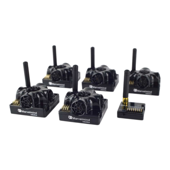
Page 6: Basics Of The System
3. Basics of the system What’s in the box Starter Set: 4xStationary beacons 1xMobile beacon (aka “hedgehog”) 1xModem/Router * Exact appearance may wary depending on the Hardware version. Characteristics are kept the same or better unless specially noted... -
Page 7: Indoor Gps Architecture
Indoor GPS architecture Marvelmind Indoor Navigation System provides high-precision (± 2 cm) indoor coordinates for autonomous robots and systems (“indoor GPS”). Brief description of the key elements of the system is given on scheme below:... -
Page 8: Indoor "Gps" System - Close-Up And Internal View
Indoor “GPS” system – close-up and internal view LiPol 3.7V 1000mAh... -
Page 9: System Elements
System elements 3.4.1 Stationary beacons Shall be mounted on walls and ceilings – usually, above the robot and ultrasonic sensors facing down – to provide the most robust unobstructed coverage of ultrasonic signal to robot. However, for automatic landing and indoor navigation of copters, for example, it is recommended to place beacons on the floor/ground and install the mobile beacon horizontally downwards looking on the belly of the copter Position for the beacons and angles of... -
Page 10: Mobile Beacon ("Hedgehog")
(virtual UART). More interfaces: http://www.marvelmind.com/#Interfaces Data from the beacon is sent in a streaming format identical that of GPS (NMEA 0183) There are 433MHz and 915MHz versions available. Proprietary radio protocol is used for communication and synchronization The “hedgehog” has been successfully integrated with Windows PC, Linux machines, Raspberry Pi, Arduino boards, Intel boards, etc: http://www.marvelmind.com/#Interfaces... -
Page 11: Modem/Router
3.4.3 Modem/router The central controller of the system. It must be powered all the time, when the Navigation System works. It is recommended to use active USB hub for that purpose or even a regular USB power supply for cellular phones. A USB power bank can be used too Modem is also used to setup the system, monitor it, interact with the Dashboard... -
Page 12: Charging Beacons And Other Details
3.4.4 Charging beacons and other details − The Beacon has 5 sensors (transducers) RX1, RX2, RX3, RX4, RX5 − DIP switch modes: 1) Power = OFF, DFU = OFF: charging is possible; beacon is disconnected from internal battery. This mode is recommended, if you want to keep the battery fully charged for a long time and store the beacon on the shelf 2) Power = ON, DFU = OFF: normal working mode for beacon. -
Page 13: Setting Up The System
4. Setting up the system The very first setup routine of your device The routine below describes the very first setup of the system. If you have done that already, please, jump to the chapter Using the system after the very first setup below. -
Page 14: Setup Software (Dashboard)
Setup software (Dashboard) 4.2.1 After charging boards download the latest stable software package from http://www.marvelmind.com/#Download 4.2.2 Select the SW version of the portable or distribution and unzip 4.2.3 Run the Dashboard and update the SW for all beacons and modem using Dashboard =>... - Page 15 4.2.7 Write down and use later the beacon’s address or change the addressed to your convenience as shown here 4.2.8 Press RESET button on your beacons and modem after programming 4.2.9 After programming devices with the latest software, modem and beacons are ready for use. Place stationary beacons on the walls vertically in such a way that optimal ultrasonic coverage is provided.
- Page 16 4.2.16 Now you can check the height position of the beacons, RSSI, radio channel, threshold etc. on the panel in the right corner of the Dashboard 4.2.17 Notice, that there are 99 beacon’s addresses available. If you don’t see some of your connected beacons on the map, scroll it so you will be able to find their addresses 4.2.18 Also double click on the device to go into sleeping mode and double clicking to wake up 4.2.19 The map will form automatically and zoom in automatically...
- Page 17 If you see in the table some empty cells or marked yellow/red, it is an indication that distances between some beacons are measured inconsistently or not measured at all. Try to check what the problems with those beacons are. Try to re-position them, because, usually, there is an obstruction of some sort in the between the beacons.
- Page 18 4.2.23 If you see on the devices’ panel beacon colored orange, it means some settings between beacons are different, for example: some sensors are off or some ultrasonic or radio settings are different. You can change the settings for sensors manually by clicking on the panel in the right corner of the dashboard and make grey cells green to turn on sensor.
-
Page 19: Using The System After The Very First Setup
Using the system after the very first setup 4.3.1 If you had setup the drivers, built and froze the map and hadn’t moved stationary beacons, in order to start using the system again, you simply have to power up the modem. The map is stored inside the modem and the system will be ready to handle your mobile beacons in 5 seconds after that More help you can find here:... -
Page 20: Dfu Programming
Download the latest SW package, unpack it and select the proper version of the SW – for your HW and for your frequency variant. Remember, that for DFU programming you shall use DFU SW – not HEX SW 4.4.3 Download: http://www.marvelmind.com/downloads/Software.zip 4.4.4 Use DFU programmer and upload DFU SW into beacon: Install DFU driver http://www2.st.com/content/st_com/en/products/development-tools/software- development-tools/stm32-software-development-tools/stm32-programmers/stsw- stm32080.html... - Page 21 Check SW on the beacon afterwards Everything should be OK with the SW now. DFU programming is completely finished 4.4.5 Upload the regular beacon’s HEX SW from http://www.marvelmind.com/#Download to make sure that the latest set of SW is used 4.4.6...
- Page 22 4.4.8 If you have experienced difficulties in DFU programming please check and do the following : Change your operation system (from Windows10 to Windows7 and vice versa) Install other DfuSe version (Install DfuSe SW 3.04 (or 3.0.3 or 3.0.5) - whatever works the best for your Windows) Check if the DIP switch is in correct position...
-
Page 23: Interfaces
Knows position of every mobile beacon in the system One can get data from mobile beacons and from the modem at the same time, if need to do so. List of supported interfaces is shown below: More on the interfaces can be found on the link: http://marvelmind.com/#Interfaces... -
Page 24: Beacon Hw V4.9 External Interface 4X4 Pinout
Beacon HW v4.9 external interface 4x4 pinout... -
Page 25: Modem Hw V4.9 External Interface Pinout
Modem HW v4.9 external interface pinout... -
Page 26: Advanced System Settings And Optimization
6. Advanced system settings and optimization Start using advanced settings only when you know what you are doing. If you ran into troubles, connect beacon/modem to PC via USB and use Default button. You will uploads “factory settings” to the board while keeping the device address untacked. Using oscilloscopes 6.1.1 Monitor ultrasonic signal from one beacon to another... -
Page 27: Proper Ultrasonic Signal Detection
Rotors of drones/copters Marvelmind Indoor Navigation System uses proprietary 31kHz frequency for ultrasonic signal and employs additional filtering to combat external noise. And it makes the system rather immune against “usual suspects”. However, if the external noise is too strong;... -
Page 28: Using Hedgehog.log File
Using hedgehog.log file – System automatically records all measured positions in hedgehog.log file that is stored in the same folder as the Dashboard.exe file... -
Page 29: Important Aspects And Hints
Important aspects and hints The single most important requirement for the system to work well is to have proper ultrasonic coverage Each sensor has an ultrasonic beam of ~90 degrees. Outside of that range the emitting power and sensitivity drops quite rapidly. From the left, right, or back sides of the ultrasonic sensor the signal is received highly attenuated. -
Page 30: Deep Hints
Deep hints Avoid placing beacons on long sound conducting objects 3. This is a very rare case, but may happen in some special circumstances 4. The best practice is to place beacons (stationary and mobile) in such places that would not result in transferring ultrasound energy from the beacon’s board/case directly to place it is attached via other medium than air. -
Page 31: Powering Beacons
Powering beacons Modes of operations: 1. Stationary beacons are powered from a clean source of +5V USB 2. Mobile beacon is powered from a clean source of +5V USB from a robot 3. Operations based on internal LiPol 3.7V 1000 mAh cell Typical power consumption in deep sleep mode is 50uA that gives ~2y shelf time with a regular 1000mAh battery. -
Page 32: Different Colors In The Dashboard Menu
Different colors in the Dashboard menu To be added in the future Manual releases Ultrasonic coverage To be added in the future Manual releases Submaps To be added in the future Manual releases... -
Page 33: Frequently Asked Questions
Frequently Asked Questions http://www.marvelmind.com/forum/viewforum.php?f=2 8. Contacts For more support, you may send us your questions to info@marvelmind.com. We will guide and advise you...
Need help?
Do you have a question about the Indoor Navigation System and is the answer not in the manual?
Questions and answers