Table of Contents
Advertisement
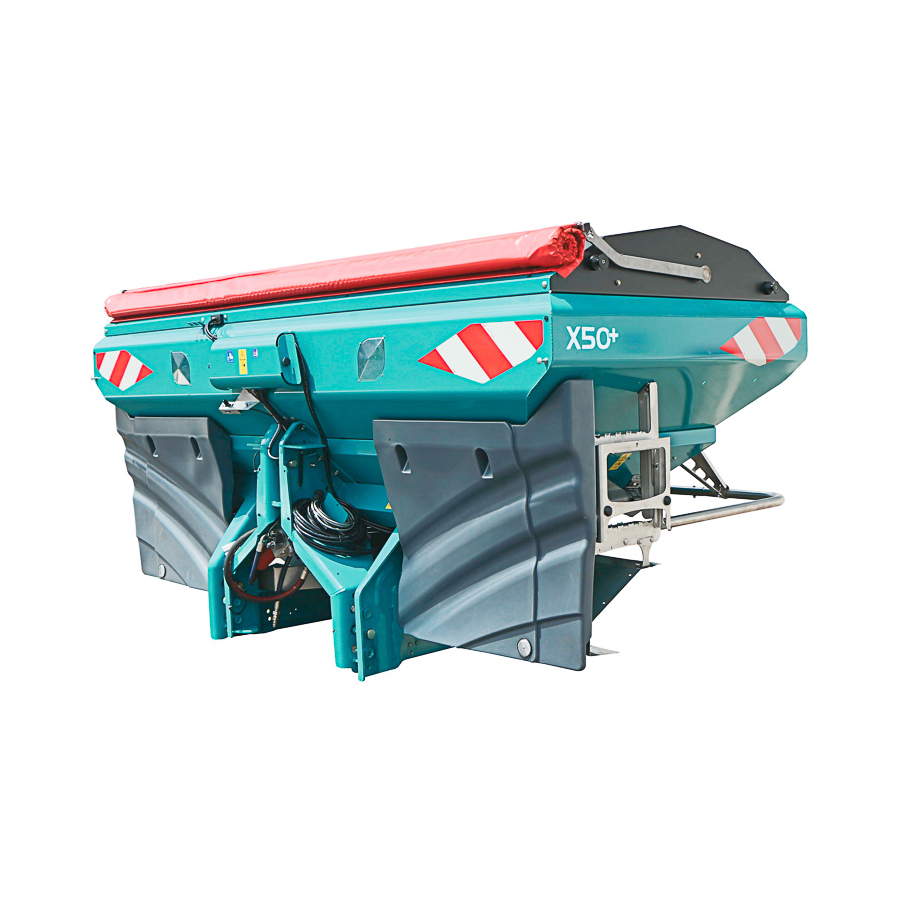
2400 - 3200 - 4000
Original Instructions
Orginalinstruktioner
5
+
PLEASE READ CAREFULLY BEFORE USING THE MACHINE
VÄNLIGEN LÄS NOGGRANT INNAN ANVÄNDNING AV MASKINEN
Réf: 400957 - 01 EN-SE/ FD
Les Portes de Bretagne
P.A. de la Gaultière – 35220 CHATEAUBOURG France
Tél :(33)02-99-00-84-84 · Fax : (33)02-99-62-39-38
Site Internet : www.sulky-burel.com
E-Mail : info@sulky-burel.com
Adresse postale
SULKY-BUREL – CS 20005 – 35538 NOYAL SUR VILAINE CEDEX France
Advertisement
Table of Contents

Related Manuals for Sulky X50+ 2400


Summary of Contents for Sulky X50+ 2400
- Page 1 Réf: 400957 - 01 EN-SE/ FD Les Portes de Bretagne P.A. de la Gaultière – 35220 CHATEAUBOURG France Tél :(33)02-99-00-84-84 · Fax : (33)02-99-62-39-38 Site Internet : www.sulky-burel.com E-Mail : info@sulky-burel.com Adresse postale SULKY-BUREL – CS 20005 – 35538 NOYAL SUR VILAINE CEDEX France...
- Page 3 Dear customer / Kära kund Dear Customer, Thank you for trusting our equipment and choosing the spreader. To ensure correct operation, and to get the most out of your spreader, we recommend that you read these instructions carefully. Please do not hesitate to give us your suggestions and comments based on your experience.
- Page 4 In accordance with Appendix 2, Section 1, Point A of the European Machinery Directive 2006/42/EC. I enlighet med Bilaga 2, Avsnitt 1, Punkt A i det europeiska maskindirektivet 2006/42/EC Declaration of Conformity Försäkran om överensstämmelse SULKY-BUREL ’ ANUFACTURER S NAME AND ADDRESS DE LA AULTIÈRE...
- Page 5 Safety regulations Risk of damage Operating tip Caution Payload should Risk of accident to the machine not be exceeded Risk of damage Danger Moving parts, Fall hazard. Do not to the machine keep away climb on the machine. Consult the instruction leafl et These symbols are used in these instructions every time recommendations are provided concerning your safety, the safety of others or the correct operation of the machine.
- Page 6 machine or recommended by the manufacturer. circuit, ensure that the tractor-side and machine-side 6 - Before operating on the electric circuit, disconnect 2 - Power take-off and universal drive shaft guards circuits are not pressurized. the power source. must always be fi tted and in good condition. 4 - The user of the machine is strongly recommended 7 - Protective devices likely to be exposed to wear 3 - Ensure that the tubes of the universal drive shafts...
- Page 7 Säkerhetsföreskrifter Risk för skada på Arbetstips Varning Lastförmågan bör inte Risk för olycka maskinen överskridas Fara Rörliga delar, Fallrisk. Klättra inte Risk för skador håll avstånd upp på maskinen. på maskinen Konsultera bruksanvisningen Dessa symboler används i dessa anvisningar varje gång rekommendationer är tillgänglig om din säkerhet, säkerheten för andra eller korrekt användning av maskinen.
- Page 8 6 - Se alltid till att universella drivaxlar är monterade 6 - När en läcka har hittats bör alla nödvändiga och fastlåsta på rätt sätt. åtgärder vidtas för att undvika olyckor. 7 - Se alltid till att de universella drivaxlarnas skydd 7 - Trycksatt vätska, särskilt hydraulkretsens olja kan är immobiliserade i rotation med hjälp av de speciellt orsaka allvarliga skador om det kommer i kontakt...
-
Page 9: Table Of Contents
English CONTENTS Pages START-UP 10-11 • A 22-33 • F Control connections 10-11 • B Handling 34-35 • G Loading 12-13 • C Tractor control 34-35 • H Emptying 16-17 • D Hitching gear 18-21 • E Drive assembly Pages SETTINGS 36-43 •... - Page 11 Svenska INNEHÅLL Sidor UPPSTART 10-11 • A Användning 22-33 • F Anslutningar av kontroller 10-11 • B Hantering 34-35 • G Påfyllning 14-15 • C Traktorkontroll 34-35 • H Tömning 16-17 • D Påkoppling 18-21 • E Drivaggregat/ Transmission Sidor INSTÄLLNINGAR 36-43 •...
- Page 12 Start-up / Uppstart Var försiktig när du lyfter Take care when lifting the maskinen; Kontrollera machine; check that there is att ingen är i den direkta no-one around. omgivningen. Remove all fi xtures or Ta bort alla fästanordningar guards installed on the eller skydd som varit machine, for transport nödvändiga vid...
- Page 13 Start-up / Uppstart This device should be used as follows: - Check that your equipment is complete on delivery. - With the machine hitched to the tractor. - Make sure that there are no foreign bodies in the hopper. - The machine should be placed on level ground, for •...
- Page 14 Start-up M1mini = M2 x (c + d) - P1 x b + (0,2 x P x b) =......Kg a + b = M1 x (a + b) + P1 x b - M2 x (c + d) =......Kg = M1 + P + M2 =......Kg = Pc - P1c =......Kg...
-
Page 15: Tractor Control
Start-up Tractor control - To be checked : • The total authorised weight. • The permitted weight per axle. • The authorised support weight on the tractor’s linkage. • The permissible load capacity for the tyres fitted to the tractor. •... - Page 16 Uppstart M1mini = M2 x (c + d) - P1 x b + (0,2 x P x b) =......Kg a + b = M1 x (a + b) + P1 x b - M2 x (c + d) =......Kg = M1 + P + M2 =......Kg = Pc - P1c =......Kg...
- Page 17 Uppstart TraktorKontroll - Att kontrollera : • Den totala tillåtna vikten. • Den tillåtna vikten per hjulaxel. • Den godkända stödvikten på traktorns kopplingspunkt. • Den tillåtna lastkapaciteten för däcken monterade på traktorn. • Är tillåten kopplingsbelastning tillräcklig? All information finns i traktorns registreringsbevis eller på traktorns maskinskylt och i traktormanualen AD DU BÖR KÄNNA TILL Traktorns egenvikt Kontrollera traktorns bruksanvisning eller registre-...
- Page 18 Start-up / Uppstart Maximum payload Maxbelastning 4000 kg 4000 kg. Koppla endast bort Only unhitch the machine if maskinen om the hopper is empty matartratten är tom...
-
Page 19: D Hitching Gear
Start-up / Uppstart Hitching gear The machine is fitted with a category II three-point clevis hitch. • The working position of the machine is horizontal and (A) 70 cm above the ground. - Use the level indicator to adjust the spreader perpendicular. - Page 20 Start-up / Uppstart L mini L maxi 1/2 X 35° 35° Ensure that your PTO drive Se till att din assembly is guarded, in kraftöverföringsenheten good condition and complies är skyddad, i gott skick with current standards. och överensstämmer med The guarantee will not gällande standarder.
-
Page 21: E Drive Assembly
Start-up / Uppstart Drive assembly - Allow 3 cm slack at each end The standard speed is 540 rpm, except for the borders of the - Shorten the inner and outer protective tubes to the field and certain types of fertilizer. (see tables) same length. - Page 22 Start-up / Uppstart 1 mm Assembly should take place Montering ska ske med with the hopper empty and matartratten tom och chocks should be placed eventuellt kan kilar behövas under the machine during under maskinen. this time.
- Page 23 Start-up / Uppstart Fitting : - Grease the machine’s transmission input shaft before fitting the PTO. - It is essential that the gap of 1 mm is adhered to. - Tighten the screw and the nut - Reduce the length of the chain that holds the shaft guard Montering : - Smörj maskinens kraftöverföringsaxeln för...
- Page 24 Start-up / Uppstart Montering av kontroller/ Fitting the controls: see styrenheter: se bifogade enclosed instructions instruktioner Caution: oil under pressure. Varning: Trycksatt olja. Store the controls or the Förvara kontrollerna hydraulic hoses in the eller hydraulslangarna specially-provided areas on på avsedda områden på the machine.
- Page 25 Start-up / Uppstart Control connections - The red tap for the LH flap - The blue tap for the RH flap a) Cable control ITTED ON ONE SINGLE ACTING SPOOL VALVE - Mount the control support on the tractor The shutters are opened by a single action. The shutters can be controlled independently of each other by using the - To do this, lower the machine, line up the control unit two taps fitted on the outside of the cab.
- Page 26 Start-up / Uppstart Fitting the controls: see Montering av kontroller/ enclosed instructions styrenheter: se bifogad Caution: oil under pressure. bruksanvisning. Store the controls or the Varning: trycksatt olja. hydraulic hoses in the Förvara kontrollerna specially-provided areas on eller hydraulslangarna the machine. på...
- Page 27 Start-up / Uppstart ITTED ON TWO DOUBLE ACTING SPOOL VALVES The shutters are opened using two double acting spool To spread on both sides: valves. - Activate the tractor’s double acting spool valve Pilot valves prevent the shutters from opening inadvertently during transport.
- Page 28 Start-up / Uppstart...
- Page 29 Start-up / Uppstart c) STOP&GO, VISION electrical control Use of the system requires specific adjustments. To use your machine correctly, it is necessary to programme SSEMBLY This control may be placed on the side of the VISION WPB the correct settings. console.
- Page 30 Start-up / Uppstart...
- Page 31 Start-up / Uppstart To open just one chute (right or left) simply press the button corresponding to the desired side. For example the two chutes are closed For example the two chutes are open You want to open just one chute You want to close just one chute - for the left, press here - for the left, press here...
- Page 32 Start-up / Uppstart...
- Page 33 Start-up / Uppstart d) ECONOV, VISION electrical control Use of the system requires specific adjustments. Assembly To use your machine correctly, it is necessary to programme This control may be positioned on the side of the VISION the correct settings. WPB console.
- Page 34 Start-up / Uppstart...
- Page 35 Start-up / Uppstart To open just one chute (right or left) simply press the button e) ISOBUS electrical control corresponding to the desired side. - Consult the ISOBUS operator’s manual For example the two chutes are closed - The ISOBUS standard allows the user to connect ISOBUS You want to open just one chute machines onto the QUARTZ console.
- Page 36 Start-up / Uppstart Mini 40 cm mini Do not stand in the hopper Stå inte i matartratten då den är while in operation! igång!
- Page 37 Start-up / Uppstart Loading Emptying a) Sieves The machine must be switched off. - Check that there are no foreign objects in the hopper - Remove the spreading discs before loading. - Use the calibration test chute on the linkage - Close the sieves.
- Page 38 Settings / Inställningar Kg/ha A test run is strongly Det är starkt recommended to obtain an rekommenderat att du accurate setting. The setting genomför ett fl ödestest charts are provided as an för att uppnå god indication only. inställningsprecision. Use the slide calculator to Inställningstabellerna determine your setting.
-
Page 39: Settings
Settings / Inställningar Setting the flow rate ELECTING THE INDEX ACCORDING TO YOUR RATE HA CAN BE DONE THREE WAYS For a machine fitted with VISION or ISOBUS electronics, please refer to the VISION or ISOBUS operator’s manual. Using the flow charts supplied with the manual : choose the fertilizer which corresponds most closely to For a machine fitted with manual application rate adjust- your product, read off the theoretical setting and carry... - Page 40 Settings / Inställningar ... m ... m 12 m 41,7 m ..............15 m 33,4 m ..............18 m 27,8 m ..............20 m 25,0 m ..............21 m 23,8 m ..............24 m 20,8 m ..............27 m 18,5 m ..............
- Page 41 Settings / Inställningar Rate tests Setting with the charts - Position the marker at the setting corresponding to your The test is to be carried out before each spreading operation fertilizer as indicated in the enclosed tables. so that the correct quantity per hectare is applied. - Check the mark by performing a calibration test over a The variable nature of fertilizer is such that this process is distance...
- Page 42 Settings / Inställningar RÉGLAGE DU DÉBIT SUR VOTRE DISTRIBUTEUR D’ENGRAIS Par sécurité avant les opérations , arrêter la prise de force Distance d’essai Mise en place Lecture du poids d’engrais recueilli Si votre largeur votre distance d’essai de travail est : à...
- Page 43 Settings / Inställningar Setting with the slide-rule - On the back of the slide-rule, set the red bar along the top section to the weight obtained. Whatever the type of fertilizer used, the slide-rule will enable you to determine the setting for the shutter openings for the - Choose the curve relating to your quantity per required rate, with a single test without using the charts.
- Page 44 Settings / Inställningar Poids obtenu lors de l'essai (en kg) MODE D'EMPLOI : Alignez la barre rouge sur le poids d'engrais obtenu (zone rouge). Ensuite, choisissez dans la zone bleue la courbe qui correspond au débit/ha recherché. Suivez cette courbe. Dès que vous croisez la barre rouge, vous Repère...
- Page 45 Settings / Inställningar Rate Modulation (example -10% at 200Kg/ha) Your machine is set for 200 Kg/ha at mark 25 - Multiply this rate by 0,9 (200 x 0,9 = 180 Kg/ha). - Transfert this value on to the required rate. In this case : mark 22 150 kg...
- Page 46 Settings / Inställningar For correct spreading, the För bra spridning är det discs and the ejector blades absolut nödvändigt att need to be kept in good spridarskivor och –blad condition. hålls i gott skick.
-
Page 47: B Setting The Width
Settings / Inställningar Setting the width It can be blocked off using the handle For a machine fitted with VISION or ISOBUS electronics, For an ECONOV machine, the management of the feeder please refer to the VISION or ISOBUS operator’s manual. spouts is by electric cylinders which are driven from the VISION CAN console. - Page 48 Settings / Inställningar 3,15 10cm...
- Page 49 Settings / Inställningar b) Fertilizer characteristics The structure and the shape of the fertilizer are very impor- tant to obtain a wide sowing band, and it is recommended to select the most suitable product. Using the granulometer Open the cover. Fill the left-hand compartment of the granulometer with fertilizer then close the cover.
- Page 50 Settings / Inställningar...
- Page 51 Settings / Inställningar The compartments are sized as follows: If the spreader is not used to its full capacity A = < 2mm (24 m with a 24-36m set of blades, for example), the percent- B = 2,5 to 2mm age of fertilizer over 2.5 mm may be reduced.
- Page 52 Settings / Inställningar 70 cm 540 obr./min. + 15% For correct spreading, the För bra spridning är det discs and the ejector blades absolut nödvändigt att need to be kept in good spridarskivor och –blad condition. hålls i gott skick.
- Page 53 Settings / Inställningar c) Settings The + sign indicates that the PTO speed must be in- creased by 15%. 540 620 rpm ETTING WITH THE CHARTS The - sign indicates that the PTO speed should be By consulting the charts, search for the fertilizer which corre- reduced by 15%.
- Page 54 Settings / Inställningar...
-
Page 55: C Checking The Width
Settings / Inställningar Checking the width To check the width, an overlap self-check kit is available as an option. Setting with overlap check list The critical spreading zone corresponds to the overlap area between an outward and return pass. The kit enables this zone to be checked to enable you to adjust the setting. - Page 56 Settings / Inställningar 1/2 L 1,50m 3,00m 4,50m 6,00m 1,50m 3,70m 5,60m 7,50m 1,50m 4,00m 6,00m 8,00m 1,60m 4,50m 6,70m 9,00m 1,70m 5,00m 7,50m 10,00m 1,80m 5,20m 7,80m 10,50m 2,00m 6,00m 9,00m 12,00m 2,20m 6,70m 10,10m 13,50m 2,50m 7,00m 10,50m 14,00m 2,80m 8,00m...
- Page 57 Settings / Inställningar OSITIONING THE TRAYS Make sure that their position is correct in accordance with your working width (L) and your machine (see table 2). - Place them on level ground. LACERING AV TRÅGEN Se till att deras placering är korrekt i förhållande till arbetsbredden (L) och din maskin (se tabell 2) - Placera dem på...
- Page 58 Settings / Inställningar...
- Page 59 Settings / Inställningar HE TEST ITSELF The distance required for the test is around 120 m. Start up the spreader about 30 metres before the trays. Only stop spreading after passing the trays by at least 50 m. Make another pass corresponding to your working width.
- Page 60 Settings / Inställningar + 10% + 25% -2,5 + 50% + 10% + 25% +2,5 + 50%...
- Page 61 Settings / Inställningar Not enough fertiliser in the overlap: EST ANALYSIS Identical amount in all 4 tubes : - Increase the chute setting depending on the underdose measured in the overlap by following the examples or Good overlap which corresponds to a good spread. this formula : Chute adjustment = (1- ( amount in tube B) ) x 10 Too much fertiliser in the overlap :...
- Page 62 Settings / Inställningar - 30%...
- Page 63 Settings / Inställningar Special situation : HE TUBES FORM A DOME - You have to try to obtain the same quantity in the 2 extre- me tubes. - For this, continue as before, by adjusting depending on the difference in quantities obtained. - If the difference is more or equal to 30% you must reduce the working width as fertiliser physical limits are reached.
- Page 64 Settings / Inställningar Stop the PTO before Gör inställningarna efter att adjusting. kraftuttaget har stannat.
- Page 65 Settings / Inställningar a) Full width spreading In principle, a double-disc machine spreads in a half circle. The fertilizer is projected from the rear of the machine. The end of spreading on the outward pass should be offset in relation to the start of spreading on the return pass as illustrated.
- Page 66 Settings / Inställningar Stop the PTO before Gör inställningarna efter att adjusting. kraftuttaget har stannat.
- Page 67 Settings / Inställningar b) Top dressing c) Spreading on steep slopes - Set the lower linkage point in the most favourable - When using your spreader on steeply sloping fields, place position. the devider in the centre of the chute. Horizontal position for spreading on bare ground.
- Page 68 Settings / Inställningar /L=L ET OF VANES RIBORD VANE IGHT ORKING WIDTH ACHIEVED /L=V LADSATS RIBORDBLAD ÖGER ÄNSTER TFÖRD ARBETSBREDD EVTR / EVTL 18 18 m EV 18 – 28 EVTR / EVTL 28 from 19 to 28 m/ från 19 till 28 m EVTR / EVTL 24 24 m EV 24 –...
-
Page 69: D Border Setting With The Tribord
Settings / Inställningar Border setting with the tribord Right border spreading, optimised for the environ- ment, red diode flashes. As standard the machine is fitted with TRIBORD on the right- hand side. With the ISOBUS control KIT the TRIBORD may be Note : added as an option for the left-hand side;... - Page 70 Settings / Inställningar < 32 m ≥ 32 m -20 % -10 % -10 % 540 rpm -15 % -15 % -15 % -15 % < 32 m > 32 m -10 % 540 rpm 540 rpm 540 rpm...
- Page 71 Settings / Inställningar Unless the settings table for the fertilizer used indicates ORDER SPREADING ADJUSTMENT Your fertiliser spreader can be adjusted to two diff erent modes for border spreading to optimize results. Full width spreading : (green diode illuminated) PTO speed at 540 rpm and your application rate at 100%. in which case reduce the PTO speed by 10% (485 rpm).
- Page 72 Settings / Inställningar < 32 m ≥ 32 m -20 % -10 % -10 % 540 rpm -15 % -15 % -15 % -15 % < 32 m > 32 m 540 rpm 540 rpm 540 rpm -10 %...
- Page 73 Settings / Inställningar And if the settings table for the fertilizer used indicates Yield border speading: (yellow diode lit up) If the working width is less than 32 m : - activate the Tribord system and reduce the PTO speed by 10% (485 rpm).
- Page 74 Settings / Inställningar...
-
Page 75: Environmental Border Optimisation With The Tribord
Settings / Inställningar Environmental border optimisation with the tribord ERFORMING THE TEST Place the trays as shown in the drawing and refer to table for the correct inter-tray distances. Start spreading 30 metres before the trays. Only stop spreading once 50 m after the trays. - Page 76 Settings / Inställningar 100% < 15% x and / och 100% > 50% x -10 % 100% > 15% x -10 % 100% < 15% x and / och 100% < 50% x +10 %...
- Page 77 Settings / Inställningar - If it is still too high, reduce the rate on the border side by EST ANALYSIS 10%. NB : (see section on “Rate modulation”) Border spreading cannot be set unless normal in-field sprea- ding has been set beforehand Not enough fertiliser on the border The amount in trays 2, 3 and 4 represents less than 50% Good spreading for environmental borders :...
- Page 78 Settings / Inställningar 00 1 -20 % -10 %...
- Page 79 Settings / Inställningar Border setting with the ecobord vane For machines that are not equipped with the tribord . Border spreading with the environmental optimisation ecobord. Border spreading system following the right hand tramline. - Fit the ecobord on the long spreading vane. - Reduce the rate by 20% - PTO: -10% reduction in engine speed by around –10%...
- Page 80 Maintenance / Underhåll The lifetime and the good Maskinens livslängd och working order of your funktion beror i hög grad machine depend essentially på hur den används och on the attention paid to it. underhålls. Carry out the spraying Utför sprayning i en operation in a well- välventilerad lokal eller ventilated room, or...
-
Page 81: A Washing
Maintenance / Underhåll Safety b) After each spreading application Any intervention on the spreader must be carried out by -Wash your spreader with non-pressurized water after someone familiar with the operation manual. each use. - For washing and maintenance operations, always wear protecting gloves and glasses. - Page 82 Maintenance / Underhåll 16 h Long, trouble-free service Maskinens livslängd och depends essentially on the funktion beror i hög grad care you take with your på hur den används och machine. underhålls. Greased right-angled Infettade vinkeldrev är gearbox (maintenance-free). underhållsfria.
-
Page 83: Lubrication
Maintenance / Underhåll Lubrication a) Power take-off Follow the maintenance instructions provided with the power take-off. See diagram for lubrication points. b) Mechanism - Grease the moving parts with a brush before storage. - Grease points every 8 hours. c) Angle take-off Angle take-offs are maintenance-free except for outside cleaning. - Page 84 Maintenance / Underhåll Excessive vane wear aff ects Överdriven och onödig the spreading nötning av bladet inverkar quality. på spridningens kvalitet. When ripples appear in the Byt ut bladet om det bildats bottom of the vanes, they vågor på dess kanter need to be replaced.
-
Page 85: C Checks
Maintenance / Underhåll Checks HEN REPLACING VANES a) Checks - Make sure you have the right set, by checking the markings on the top of the vane. - Within the first operating hours, check the tightness of the main nuts: - Check the vane fitting direction in relation to the disc Spreading vanes rotating direction. - Page 86 Maintenance / Underhåll 10/2012 16 mm 10/2012 6 mm The machines are factory- Maskinerna har kalibrerats calibrated and inspected. och kontrollerats på Only intervene if the fl ow fabriken. rate irregularity is Gör inga ingrepp om signifi cant. det inte uppstår stor oregelbundenhet i fl ödet.
-
Page 87: D Calibration Check
Maintenance / Underhåll Calibration check 10/2012 The space between the end of the regulator and the a) Raste calibration check shutter should be 6 mm, to adjust it, turn the screw (this distance need not be exactly 6 mm, what is important is - If you notice a difference in rate between the right-hand that the measurement is the same for both regulators, e.g.: and left-hand side whilst spreading, check the following... - Page 88 Maintenance / Underhåll Do not adjust the Gör inga ingrepp i spridaren distributor unless the om inte traktorns motor står tractor is switched off with stilla the ignition key removed.
- Page 89 Maintenance / Underhåll b) Width calibration check HUTTER CALIBRATION - Having calibrated the agitators, if a difference in the rate PREADING CHUTES between one side and the other is still noticed, proceed as follows : - If you observe a significant lack of symmetry in spreading in relation to the centre of the machine, please Set the rate lever to 49.
-
Page 90: Fitting The Accessories
Fitting the accessories / Montering av tillbehör Follow the fi tting Följ instructions. monteringsinstruktionerna. Do not adjust the Gör inga ingrepp i spridaren distributor unless the om inte traktorns motor står tractor is switched off with stilla. the ignition key removed. -
Page 91: A Anti-Compaction Baffe
Fitting the accessories / Montering av tillbehör Anti-compaction baffle PTIONAL FOR Ammonium sulphate Damp powdery fertilizers Ray Grass, etc. ITTING - Tractor engine switched off. - Open the sieves. - Position the baffle against the bottom side of the sieve and centre it in relation to the bottom of the hopper. - Page 92 Fitting the accessories / Montering av tillbehör Follow the fi tting Följ instructions. monteringsinstruktionerna. Do not adjust the Gör inga ingrepp i spridaren distributor unless the om inte traktorns motor står tractor is switched off with stilla. the ignition key removed.
-
Page 93: B Hopper Cover
Fitting the accessories / Montering av tillbehör Hopper cover See the fitting instructions supplied with the kit. Presenning Se medföljande monteringsinstruktioner. - Page 94 Fitting the accessories / Montering av tillbehör Follow the fitting Följ instructions. monteringsinstruktionerna. Do not adjust the Gör inga ingrepp i spridaren distributor unless the om inte traktorns motor står tractor is switched off with stilla the ignition key removed.
-
Page 95: C W Vision Control Kit
Fitting the accessories / Montering av tillbehör W VISION control kit Electronic device for rate proportional to forward speed and modulation. See the user instructions supplied. W ISOBUS control kit Electronic device enabling use in compliance with the ISOBUS standard. “Télé-space”... - Page 96 Fitting the accessories / Montering av tillbehör...
-
Page 97: G Mud Guard
Fitting the accessories / Montering av tillbehör Parking wheel Hopper extension - Fit as shown in the diagram. - See the instructions supplied with the kit. HE WHEELS HAVE TWO POSITIONS 1000 rpm PTO kit Storage position (as shown in the photo) Spreading positions To use the X50 with a 1000 rpm PTO: - Use the wheels only when the hopper is empty. - Page 98 Fitting the accessories / Montering av tillbehör...
-
Page 99: Fitting The Supports
Fitting the accessories / Montering av tillbehör Fitting the supports (option) - The “tilting and parking supports” KIT is available as an option. To mount the kit, fit the supports and place the sup- ports in the working position. They will help you to hitch the machine up to the tractor more easily. - Page 100 Specifi cations / Specifi kation Warning notices relating to Maskinen har ett safety are affi xed to your fl ertal påklistrade machine. varningsmeddelanden med Their aim is to contribute to viktig säkerhetsinformation. your safety and to the safety De är till för att öka of others.
- Page 101 Specifications / Specifikation Identification Please note the following information when you take delive- ry of your machine : Machine number: Machine type : Accessories: Technical Specifications INIMUM LOADING ISTANCE BETWEEN THE OADING EVEL VERALL HEIGHT WITH THE LINKAGE PIN AND THE WIDTH CAPACITY WIDTH...
Need help?
Do you have a question about the X50+ 2400 and is the answer not in the manual?
Questions and answers