Table of Contents
Advertisement
Quick Links
Advertisement
Table of Contents

Subscribe to Our Youtube Channel
Related Manuals for WATERGUARD Smart Stop 5648191


Summary of Contents for WATERGUARD Smart Stop 5648191
- Page 1 INSTALLATION INSTRUCTIONS USER MANUAL SMART STOP Version May 25, 2020...
- Page 2 This information is valid for these Smart Stop types: 1 valve 1/2” ART NO 5648191 1 valve 3/4” ART NO 5648193 1 valve 1/2” NC ART NO 5648195 1 valve 3/4” NC ART NO 5648197 INSTALLATION INSTRUCTIONS / USER MANUAL...
-
Page 3: Included Components
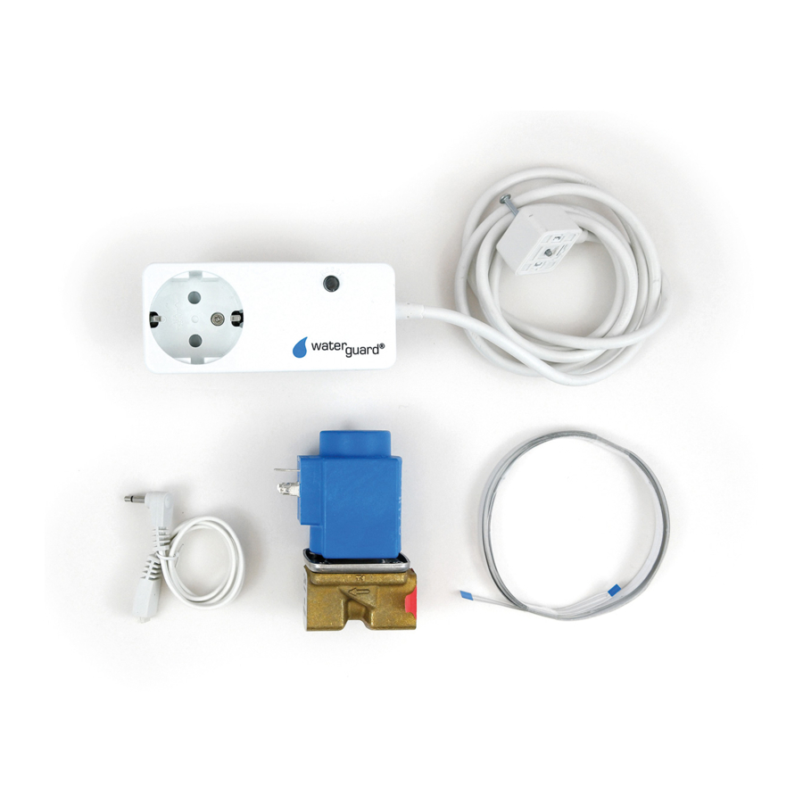
Included components 1 CENTRAL UNIT WTG-38A (ART NO 5648329) The unit doubles as central unit and control panel. 2 SOLENOID VALVE (1 OR 2 PCS.) Danfoss® solenoid valve comes in 1/2” to 2” dimensions. A3 WTG-36C WIRELESS VALVE CONTROL (NC) Activates the solenoid valve when a leak is detected by the system. -
Page 4: About The System
About the system Waterguard® Smart Stop is a wireless system for stopping water leaks. It has a central unit that works together with wireless sensors and the wireless valve control. All wireless components must be connected to the wireless central unit/control panel. -
Page 5: Safety Function
NB! When exercising is performed, the voltage wil be cut in the units 230V port. This cut lasts for abt. 300 ms, and might cause connected appliances to change their operating status. Should this happen, it is not regarded a error on the valve control from Waterguard. INSTALLATION INSTRUCTIONS / USER MANUAL... - Page 6 Registrating/pairing wireless units WIRELESS UNITS Prior to assembly, the wireless units must be registred in the central unit! Connect the wireless central unit to power. Connect the wireless valve control to power, connect the solenoid valve(s)s to the valve control. Open up the wireless sensor and insert batteries, do not put back the lid.
-
Page 7: Installation Instructions
Installation instructions WIRELESS CENTRAL UNIT/CONTROL PANEL 1 The wireless central unit should be mounted in a concealed wallbox so that the enclosed power supply can be placed inside the box. This willl ensure a good looking installation and stable power supply. It can also be placed inside one of the underlaying swithces’... - Page 8 Installation instructions WIRELESS SENSOR On the floor Can lay loose on the floor below washing machine, refridgerator etc. Remove the wall bracket to let the sensors get in touch with the underlay. Insert batteries according to instructions. The loose sensor tip can be folded under the sensor before sensor is placed on the floor.
- Page 9 10 Control that the water still flows from the open tap. 11 Moisten the sensor point on the first wireless sensor. The drop in the Waterguard logo will light up red when moist i detected, and an alarm signal is being sent.
- Page 10 Principal sketch CENTRAL UNIT CENTRAL UNIT WIRELESS SENSOR WIRELESS SENSOR SENSOR TAPE SENSOR TAPE MAIN STOPCOCK MAIN STOPCOCK 230 V GROUNDED 230 V GROUNDED FILTER / SIL FILTER / SIL SOLENOID VALVE SOLENOID VALVE VALVE CONTROLLER VALVE CONTROLLER INNGANG KJØKKEN ENTRANCE ENTRANCE KITCHEN...
-
Page 11: Reset Button
User manual IN CASE OF ALARM 1 The system has two types of alarms when detecting a RESET BUTTON leak: 2 A wireless sensor detection will only be alarmed in the wireles control panel. 3 A leakage detected by the valve control’s sensor cable will be alarmed both on the valve control and on the control panel. - Page 12 User manual Battery change The enclosed sensor batteries has an expected life of approx. 5 years. We recommend a battery change after max 5 years. Sensors with weak batteries may, if placed far away, not connect with the central unit. In case of low batteries, the central unit will warn with an audio signal only.
- Page 13 Confirmed installation THE SYSTEM IS INSTALLED AND TESTED BY name Date Firm Phone Valve control is mounted Wireless sensor 1 is mounted Wireless sensor 2 is mounted Wireless sensor 3 is mounted Wireless sensor 4 is mounted Wireless sensor 5 is mounted Wireless sensor 6 is mounted Wireless sensor 7 is mounted Wireless sensor 8 is mounted...
Need help?
Do you have a question about the Smart Stop 5648191 and is the answer not in the manual?
Questions and answers