
Related Manuals for Hi-Target iBoat BS3


Summary of Contents for Hi-Target iBoat BS3
- Page 1 BS3 USV User Manual iBoat BS3 User Manual Hi-Target Surveying Instrument Co., Ltd. All Rights Reserved...
- Page 2 BS3 USV User Manual Manual Revision Revision Date Revision Level Description Aug. 2020 iBoat BS3 User Manual 1.1 Version...
-
Page 3: Preface
BS3 USV system. Experience Requirement In order to make better use of Hi-Target iBoat BS3 USV system, Hi-Target recommends that you have certain GIS knowledge and read this manual carefully. If you have any questions, please check the official website of Hi-Target: http://www.hi-target.com.cn. - Page 4 Relevant Information You can obtain this introduction by: 1. Purchasing Hi-Target products: you will find this manual in the instrument container to guide you on operating the instrument. 2. Logging onto the Hi-Target official website to download the electronic version introduction at Partners →...
-
Page 5: Table Of Contents
BS3 USV User Manual Contents Preface ........................III Hardware Connection ....................3 Overall Operation Flow .................... 6 2.1 Power on Controller .................. 6 2.2 Switch on USV ................... 6 2.3 LAN IP Setting ................... 7 2.4 Run Virtual Serial Port Software ............... 8 2.5 Setup GNSS Receiver by Hi-MAX ............. - Page 6 GNSS navigation. More sensor equipment can be loaded to perform various surveying tasks. Accurate control of iBoat BS3 makes it easy to conduct ultra-shallow and nearshore hydrographic surveying, greatly improving the monitoring efficiency and accuracy, reducing the risk of monitoring staff working on the water;...
-
Page 7: Hardware Connection
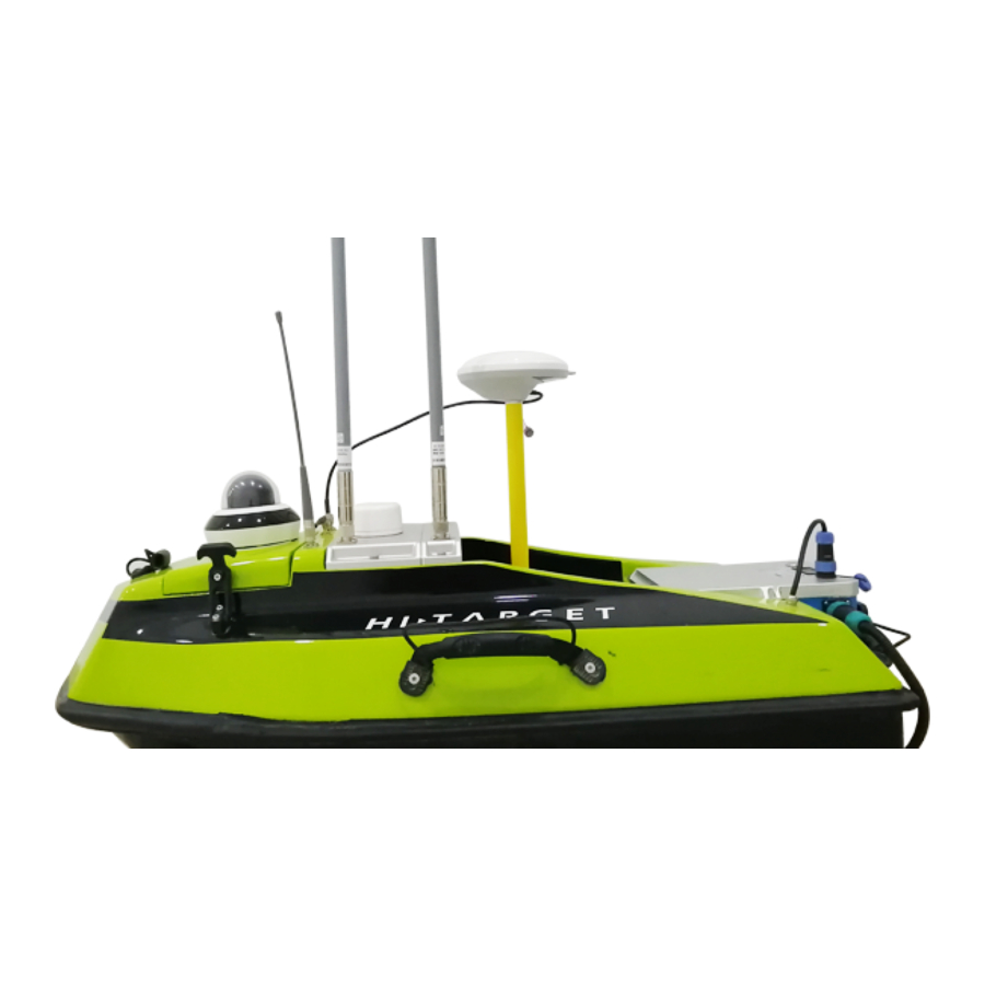
BS3 USV User Manual Hardware Connection The complete view after all things are installed well: Data Transmission Controller Antenna(5.8GHz) Antenna(2.4GHz) Differential Data Transmission Antenna Battery Module 360° PTZ Camera Charging Port ADCP Port Power Switch GNSS Antenna Figure 1-1 Complete view & antenna description Description of ashore station... - Page 8 BS3 USV User Manual Ashore Station omni-direction Antenna Working Base Remote Controller Figure 1-3 Ashore Base System Ashore Station omni-direction Antenna Figure 1-4 Wireless bridge connection The laptop and the base station (LAN Port ↔ laptop ethernet port) can be connected by a network cable, which works as a LAN cable.
- Page 9 BS3 USV User Manual Charging Port Discharging Port LAN Port POE Port Figure 1-5 Base Battery and connection Power Switch Battery Indicator Figure 1-6 Working state of the battery Power on the black battery (don’t forget it is a POE power supplier also), the screen indicates power and related information.
-
Page 10: Overall Operation Flow
BS3 USV User Manual Describing essential parts of the controller: Unlock Switch Mode Selection Propeller Controller Stick Direction Control Stick Power Button - Power Button: Click one time and long-press to power on or off the controller. - Propeller Control Stick: Push the stick up to control the USV forward. Push the stick down to control the USV backward. -
Page 11: Lan Ip Setting
BS3 USV User Manual health of the engine system. This checking step can be done on the ground before deploying it into the water. 2.3 LAN IP Setting Open the network configuration page of your laptop and set the local network IP (IPV4) to 192.168.1.88, the mask will set as 255.255.255.0 automatically. -
Page 12: Run Virtual Serial Port Software
BS3 USV User Manual Figure 2-3-2 Wi-Fi IP setting 2.4 Run Virtual Serial Port Software Run installer USR-VCOM.exe and then run the program immediately. Add a new virtual serial ports as below. Figure2-4-1 Virtual serial port configuration Three Virtual Serial Port configuration as follows: Port Function: Boat control Virtual COM: COM3(can be customized) Net Protocol: TCP Client... -
Page 13: Setup Gnss Receiver By Hi-Max
BS3 USV User Manual Port Function: GNSS connection Virtual COM: COM4(can be customized) Net Protocol: TCP Client Remote IP: 192.168.1.18 Remote Port: 8000 Port Function: ADCP connection Virtual COM: COM5(can be customized) Net Protocol: TCP Client Remote IP: 192.168.1.18 Remote Port: 9000 Figure2-4-2 Connecting status When the ports set up, The Connected will be displayed and data income increase if everything goes well. -
Page 14: New Project
BS3 USV User Manual Figure 2-5-1 Main interface of Hi-Max 2.5.1 New Project Figure 2-5-2 New project creating The project name is at the top of the project list once it had been created. -
Page 15: Serial Port Debug
BS3 USV User Manual 2.5.2 Serial Port Debug Figure 2-5-3 Serial port debug Click Connect GPS button Figure 2-5-4 GPS connecting Set the correct parameters and choose the right receiver type, click Connect. - Page 16 BS3 USV User Manual Figure 2-5-5 GPS information On the top of the window shows the expiry date of the GNSS receiver. Restart the receiver if a license is applied. Click SetRover Button. Figure 2-5-6 Rover setting Select the DataLink format. If there is the base station, choose the Built-in Radio mode. Click Setting and enter the channel number in the pop-up Radio Setting window.
- Page 17 BS3 USV User Manual Figure 2-5-6 Radio setting If use CORS, select the Built-in Wireless mode. Figure 2-5-6 Built-in wireless Click Setting.
- Page 18 BS3 USV User Manual Figure 2-5-7 Wireless setting Input corresponding IP address, port and so on, click Apply. Figure 2-5-8 Message setting The differential message selects RTCM3.0 and click Apply. The shipboard mobile station operation has been completed. The next step is data debug.
- Page 19 BS3 USV User Manual Figure 2-5-9 Data debug In the Output Type option, select OFF and click the Send button; The data in the left window will stop updating. Then send GGA (position statement) ZDA (time statement) RMC (magnetic declination) VTG (for low speed) four commands respectively and set each command frequency as 5HZ.
-
Page 20: Equipment Connection
BS3 USV User Manual 2.5.3 Equipment Connection Figure 2-5-10 Equipment connection Choose the correct COM port, for example, COM3(for GNSS connection), choose GPS type as K10, keep baud rate as 19200, antenna type is 0.45m(example) and test if the signal can come in and printed. -
Page 21: Usv Ground Control Software (Usv Gcs)
BS3 USV User Manual 2.6 USV Ground Control Software (USV GCS) Figure 2-6-1 Communication interface Enter the Communication interface, and select the serial port number 7000 like COM1. Then set the Baud rate as 57600 and click Connect. When the connection is successful, enter the Setting interface. Figure 2-6-2 Setting interface In the Setting interface, users can switch the language/ Map Provider/ Speed Units/ Safe voltage/ Safe remote/ Safe GCS, etc. - Page 22 BS3 USV User Manual Figure 2-6-2 Setting interface The Setting interface also supports setting video access (users can view the video in the USV GCS, HiMax Sounder software and on the web page). Figure 2-6-3 Video Config When setting the video access: IP should be set as 192.168.1.64;...
- Page 23 BS3 USV User Manual When connected to the boat, enter the Mission interface. The left side of the mission interface shows some detailed information on the boat, like the speed of the boat and the current operation mode, etc. Figure 2-6-3 Cruising Speed description The setting of fixed-speed cruising: In the CruisingSpeed tab set the value and click the Write button to change the speed of auto cruising.
- Page 24 BS3 USV User Manual Descriptions about some key points: - AUTO: The current mode is an automatic cruise. - HOLD: The mission control system has no output commands, propellers and other related units will stop working - MANUAL: The boat under the manual control mode. - RTL: Return to the home point set automatically.
- Page 25 BS3 USV User Manual dialog for you to set the parameters about the angle, Span of survey lines. Figure 2-6-7 Survey lines parameters setting Click Write WPs button → Then click Read WPs button (read the waypoint from the mission control system to ensure the operation of writing step is successful) The route planning is completed to this step, back to the Mission interface, then click the Auto button , the boat will start cruise along the planned route automatically.
-
Page 26: Preparation For Surveying
BS3 USV User Manual Figure 2-6-8 Auto cruising In addition to this, there is a third route planning method: load the DXF file to generate the routes automatically. Click the Read DXF button to import the DXF file and select the corresponding parameter conversion file or direct input. -
Page 27: Coordinate Parameters Configuration
BS3 USV User Manual 2.7.1 Coordinate Parameters Configuration Input coordinate transformation parameters according to project requirements. Figure 2-7-1 Coordinate parameters configuration Configure the local ellipsoid coordinate system, projection and transformation parameters, etc.; then click the Save button and the set parameters will be saved in files. Then turn off the configuration window. -
Page 28: Draft Setting
BS3 USV User Manual GPS antenna of BS3 is 8 cm ahead of the transducer in horizontal position. Users need to input 0.08 in the Bow Positive. Since the antenna and the transducer are both on the boat's central axis, Starboard Positive value is 0. -
Page 29: Launch The Boat
BS3 USV User Manual Figure 2-7-4 Survey setting The RTK recording conditions can be selected in Survey on the title bar and the recording conditions are upward compatible. For example, if Single is selected, the single point solution and the above conditions (Differential and Fixed) are both recorded; when the Fixed is selected, only the data under the fixed solution status are recorded, and the differential and the single solution are not recorded. -
Page 30: Surveying
BS3 USV User Manual 2.9 Surveying Figure 2-9-1 Survey configuration Notice if the time, solution status, and water depth data in the Statusinfo bar are normal. The water depth data should be clean and no noisy wave in the display window. In most water conditions, there is no need to set AutoPower, AutoGain and AutoThre. -
Page 31: Stop The Recording
BS3 USV User Manual Figure 2-9-2 Survey Line setting Enter the Name in Set Survey Line Name window and start data recording. Open the iBoat GCS software, click Start, the boat starts to run and survey along planned routes, and the data are recorded simultaneously. 2.10 Stop the Recording If users want to stop the measurements, just click the Start button again to stop recording. - Page 32 BS3 USV User Manual Figure 2-12-1 Sampling interface Select surveyline in the File list bar and open it Figure 2-12-2 Sampling This chart is a depth map without simulative echo signals. To judge whether the water depth is true or false, users need to click on the ShowWave button and then combine digital and simulative echo signals to assist judgment.
-
Page 33: Data Correction
BS3 USV User Manual Figure 2-12-3 True or false depth judging The red line is simulative echo signals, and the blue one is the digital water depth point. If these two match, the water depth is true and accurate. Then conduct the filtering. Hi-Max software provides three filtering methods. - Page 34 BS3 USV User Manual Figure 2-12-4 Correct interface With this function, it can be corrected even if the parameters configuration in earlier measurement are not correct. Among them, the Height Correct is more significant. - Delay correction The Delay Correct is a correction for GPS resolution and data transmission delay. The impact of time delay on bathymetric data can be reduced by Delay Correction.
- Page 35 BS3 USV User Manual Enter the known Delay Time value or calculate the delay time by the BaseCrossPoint method and BaseSection method. Check the sampling file and select the corresponding line name. Click Apply to correct the file. Acquisition of the time delay value: 1.
- Page 36 BS3 USV User Manual with different colors for the non-fixed solution, and the fixed solution is a hollow circle. The original line is represented by a different color for different solution states. Velocity editing is used to solve the GPS slip problem. When the velocity is skipped, the user only needs to manually adjust the velocity editing line.
- Page 37 BS3 USV User Manual Figure 2-12-8 Depth+Velocity method Specific steps are as follows: (1) Import the velocity file, the file format is as follows: Figure 2-12-9 Velocity file The first column is depth, and the second column represents the sound velocity. (2) The imported file will appear in the list:...
- Page 38 BS3 USV User Manual Figure 2-12-10 Import velocity file (3) Input the Initial Velocity set during measurement, and click Get Correction Value to calculate the correction value of different sections according to the velocity of different depths: Figure 2-12-11 Get the correction value (4) Check the files to be corrected, and click Start Correct.
-
Page 39: Results View
BS3 USV User Manual 2.12.3 Results View Figure 2-12-12 Export line Select one survey line, click Export to export the data format users need. Figure 2-12-13 Export format choosing Hi-MAX supports a variety of data format outputs, if users want to customize results, select one item in the left column, click the arrow sign pointing to the right, and this item will show up in the right column, it will be exported after. - Page 40 BS3 USV User Manual the left arrow sign pointing to lift to delete. Then select the export path, after confirming, click Export or choose ResultView Figure 2-12-14 Result View Select a proper interval for the contour map. Select the contents that need to be displayed and the underwater topographic map above can be generated.
- Page 41 BS3 USV User Manual Appendix 1 Table1 iBoat BS3 Item List Item Description BS3 Hull Propeller System Including charger & Boat-borne Power Supply System External charger System Including two 5.8GHz and Boat-borne Receiving Antenna one 2.4GHz transmitting antenna Ground Control System(GCS)
- Page 42 BS3 USV User Manual V90Plus GNSS Mainframe GNSS Antenna Cable Positioning Device Differential Antenna Extendable Pole Controller case Case Hull Packaging Aviation Case...
Need help?
Do you have a question about the iBoat BS3 and is the answer not in the manual?
Questions and answers