
Subscribe to Our Youtube Channel
Related Manuals for Sorotec PRO ITG 3 axes Benezan

Summary of Contents for Sorotec PRO ITG 3 axes Benezan
- Page 1 Assembly Instructions Control kit PRO ITG 3 axes Benezan ETS.S3JMCBP.OB.02.PB SOROTEC GmbH Tel.: +49 (0) 7227-994255-0 Withig 12 Fax: +49 (0) 7227-994255-9 77836 Rheinmünster E-Mail: sorotec@sorotec.de Version 1.0.0 Web: www.sorotec.de...
-
Page 2: Required Tools
Tools are in place. Required tools Sorotec GmbH assumes no liability for damage to property or personal injury that occurs during assem- bly or operation of the CNC control! Ordinary hand tools such as screwdrivers of various shapes and sizes, wire cutters, etc. -
Page 3: Scope Of Delivery
Instructions for control PRO ITG 3 axes Benezan Scope of delivery Illustration Designation Num- Illustration Designation Num- Sheet steel housing Relay board PRO2 IEC connector with line Connection panel filter, fuse holder and 2 fuses 10 A slow Elastic adhesive feet... - Page 4 Instructions for control PRO ITG 3 axes Benezan Illustration Designation Num- Illustration Designation Num- Sub-D socket Dust filter 25-pin Built-in socket Binder Sub-D connector 2-pole 25-pin Built-in socket Binder Round connector 3-pole Built-in socket Binder Round socket 6-pole Cable connector binder...
- Page 5 Instructions for control PRO ITG 3 axes Benezan Illustration Designation Num- Illustration Designation Num- Ribbon cable 0.4 m 25 pole Mounting rail 0.16 m PVC core cable Pan head screw 0.25 mm² violet DIN 7981 M3,5 x 9,5 PVC core cable...
-
Page 6: Preparation Of The Housing
Instructions for control PRO ITG 3 axes Benezan Preparation of the housing • Mount the DIN rail cut to 16 cm with the For this construction phase you will need: screws in its place in the front part of the 1 Sheet steel housing housing (see Figure 12). -
Page 7: Grounding Screws
Instructions for control PRO ITG 3 axes Benezan Grounding screws For this construction phase you will need: 2 Cylinderhead screw M6 x 20 3 Washer M6 10 Tooth lock washer M6 5 Nut M6 Danger! Fig. 1: Earthing screw on the floor (left) and on the rear wall Poor grounding is a common and difficult source of errors. - Page 8 Instructions for control PRO ITG 3 axes Benezan Power supply and coupling relay The coupling relay is used to optionally control For this construction phase you will need: the milling spindle with a frequency converter. See 1 Switching power supply 48 V circuit diagram „Infeed / Supply“...
- Page 9 Instructions for control PRO ITG 3 axes Benezan Interface Advanced Pro and EdingCNC When using EdingCNC as software, the following points must be observed when operating this control: • The adapter board shown in Figure 6 must be inserted between the Eding V5A and the MIDI control.
- Page 10 Instructions for control PRO ITG 3 axes Benezan Preparation of the interface Depending on the software used, the Advanced In- terface Pro must be adapted by moving jumpers. Estlcam For use with Estlcam, insert the Jumpers as follows: • 1-2, 4-5, 6-7, 10-11 (see figure 10) Fig.
- Page 11 Instructions for control PRO ITG 3 axes Benezan Relay board and interface • Mount the relay board und das Interface For this construction phase you will need: with 8 screws ueach and four spacer 1 Relay board sleeves , each, as shown in Figure 12.
- Page 12 Instructions for control PRO ITG 3 axes Benezan Line ends Please always use the right equipment for the cable ends for your connections: • Wire end sleeves for screw terminals • Flat receptacles for plug connections • Ring cable lugs for earthing...
- Page 13 Instructions for control PRO ITG 3 axes Benezan Fig. 16: Jumper with round plugs / sleeves for optional fre- Fig. 17: Ground connection of cover and housing quency converter connection Fig. 18: Basic cabling with mains voltage supply via switches and fuses Fig.
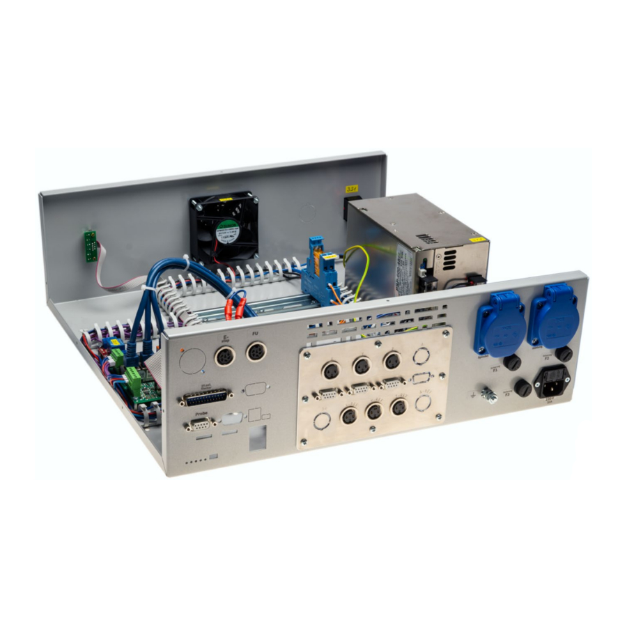
- Page 14 Instructions for control PRO ITG 3 axes Benezan Fig. 20: Jumper for frequency converter connection and emergency stop wiring Fig. 21: Power supply cabling and axis connections Fig. 22: Ribbon cable with D-Sub socket on the rear wall of the housing www.sorotec.de...
- Page 15 Instructions for control PRO ITG 3 axes Benezan Further wiring In any case, test your result with a continuity For this construction phase you will need: tester for contact from one end to the other and 1 Ribbon cable 25pole...
Need help?
Do you have a question about the PRO ITG 3 axes Benezan and is the answer not in the manual?
Questions and answers