
Subscribe to Our Youtube Channel
Related Manuals for THORLABS GVS011


Summary of Contents for THORLABS GVS011
- Page 1 GVS011 and GVS012 GVS111 and GVS112 GVS211 and GVS212 GVS311 and GVS312 GVS411 and GVS412 Large Beam Diameter Scanning Galvo Systems User Guide Original Instructions HA0220T...
-
Page 2: Table Of Contents
Appendix A Specifications ..................24 Appendix B Connecting Legacy Driver Units............27 Appendix C Calculating the Power Dissipation ............32 Appendix D Reasons For Image Distortion ............. 33 Appendix E Regulatory....................35 Appendix F Thorlabs Worldwide Contacts............... 37 Page 0 20381-D02... -
Page 3: Chaper 1 Overview
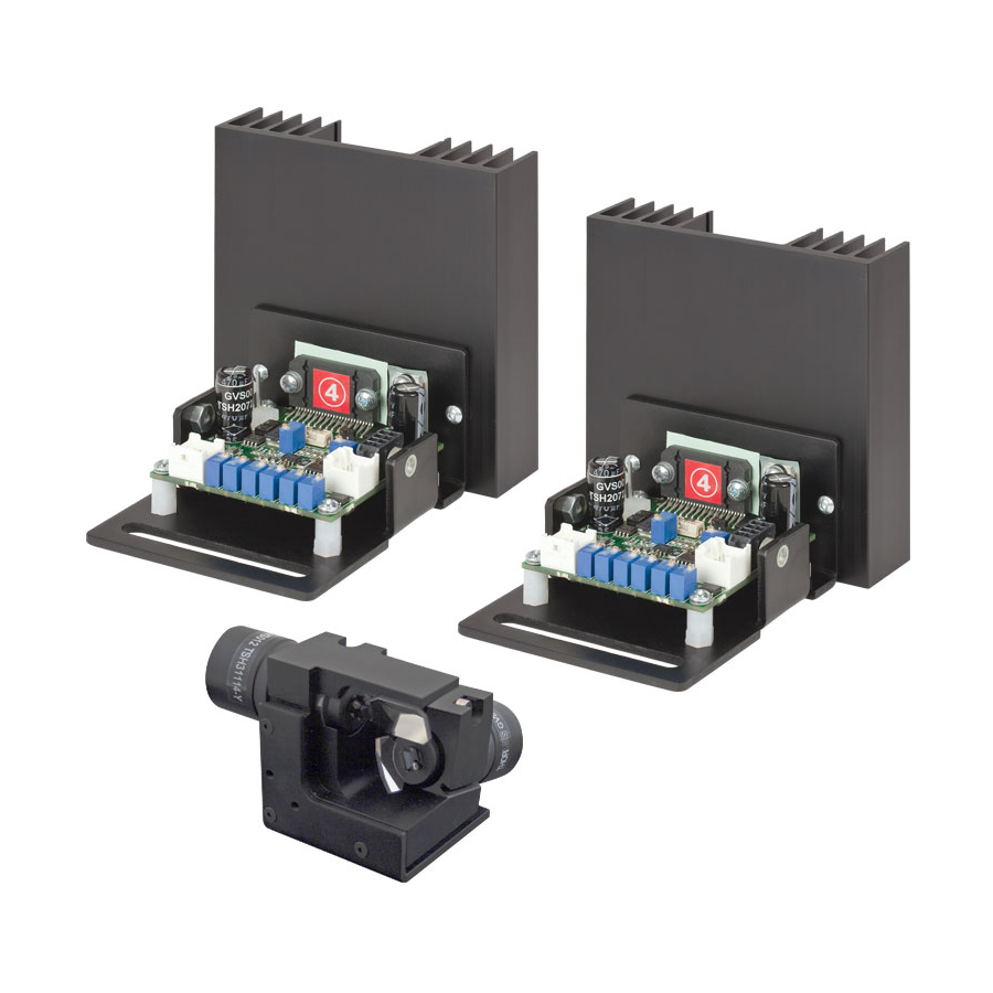
A choice of mirror coating is available as follows: GVS011 and GVS012: Single- and Dual-Axis Systems with Protected Silver Mirrors GVS111 and GVS112: Single- and Dual-Axis Systems with Protected Gold Mirrors GVS211 and GVS212: Single- and Dual-Axis Systems with 400-750 nm Broadband... -
Page 4: System Description
Single- and Dual-Axis Scanning Galvo Systems for Large Beam Diameters 1.2 System Description 1.2.1 Introduction Galvo Scanners are widely used in applications such as laser etching, confocal microscopy, and laser imaging. A galvanometer is a precision motor with a limited travel, usually much less than 360 degrees, whose acceleration is directly proportional to the current applied to the motor coils. - Page 5 Chapter 1 Overview 1.2.3 The Mirror The mirror assembly is attached to the end of the actuator, and deflects the light beam over the angular range of the motor shaft. Scanning galvo applications demand high speed and frequencies of the shaft rotation, and so the inertia of the actuator and mirror assembly can have a profound effect on the performance of the system.
- Page 6 Single- and Dual-Axis Scanning Galvo Systems for Large Beam Diameters 1.2.4 Servo Driver Board The servo circuit interprets the signals from the position detector, then uses positional error, speed and integral of current terms to output control voltages to drive the actuator to the demanded position.
-
Page 7: Chaper 2 Safety
Chapter 2 Safety Chapter 2 Safety 2.1 Safety Information For the continuing safety of the operators of this equipment, and the protection of the equipment itself, the operator should take note of the Warnings, Cautions and Notes throughout this handbook and, where visible, on the product itself. The following safety symbols may be used throughout the handbook and on the equipment itself. - Page 8 Single- and Dual-Axis Scanning Galvo Systems for Large Beam Diameters Caution When connecting the driver boards and motors use only the cables supplied. Do not extend the cables. The driver boards and motors are calibrated with these cables. Using different cables will affect the performance of the system. Caution The driver circuit board is shipped calibrated and ready for use.
-
Page 9: Chaper 3 Installation & Initial Set Up
If the accuracy of the system is in doubt, e.g due to accidental adjustment of trim pots, contact Thorlabs for information on the tuning procedure. During Installation, ensure that the motors are connected to the driver card to which they were tuned. - Page 10 For most applications, the mounting bracket will provide adequate heat sinking, however for more vigorous applications, it may be necessary to fit some heatsinking in addition to the galvo motor mount. Thorlabs supply a heatsink (GHS003) suitable for both single and dual axis applications.
-
Page 11: Electrical Installation
3.2 Electrical Installation 3.2.1 Choosing A Power Supply Thorlabs recommends using the GPS011 linear power supply to power the galvo controller board(s) as this power supply has been specifically designed for this purpose. The GPS011 can power up to two driver cards under any drive conditions and is supplied with all the cables required to connect to the driver cards. - Page 12 Single- and Dual-Axis Scanning Galvo Systems for Large Beam Diameters Caution Both switching and linear power supplies can be used with the Thorlabs galvo systems, however it is important to limit the inrush current when the power supply is turned on, in order to ensure that the power supply reservoir capacitors on the board are not damaged by the large surge currents that can occur on power-up.
- Page 13 Chapter 3 Installation & Initial Set Up 2) Ensure that the correct voltage range and fuse rating for your region is selected. Caution Selecting the incorrect voltage range or fuse will damage the unit. Ensure that both switches are set to the correct position for your region and that the fuse fitted is of the correct rating, as indicated by the screen print on the rear panel.
- Page 14 Up to and including issue 10 Issue 11 onwards Steps (1) to (3) are applicable only if using the Thorlabs GPS011 PSU. 1) Ensure the correct voltage range is selected on the PSU - see vc 2) The circular 3-pin connector on the power output cable and the OUTPUT socket...
- Page 15 Chapter 3 Installation & Initial Set Up orientation. Check for correct orientation of the alignment key ways, then make connections as shown in Fig. 3.6. 3) Screw the outer casing of the plug clockwise until the connector is fully fastened. OUTPUT ±15V DC 3.0A/0.1A, 1.4/6.3 msec OUTPUT...
- Page 16 Single- and Dual-Axis Scanning Galvo Systems for Large Beam Diameters 4) Identify connector J10 on each driver board, and make power connections as shown below. Thorlabs supply a suitable PSU (GPS011) for powering a single or dual axis system (see Section 3.2.1.). A bare cable, crimp connectors (Molex Pt No 2478) and housings for use with general lab PSUs is supplied with each driver board.
- Page 17 Chapter 3 Installation & Initial Set Up 6) Note the serial numbers then connect the galvo motors to their associated driver boards Pin 1 Motor + Coil (power shield floating) Pin 2 Motor -Coil (power shield floating) Pin 3 Not Used Pin 4 Not Used Pin 5 Position Sensor B Current Pin 6 Position Sensor Ground...
- Page 18 Single- and Dual-Axis Scanning Galvo Systems for Large Beam Diameters Pin 1 Command Input +ve Standard O/P Pin 2 Command Input -ve Function 1 2 3 4 Generator Pin 3 DRV OK Pin 4 External Enable Pin 5 -12V Output (low impedence O/P) Differential O/P Pin 6 +12V Output (low impedence O/P) 8 7 6 5...
- Page 19 Chapter 3 Installation & Initial Set Up 3.2.4 Diagnostic Signal Descriptions Scanner Position - This signal is proprotional to the position of the scanner mirror, with a scaling of 0.5 Volts per degree of mechanical movement. Internal Command Signal - The command signal following amplification by the input stage.
-
Page 20: Chaper 4 Operation
Single- and Dual-Axis Scanning Galvo Systems for Large Beam Diameters Chapter 4 Operation 4.1 General Operation 1) Connect the system as described in Section 3.2. 2) Apply power to the driver boards. 3) Input a command signal to each driver board to obtain the desired behaviour. Note After powering the boards, there may be a delay of up to 10 seconds before the motors start to follow the command signal. -
Page 21: Recommended Scanning Angles
Lastly, on dual-axis systems, there is an offset alignment between the X and Y axis mirrors that also limits the scan angle. The table below gives recommended scanning angles for various beam diameters. GVS011, GVS111, GVS211, GVS311 and GVS411 Input Beam Diameter Mechanical Scan Angle... -
Page 22: Chaper 5 Troubleshooting
Single- and Dual-Axis Scanning Galvo Systems for Large Beam Diameters Chapter 5 Troubleshooting 5.1 Common Problems Some of the more common problems encountered when using galvanometers are details below. Motor fails to respond to the command signal This can occur for a number of reasons. The most likely are: 1) power is not correctly applied to the board 2) one of the cables is faulty or not connected properly 3) a fault has been triggered... - Page 23 Chapter 5 Troubleshooting Mirror periodically shoots off to one side and then stops If the mirror suddenly shoot off to one side and then stops it is likely that either the position sensing circuitry is not functioning correctly or the motor cable is incorrectly wired.
- Page 24 Single- and Dual-Axis Scanning Galvo Systems for Large Beam Diameters Overshoot in position signal which grows over time It is possible that the position of the motor may show an overshoot when driven with a large square wave or similar, and that this overshoot will grow with time until a fault is triggered.
-
Page 25: Galvanometer Faults
5.2 Galvanometer Faults The driver electronics monitor numerous signals to ensure the scanners operate safely and the fault protection circuitry will normally prevent any damage. However, the user should be aware that the galvanometer may become permanently damaged if the system becomes unstable (manifested by a screeching noise, self excitation and unpredicable movement of the scanner). -
Page 26: Appendix A Specifications
Front Surface Flatness (@633 nm) Clear Aperture >90% of Dimension Notes a. The input and output beams are offset by 90°. The way our mirrors are tested is continually updated, please consult www.thorlabs.com for more information. Page 24 20381-D02... - Page 27 Appendix A Specifications and Associated Parts Parameter Value Motor & Position Sensor Linearity(50% Full Travel) 99.9% <200 PPM/°C(Max) Scale Drift <20 µRad/°C(Max) Zero Drift Repeatability 15 µRad Resolution With GPS011 Linear PSU 0.00086 ° (15 µRad) With standard switch mode PSU 0.004°...
- Page 28 Single- and Dual-Axis Scanning Galvo Systems for Large Beam Diameters Parameter Value Drive Electronics 25Hz Square wave, Full Travel Bandwidth 35 Hz Sinewave 65Hz Square wave, Bandwidth (50% Full Travel) 130 Hz Sinewave 1kHz Small Angle (±0.2°) Bandwidth 400 µs Small Angle Step Response Power Supply +/-15V to +/-18V dc...
-
Page 29: Appendix B Connecting Legacy Driver Units
Appendix B Connecting Legacy Driver Units Appendix B Connecting Legacy Driver Units Caution This section is applicable only to driver card units, with a PCB earlier than rev 11. For details on connecting later units, please see Section 3.3.3. PCB revisions can be identified as follows: Up to and including issue 10 Issue 11 onwards Page 27... - Page 30 Fig. B.1 Connector Identification 1) Identify connector J10 (see Fig. B.2) on each driver board, and make power connections as shown below. Thorlabs supply a suitable PSU (GPS011) for powering a single or dual axis system (see Section 3.2.1.). A bare cable, crimp connectors (Molex Pt No 2478) and housings for use with general lab PSUs is supplied with each driver board.
- Page 31 Appendix B Connecting Legacy Driver Units Caution During item (2) use only the cables supplied. Do not extend the cables. The driver boards and motors are calibrated with these cables. Using different cables will affect the performance of the system. Longer cables are available as a custom part but the units will require re-calibration if these are not specified at time of order.
- Page 32 Single- and Dual-Axis Scanning Galvo Systems for Large Beam Diameters 4) Using a suitable cable, connect the Diagnostic Terminal J6 to the diagnostic device (e.g. oscilloscope) in your application. Pin identification is given below, signal descriptions are detailed in the next section. Pin 1 Scanner Position Pin 2 Internal Command Signal Pin 3 Positioning Error x 5...
- Page 33 Appendix B Connecting Legacy Driver Units 2.1.2 Setting the Volts/Degree Scaling Factor The servo driver cards have a jumper which is used to set the Volts per Degree scaling factor. The cards are shipped with the scaling set to 0.5 V/°, where the max mechanical scan angle is nominally ±20°...
-
Page 34: Appendix C Calculating The Power Dissipation
Single- and Dual-Axis Scanning Galvo Systems for Large Beam Diameters Appendix C Calculating the Power Dissipation 3.1 Motor Heatsink The power dissipated in the motor can be estimated by measuring the RMS current drawn from the PSU and then using the following equation: x [(I ) / 2] rms+... -
Page 35: Appendix D Reasons For Image Distortion
Appendix D Reasons For Image Distortion Appendix D Reasons For Image Distortion The deflection of a laser beam with a two-mirror system results in three effects: (1) The arrangement of the mirrors leads to a certain distortion of the image field – see Fig. - Page 36 Single- and Dual-Axis Scanning Galvo Systems for Large Beam Diameters As a result, you will find the scanning field turn out to be a "pillow-shaped" image, see Fig. D.2 below. Fig. D.2 Pillow-shaped Field Distortion Caused by the Arrangement of Mirrors Page 34 20381-D02...
-
Page 37: Appendix E Regulatory
Appendix E Regulatory Appendix E Regulatory E.1 Declarations Of Conformity E.1.1 For Customers in Europe See Section E.2. E.1.2 For Customers In The USA This equipment has been tested and found to comply with the limits for a Class A digital device, persuant to part 15 of the FCC rules. - Page 38 Single- and Dual-Axis Scanning Galvo Systems for Large Beam Diameters E.2 CE Certificates Page 36 20381-D02...
-
Page 39: Appendix F Thorlabs Worldwide Contacts
"End of life" units must be returned to Thorlabs or handed to a company specializing in waste recovery. Do not dispose of the unit in a litter bin or at a public waste disposal site. - Page 40 www.thorlabs.com...
Need help?
Do you have a question about the GVS011 and is the answer not in the manual?
Questions and answers