
Subscribe to Our Youtube Channel
Related Manuals for Clarke CDM85

Summary of Contents for Clarke CDM85
- Page 1 OPEN JAW DIGITAL MULTIMETER MODEL NO: CDM85 PART NO: 8133826 USER INSTRUCTIONS ORIGINAL INSTRUCTIONS DL0421 - Rev 2...
-
Page 2: Safety Information
INTRODUCTION Thank you for purchasing this CLARKE CDNM85 Digital Multimeter. Before attempting to use this product, please read these instructions carefully. In doing so you will ensure your safety and you can look forward to your purchase giving you long and satisfactory service. -
Page 3: Electrical Symbols
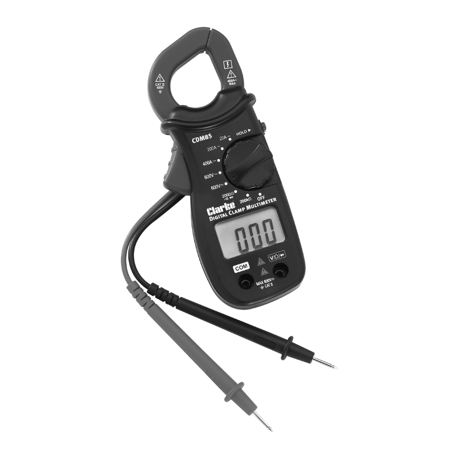
ELECTRICAL SYMBOLS DC (Direct (Alternating Current) Current) Dangerous Important voltage may safety be present information. Refer to the manual Earth Ground Double Insulated Diode Parts & Service: 020 8988 7400 / E-mail: Parts@clarkeinternational.com or Service@clarkeinternational.com... - Page 4 OVERVIEW Description Description Clamp Jaw: Used to “V Q -0+” Jack: Plug0in clamp the conductor jack for the red to be measured. to get (Positive) test lead. more accurate reading, the conductor should be in the centre of the jaws. Trigger: Used to open Rotary Switch: Used to and close the jaws for...
-
Page 5: Specifications
Description Description Display: 3 1/2” LCD, “Hold” Button: After with a max. reading pressing the button, 1999. the present reading is held on the display, meanwhile “HOLD” is displayed on the LCD as an indicator. To exit, press the button again. “COM”... - Page 6 WARNING To avoid possible electric shock or personal injury, follow these guidelines: • Do not use the meter if it is damaged. Before you use the meter, inspect the case. Pay particular attention to the insulation surrounding the connectors. • Inspect the test leads for damaged insulation or exposed metal.
- Page 7 • Remove the test leads from the meter before you open the battery door or measure AC current. • Do not operate the meter with the battery door or portions of the case removed or loosened. • To avoid false readings, which could lead to possible electric shock or personal injury, replace the batteries as soon as the low battery indicator appears.
-
Page 8: Measuring Dc Voltage
• Disconnect circuit power and discharge all high- voltage capacitors before testing resistance,diode and continuity. • Use the proper function and range for your measurements. • Before moving the rotary switch to change functions, disconnect test leads from the circuit under test and remove the clamp jaws from the clamped conductor. -
Page 9: Measuring Ac Current
MEASURING AC CURRENT 1. Set the rotary switch to the desired AC current range position. 2. Press the trigger and clamp the conductor to be measured with the jaws. 3. Make sure that the jaws are perfectly closed. NOTE: a. Each time only one conductor should be clamped. b. -
Page 10: Measuring Diode
MEASURING FOR CONTINUITY 1. Insert the plug of the black test lead to the “COM” jack, the plug of the red test lead to the ‘V Ω ’ jack. 2. Set the rotary switch to the “ “ position. 3. Connect the test leads across the load to be measured. 4. - Page 11 AC VOLTAGE Range Resolution Accuracy Overload Protection 600V ±(1.2%+3) DC 600V AC 600Vrms Input impedance: 9MΩ Frequency Response: 40Hz~400Hz Maximum permited input voltage: 600Vrms DC VOLTAGE Range Resolution Accuracy Overload Protection 600V ±(1.0%+2) DC 600V AC 600Vrms Input impedance: 9MΩ Maximum permited input voltage: 600Vrms RESISTANCE Range...
-
Page 12: Audible Continuity
AC CURRENT Range Resolution Accuracy Overload Protection 10mA ±(3.0%+5) 500A (30 Seconds) 200A 100mA ±(2.5%+5) 500A (30 Seconds) 400A ±(2.5%+5) 500A (30 Seconds) Response: Average, calibrated in rms od a sine wave Frequency range: 50 ~ 60Hz AUDIBLE CONTINUITY Range Resolution Accuracy 1Ω... - Page 13 GENERAL MAINTAINANCE Periodically wipe the case with a damp cloth and mild detergent. Do not use abrasives or solvents. Dirt or moisture in the jacks can affect readings. Clean the jacks as follows: 1. Make sure that no object is clamped in the jaws. 2.
- Page 14 DECLARATION OF CONFORMITY - UKCA Parts & Service: 020 8988 7400 / E-mail: Parts@clarkeinternational.com or Service@clarkeinternational.com...
-
Page 15: Declaration Of Conformity (Ce)
DECLARATION OF CONFORMITY - CE Parts & Service: 020 8988 7400 / E-mail: Parts@clarkeinternational.com or Service@clarkeinternational.com... - Page 16 Parts & Service: 020 8988 7400 / E-mail: Parts@clarkeinternational.com or Service@clarkeinternational.com...
Need help?
Do you have a question about the CDM85 and is the answer not in the manual?
Questions and answers