Landis+Gyr E65C Series User Manual

Landis+Gyr E65C Series User Manual

Communication units provide gsm/gprs communication between e650 or e850 meters and a central system.
Hide thumbs Also See for E65C Series:

Advertisement

Communication
Industrial and Commercial
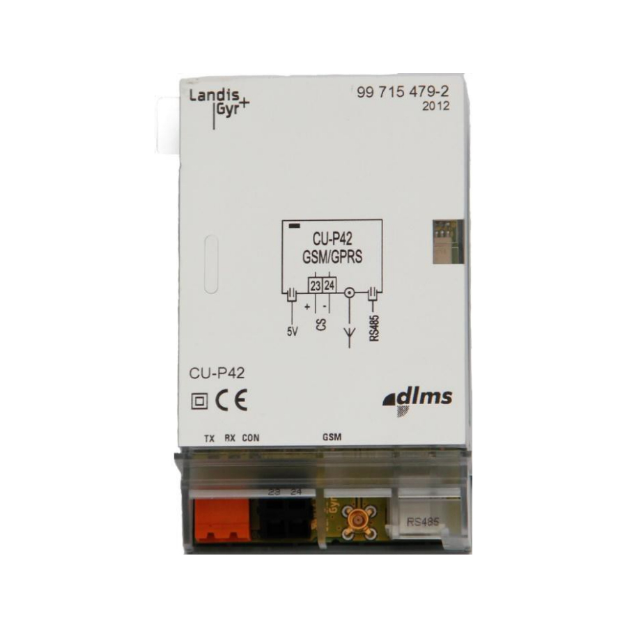
CU-P40, P41, P42
E65C
User Manual
[STATUS]
E65C CU-P40, P41, P42 communication units provide
GSM/GPRS communication between E650 or E850 meters and a central system.
Date: 22.10.2013
File name: D000043188 E65C CU-P4x User Manual en d
© Landis+Gyr
D000043188 en d

Advertisement

Table of Contents
loading
Need help?

Need help?

Do you have a question about the E65C Series and is the answer not in the manual?

Questions and answers

Summary of Contents for Landis+Gyr E65C Series

  • Page 1 CU-P40, P41, P42 E65C User Manual [STATUS] E65C CU-P40, P41, P42 communication units provide GSM/GPRS communication between E650 or E850 meters and a central system. Date: 22.10.2013 File name: D000043188 E65C CU-P4x User Manual en d © Landis+Gyr D000043188 en d...
  • Page 2: Revision History

    Nothing in this document shall be construed as a representation or guarantee in respect of the performance, quality or durability of the specified product. Landis+Gyr accepts no liability whatsoever in respect of the specified product under or in relation to this document.
  • Page 3: Table Of Contents

    LED status description D72 firmware ..................32 Wrong PIN code ........................34 Signal strength indication using LEDs ................... 34 Service ............................35 Troubleshooting ........................35 Repairing the communication unit ..................35 D000043188 en d – E65C – CU-P40, P41, P42 – User Manual © Landis+Gyr...
  • Page 4 4/40 [Status] Table of contents Repairing the 5 V power supply .................... 36 Maintenance ..........................37 Disposal ............................ 38 Index ............................39 D000043188 en d – E65C – CU-P40, P41, P42 – User Manual © Landis+Gyr...
  • Page 5: About This Document

    D000043185 "Technical Data E65C CU-P40, P41, P42"  D000011460 "Functional Description E65C CU A, B, M, G, D, P, E, Q"  D000039353 "User Manual E65C CU-ADP2" D000043188 en d – E65C – CU-P40, P41, P42 – User Manual © Landis+Gyr...
  • Page 6: Device Description

    Landis+Gyr E850 ZxQ high-precision meters Inserted in a CU-adapter CU-ADP2, the communication unit CU-P41 or CU-P42 can also be used with other meters (e.g. Landis+Gyr E650 ZxD300/400xR, ZMD100AR, ZxB or meters from other manufacturers). Connection to the meter is made in this case via an interface in the communication unit (CS, RS232 or RS485).
  • Page 7: Functions

    The serial bi-directional RS485 interface is standardised to ISO-8482. It is basically intended for the connection of several meters (up to 31) using the CU-P42 as the master. D000043188 en d – E65C – CU-P40, P41, P42 – User Manual © Landis+Gyr...
  • Page 8: Safety

    For this purpose, Landis+Gyr provides training on a variety of products and solutions. Please contact your local Landis+Gyr representative if interested. D000043188 en d – E65C – CU-P40, P41, P42 – User Manual...
  • Page 9: Safety Regulations

    Antenna installation must conform to instructions listed in this document. In addition, the safety instructions given in the user manuals for the meter and the CU-adapter CU-ADP2 are also applicable. D000043188 en d – E65C – CU-P40, P41, P42 – User Manual © Landis+Gyr...
  • Page 10: Mechanical Construction

    The communication unit has no seal of its own. It is secured when built-in by a utility seal of the meter or CU-adapter. D000043188 en d – E65C – CU-P40, P41, P42 – User Manual © Landis+Gyr...
  • Page 11: Power Supply, Antenna And Interface Connections

    3.2.1 Connections CU-P40 Fig. 3.3 Connections CU-P40 Input external 5 V power supply (2-pin socket) Antenna connection (MCX socket) Fig. 3.4 Connection diagram communication unit CU-P40 D000043188 en d – E65C – CU-P40, P41, P42 – User Manual © Landis+Gyr...
  • Page 12: Connections Cu-P41

    The RJ12 socket of the RS232 interface has the following pin assignment: Pin No. Terminal Signal Transmitted Data Signal Ground Received Data Fig. 3.6 Connection diagram communication unit CU-P41 D000043188 en d – E65C – CU-P40, P41, P42 – User Manual © Landis+Gyr...
  • Page 13: Connections Cu-P42

    The RJ12 socket of the RS485 interface has the following pin assignment: Pin No. Terminal Signal Signal Ground Data a Data b Data b Data a Signal Ground Fig. 3.8 Connection diagram communication unit CU-P42 D000043188 en d – E65C – CU-P40, P41, P42 – User Manual © Landis+Gyr...
  • Page 14: Faceplate

    The four LEDs TX, RX, CON and GSM designated on the faceplate are fitted on the circuit boards and can be seen through the light guide below the faceplate. Their function is described in section 5 "Operation". D000043188 en d – E65C – CU-P40, P41, P42 – User Manual © Landis+Gyr...
  • Page 15: Installation/De-Installation

    Contact with live parts is dangerous to life. Disconnect the meter from the power supply as described in the meter user manual. D000043188 en d – E65C – CU-P40, P41, P42 – User Manual © Landis+Gyr...
  • Page 16 Preparing the meter for fitting the communication unit Remove the built-in "dummy" communication unit. Insert the communication unit carefully at the place provided in the meter. Ensure correct fitting of the connector. D000043188 en d – E65C – CU-P40, P41, P42 – User Manual © Landis+Gyr...
  • Page 17 Installation/De-installation 17/40 Fig. 4.3 Fitting communication unit in meter Close and seal the front door. D000043188 en d – E65C – CU-P40, P41, P42 – User Manual © Landis+Gyr...
  • Page 18: Fitting In Cu-Adapter Cu-Adp2

    Connect the communication unit to the meter (via RS485, RS232 or CS interface) and the adapter to mains and mount the front cover, see User Manual of the CU-adapter. D000043188 en d – E65C – CU-P40, P41, P42 – User Manual © Landis+Gyr...
  • Page 19: Connecting The Communication Unit

    In addition, areas where there is risk of explosions such as gas stations and oil refineries. D000043188 en d – E65C – CU-P40, P41, P42 – User Manual © Landis+Gyr...
  • Page 20 Humidity, rain and lightning can affect signal strength measurements as well as the frequency band being used. Additional margin beyond the minimum signal level is needed to ensure reliable operation. D000043188 en d – E65C – CU-P40, P41, P42 – User Manual © Landis+Gyr...
  • Page 21: Choosing The Most Suitable Antenna Position In Gsm Mode

    3 m cable is placed inside the building = –89.5 dBm  when antenna with 10 m cable is placed outside the building = –80 D000043188 en d – E65C – CU-P40, P41, P42 – User Manual © Landis+Gyr...
  • Page 22: Choosing The Most Suitable Antenna Position In Gprs Mode

    Level 4 (very good) >–80 dBm In the command tree select the Diagnostic Command "CU GSM Instal- lation Support" to display the current field strength at the antenna. D000043188 en d – E65C – CU-P40, P41, P42 – User Manual © Landis+Gyr...
  • Page 23 Strength Indication" to return to GPRS mode. The LED CON is now lit and the LED GSM flashes twice regularly to indicate that the GPRS mode is active. D000043188 en d – E65C – CU-P40, P41, P42 – User Manual © Landis+Gyr...
  • Page 24 Call the CU via GSM (you can then e.g. change the parameterisation or display the field strength via .MAP110). When the call is ended, the CU activates the GPRS mode. D000043188 en d – E65C – CU-P40, P41, P42 – User Manual © Landis+Gyr...
  • Page 25: Connecting The Cs Interface

    If a connecting wire must be disconnected again for any reason, this is performed in the reverse sequence: Fig. 4.10 Releasing connection from spring-loaded terminal D000043188 en d – E65C – CU-P40, P41, P42 – User Manual © Landis+Gyr...
  • Page 26: Connecting The Rs485 Interface

    Key to table:  Data Terminal Equipment (Computer: PC, Terminal, Laptop)  DCE Data Communication Equipment (PSTN modem, GSM modem)  Communication unit with RS232 interface D000043188 en d – E65C – CU-P40, P41, P42 – User Manual © Landis+Gyr...
  • Page 27 RJ12 cable For connection via a cable with two RJ12 plugs (e.g. from a CU-adapter CU-ADP1 to the meter) the TxD connection must be transposed to RxD. D000043188 en d – E65C – CU-P40, P41, P42 – User Manual © Landis+Gyr...
  • Page 28: Connecting The External 5 V Power Supply For Series 2 Or Older Meters

     The supply voltage phase – neutral is < 100 V, or  The meter has an auxiliary power supply. Landis+Gyr supplies a special terminal cover with integrated 5 V supply and the required connecting cables. Use the following voltage output terminals for connecting the power supply...
  • Page 29: Connecting The External 5 V Power Supply For Series 3 Meters

    > 110 V Phase (8) Neutral (11) F circuit Phase (5) Phase (8) Connect the external 5 V power supply of the CU-P4x as explained in section 4.4.7. D000043188 en d – E65C – CU-P40, P41, P42 – User Manual © Landis+Gyr...
  • Page 30: Final Operations

    D000043188 en d – E65C – CU-P40, P41, P42 – User Manual © Landis+Gyr...
  • Page 31: Commissioning And Functional Check

    Removal/Exchange of communication unit The communication unit is exchanged or removed from the meter in reverse order of the installation (see sections 4.2 and 4.3). D000043188 en d – E65C – CU-P40, P41, P42 – User Manual © Landis+Gyr...
  • Page 32: Operation

    Check the TCP/IP settings of the CU The number of stations includes the serving station and the neighbor cells LED status description D72 firmware D000043188 en d – E65C – CU-P40, P41, P42 – User Manual © Landis+Gyr...
  • Page 33 Check the TCP/IP settings of the CU The number of stations includes the serving station and the neighbor cells D72 firmware display the signal strength D000043188 en d – E65C – CU-P40, P41, P42 – User Manual © Landis+Gyr...
  • Page 34: Wrong Pin Code

    Level 1 (inadequate) <–99 dBm –99 dBm ... –90 dBm Level 2 (sufficient) –89 dBm ... –80 dBm Level 3 (good) Level 4 (very good) >–80 dBm D000043188 en d – E65C – CU-P40, P41, P42 – User Manual © Landis+Gyr...
  • Page 35: Service

    Preferably use the original packing if available. Do not enclose any loose components. Send the communication unit to the responsible service and repair centre. D000043188 en d – E65C – CU-P40, P41, P42 – User Manual © Landis+Gyr...
  • Page 36: Repairing The 5 V Power Supply

    Do not enclose any loose components. Send the terminal cover with built-in 5 V power supply to the responsi- ble service and repair centre. D000043188 en d – E65C – CU-P40, P41, P42 – User Manual © Landis+Gyr...
  • Page 37: Maintenance

    Never use running water for cleaning Communication units must not be cleaned under running water or with compressed air. Water ingress can cause short-circuits or damage com- ponents. D000043188 en d – E65C – CU-P40, P41, P42 – User Manual © Landis+Gyr...
  • Page 38: Disposal

    On request, Landis+Gyr will provide more information about the environmental impact of the product. Disposal and environmental protection regulations ...
  • Page 39: Index

    ........... 15 TCP/IP ............7 Fitting in Troubleshooting ..........35 CU-adapter ..........18 Type designation ..........6 Functional check .......... 31 Versions ............6 D000043188 en d – E65C – CU-P40, P41, P42 – User Manual © Landis+Gyr...
  • Page 40 Contact: Landis+Gyr AG Theilerstrasse 1 CH-6301 Zug Switzerland Phone: +41 41 935 6000 www.landisgyr.com...

This manual is also suitable for:

Cu-p40Cu-p41Cu-p42

Table of Contents

Save PDF