Sign In
Upload
Download
Table of Contents
Contents
Add to my manuals
Delete from my manuals
Share
URL of this page:
HTML Link:
Bookmark this page
Add
Manual will be automatically added to "My Manuals"
Print this page
×
Bookmark added
×
Added to my manuals
Manuals
Brands
Landis+Gyr Manuals
Conference System
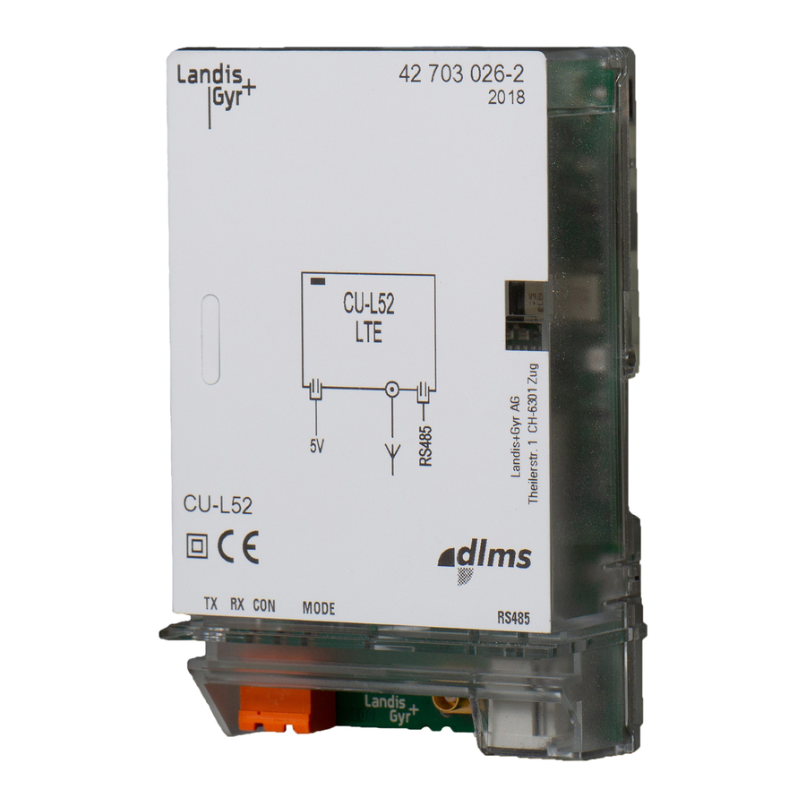
CU-B1
User manual
Landis+Gyr CU-B1 User Manual
Communication unit
Hide thumbs
1
2
Table Of Contents
3
4
5
6
7
8
9
10
11
12
13
14
15
16
17
18
19
20
21
22
23
24
25
26
27
28
29
30
page
of
30
Go
/
30
Contents
Table of Contents
Bookmarks
Table of Contents
Revision History
Table of Contents
About this Document
1 Device Description
Review
General View
Purpose of Use
Type Designation
Technical Data
Inputs and Outputs
External Influences
Weight and Dimensions
Connections
Connection Diagram
2 Safety
Safety Information
Responsibilities
Safety Regulations
3 Mechanical Construction
4 Function
Pulse Inputs (S0 Interfaces)
RS485 Interface
RS232 Interface
Receive and Transmit Times
Function of Leds
Application of Interfaces
5 Installation and Commissioning
Introduction
Material and Tools Required
Fitting the Communication Unit CU-Bx
Connecting the Communication Unit CU-Bx
Connecting the Signal Inputs
Connecting the Communication Interfaces
Pin Allocation RS232
Connecting the RS485 Interface
Commissioning and Functional Check
6 Measures in Event of Faults
Removing the Communication Unit CU-Bx
Repairing the Communication Unit CU-Bx
7 Decommissioning and Disposal
8 Index
Advertisement
Quick Links
1
Review
2
General View
3
Technical Data
4
Inputs and Outputs
5
Connections
6
Rs485 Interface
7
Connecting the Rs485 Interface
Download this manual
Communication
Industrial and Commercial
CU-B1, B2, B4
E65C
User Manual
Date: 18.04.2016
File name: D000011142 E65C CU-Bx User Manual en k.docx
© Landis+Gyr
D000011142 en k
Table of
Contents
Previous
Page
Next
Page
1
2
3
4
5
Advertisement
Table of Contents
Need help?
Do you have a question about the CU-B1 and is the answer not in the manual?
Ask a question
Questions and answers
Related Manuals for Landis+Gyr CU-B1
Conference System Landis+Gyr CU-B2 User Manual
Communication unit (30 pages)
Conference System Landis+Gyr CU-B4 User Manual
Communication unit (30 pages)
Conference System Landis+Gyr E65C Series User Manual
Communication units provide gsm/gprs communication between e650 or e850 meters and a central system. (40 pages)
Conference System Landis+Gyr CU-P42 User Manual
Communication units provide gsm/gprs communication between e650 or e850 meters and a central system. (40 pages)
This manual is also suitable for:
Cu-b2
Cu-b4
E65c
Table of Contents
Print
Rename the bookmark
Delete bookmark?
Delete from my manuals?
Login
Sign In
OR
Sign in with Facebook
Sign in with Google
Upload manual
Upload from disk
Upload from URL


Need help?
Do you have a question about the CU-B1 and is the answer not in the manual?
Questions and answers