Table of Contents
Advertisement
Available languages
Available languages
Quick Links
IMPORTANT!
Read all instructions before installing and using. Installer: This manual must be
delivered to the end user.
Do not install and/or operate this safety product unless you have read and understand the safety
information contained in this manual.
1. Proper installation combined with operator training in the use, care, and maintenance of emergency safety devices are essential to ensure the safety of you and those you are
seeking to protect.
2. Exercise caution when working with live electrical connections.
3. This product must be properly grounded. Inadequate grounding and/or shorting of electrical connections can cause high current arcing,which can cause personal injury and/or
severe vehicle damage, including fire.
4. Proper placement and installation are vital to the performance of this safety device. Install this product so that output performance of the system is maximized and the controls
are placed within convenient reach of the operator so that s/he can operate the system without losing eye contact with the roadway.
5. Do not install this product or route any wires in the deployment area of an air bag. Equipment mounted or located in an air bag deployment area may reduce the effectiveness
of the air bag or become a projectile that could cause serious personal injury or death. Refer to the vehicle owner's manual for the air bag deployment area. It is the responsi-
bility of the user/operator to determine a suitable mounting location ensuring the safety of all passengers inside the vehicle particularly avoiding areas of potential head impact.
6. It is the responsibility of the vehicle operator to ensure during use that all features of this product work correctly. In use, the vehicle operator should ensure the projection of
the safety signal is not blocked by vehicle components (i.e., open trunks or compartment doors), people, vehicles or other obstructions.
7. The use of this or any other safety device does not ensure all drivers can or will observe or react to a warning signal. Never take the right-of way for granted. It is your respon-
sibility to be sure you can proceed safely before entering an intersection, driving against traffic
8. This equipment is intended for use by authorized personnel only. The user is responsible for understanding and obeying all laws regarding warning signal devices. Therefore,
the user should check all applicable city, state, and federal laws and regulations. The manufacturer assumes no liability for any loss resulting from the use of this safety
device.
Note:
Black die cast aluminum housing gets very hot to the touch after operating constantly for several hours.
Specifications:
Size:
EW3007-F
EW2604
Weight:
EW3007-F
EW2604
Voltage:
Temperature Range:
Prior to installation:
Carefully remove the unit from its packaging. If damage is found, contact the transit company or ECCO. Do not use broken or damaged
parts. Prior to mounting, consideration should be given to cable location.
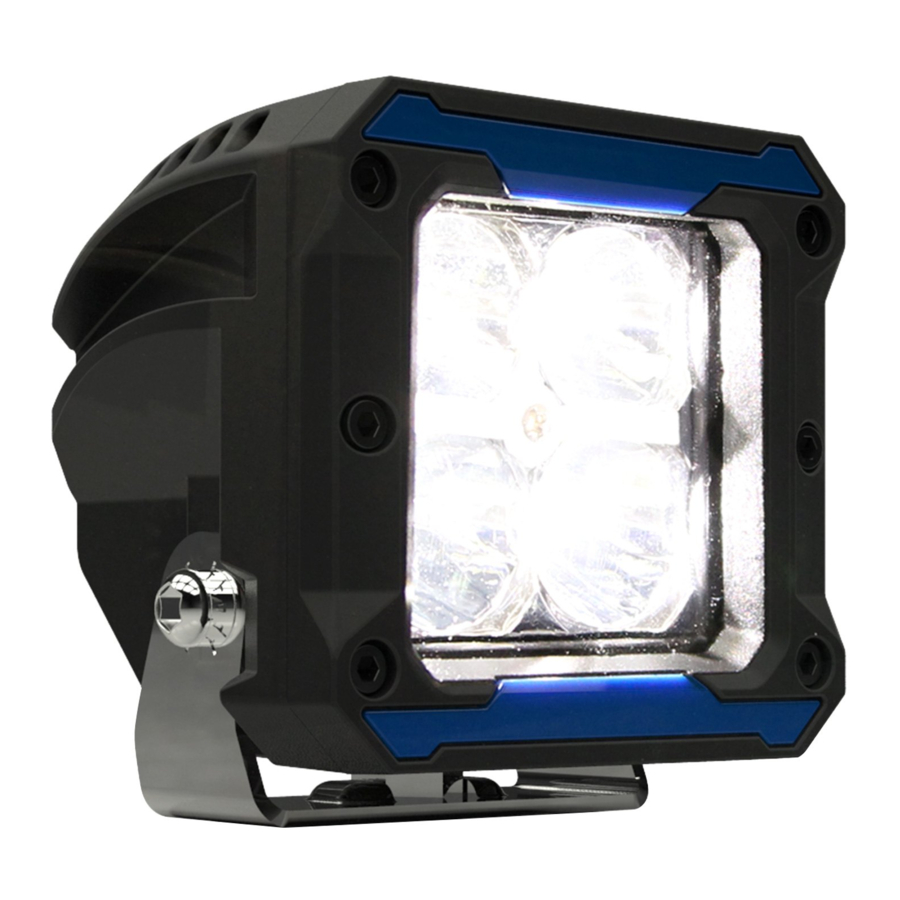
EW3007-F Mounting:
1. Drill a hole in the mounting surface matching the hole in the bracket.
2. Insert the hex head bolt through the center of the mounting bracket and
loosely assemble the bracket onto the light as shown.
3. Secure the light in place with the supplied hardware. Adjust the light
beam angle as needed before tightening the screw on each side with
the included hex key.
Installation and Operation Instructions
EW3007-F AND EW2604 WORKLIGHTS
3.3"W X 3.3"H X 3.0"D
7.0"W X 4.3"H X 2.8"D
1.3 lbs.
2.8 lbs.
12-24 VDC
-40° to 150°F
-40° to 65°C
,
responding at a high rate of speed, or walking on or around traffic lanes.
Peak Current Draw at 12.8 VDC:
EW3007-F
EW2604
Max Power Draw at 12.8 VDC:
EW3007-F
EW2604
1.0A
2.1A
13.1W
26.9W
Mounting Surface
FIGURE 1
Page 1 of 3
Advertisement
Table of Contents

Subscribe to Our Youtube Channel
Related Manuals for Ecco EW3007-F


Summary of Contents for Ecco EW3007-F
- Page 1 -40° to 65°C Prior to installation: Carefully remove the unit from its packaging. If damage is found, contact the transit company or ECCO. Do not use broken or damaged parts. Prior to mounting, consideration should be given to cable location.
-
Page 2: In-Line Switch
EW2604 Mounting: 1. Disassemble the mounting bracket from the light. Drill two holes in the mounting surface matching the holes in the bracket. 2. Insert the hex head bolts through the mounting bracket and loosely assemble the bracket onto the light as shown. 3. - Page 3 Electronics Controls Company “ECCO” (Manufacturer) ECCO warrants that on the date of purchase, this product will conform to ECCO’s specifications for this product (which are available from ECCO upon request). This Limited Warranty extends for sixty (60) months from the date of purchase.
-
Page 4: Specifications
Antes de la instalación: Retire con cuidado la unidad de su embalaje. Si encuentra daños, póngase en contacto con la empresa de transporte o con ECCO. No utilice piezas rotas o dañadas. Antes del montaje, debe tenerse en cuenta la ubicación del cable. - Page 5 Montaje de EW3007-F: 1. Desmonte el soporte de montaje de la luz. Perfore dos orificios en la superficie de montaje que coincidan con los orificios del soporte. 2. Inserte los pernos Allen a través del soporte de montaje y monte sin apretar el soporte en la luz, tal y como se indica.
- Page 6 833 West Diamond St Boise, Idaho 83705 Servicio al cliente EE.UU. 800.635.5900 Reino Unido +44 (0)113 237 5340 AUS +61 (0)3 63322444 www.eccoesg.com An ECCO SAFETY GROUP™ Brand www.eccosafetygroup.com ©2019 ECCO 920-0749-00 Rev. B Página 3 de 3...
-
Page 7: Instructions D'installation Et D'utilisation
-40° a 65°C Avant l’installation: Retirer délicatement l’appareil de son emballage. En cas de dommage, contacter la société de transport ou ECCO. Ne pas utiliser de pièces brisées ou endommagées. Avant le montage, il convient de tenir compte de l’emplacement du câble. - Page 8 EW3007-F Montage: 1. Démonter le support de montage du feu. Percer deux trous dans la surface de montage correspondant aux trous dans le support. 2. Insérer les boulons à tête hexagonale à travers le support de montage et monter le support sans le serrer sur le feu, comme il- lustré.
- Page 9 à l’autre. Certaines juridictions ne permettent pas l’exclusion ou la limitation des dommages indirects ou consécutifs. 833 West Diamond St Boise, Idaho 83705 Le Service Client États-Unis 800.635.5900 Royaume-Uni +44 (0)113 237 5340 AUS +61 (0)3 63322444 www.eccoesg.com An ECCO SAFETY GROUP™ Brand www.eccosafetygroup.com ©2019 ECCO 920-0749-00 Rev. B Page 3 sur 3...
Need help?
Do you have a question about the EW3007-F and is the answer not in the manual?
Questions and answers