Table of Contents
Advertisement
Available languages
Available languages
Quick Links
Advertisement
Chapters
Table of Contents

Related Manuals for VOLTCRAFT MS 18-2


Summary of Contents for VOLTCRAFT MS 18-2
- Page 1 Bedienungsanleitung Multitester MS-18/2 Best.-Nr. 120747 Seite 2 - 10 Operating Instructions Multitester MS-18/2 Item No. 120747 Page 11 - 18 Notice d’emploi Multitesteur MS-18/2 N° de commande 120747 Page 19 - 27...
-
Page 2: Table Of Contents
Inhaltsverzeichnis Seite Einführung ................................3 Symbol-Erklärung ..............................3 Bestimmungsgemäße Verwendung ........................4 Produktbeschreibung ............................4 Lieferumfang ................................5 Sicherheitshinweise .............................5 Einzelteilbezeichnung ............................6 Bedienung ................................6 a) Einlegen der Batterien/Batteriewechsel ......................6 b) Selbsttest ...............................7 c) Wechselspannungs-Detektion ........................7 d) Gleichspannungstest (1,2 bis 35 VDC) ......................8 e) Durchgangsprüfung 0 – 5 MOhm (direkter Kontakt) ..................8 f) Mikrowellenleck-Test ( >... -
Page 3: Einführung
1. Einführung Sehr geehrter Kunde, wir bedanken uns für den Kauf des Multitesters. Mit diesem Gerät haben Sie ein Produkt erworben, welches nach dem heutigen Stand der Technik gebaut wurde. Die- ses Produkt erfüllt die Anforderungen der geltenden europäischen und nationalen Richtlinien. Die Konformität wurde nachgewiesen, die entsprechenden Erklärungen und Unterlagen sind beim Hersteller hinterlegt. -
Page 4: Bestimmungsgemäße Verwendung
LED-Anzeige noch 0,5 bis 2 Sekunden verzögert um eine exaktes und eindeutiges Messergebnis zu erreichen. Mit dem MS 18-2 können Sie an spannungsführenden Leitungen und Teilen überprüfen, ob Wechselspannung an- liegt. Die kann sowohl im direkten Kontakt oder auch berührungslos (indirekt) erfolgen. Die Indirekte Messung ist vor allem bei isolieren Leitungen und Teilen sehr hilfreich. Weiterhin kann die Polarität von Gleichspannungsquellen ermittelt werden. -
Page 5: Lieferumfang
5. Lieferumfang • Multitester MS 18-2 • zwei Knopfzellen • Bedienungsanleitung Aktuelle Bedienungsanleitungen Laden Sie aktuelle Bedienungsanleitungen über den Link www.conrad.com/downloads herunter oder scannen Sie den abgebildeten QR-Code. Befolgen Sie die Anweisungen auf der Webseite. 6. Sicherheitshinweise Bei Schäden, die durch Nichtbeachten dieser Bedienungsanleitung verursacht werden, erlischt der Garantieanspruch! Für Folgeschäden übernehmen wir keine Haftung! -
Page 6: Einzelteilbezeichnung
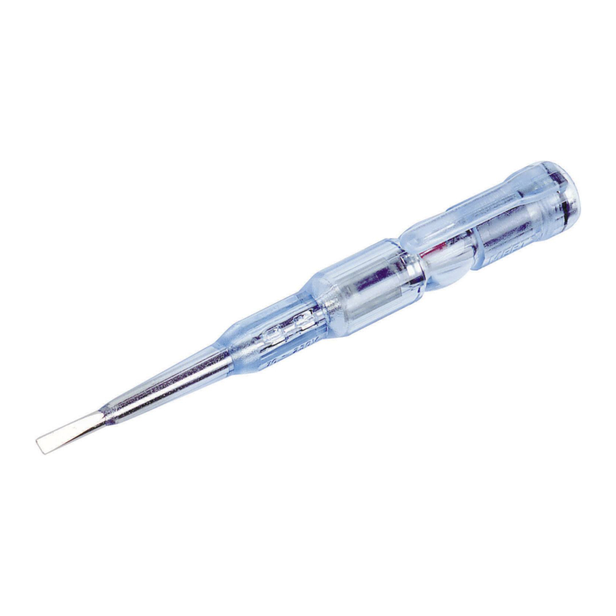
7. Einzelteilbezeichnung 1 Messspitze 2 Anzeige LED 3 Batteriefachdeckel 8. Bedienung a) Einlegen der Batterien/Batteriewechsel Der Multitester benötigt zum Betrieb zwei Knopfzellen des Typs 392A, AG3, LR41, 192 (oder baugleich). Um einen elektrischen Schlag zu vermeiden, darf der Multitester nicht in geöffneten Zustand betrieben werden. -
Page 7: B) Selbsttest
b) Selbsttest Um Fehlindikationen zu vermeiden, muss vor jedem Gebrauch und nach jedem Batteriewechsel die Funktionsfähig- keit des Multitesters durch einen Selbsttest überprüft werden. Überprüfen Sie vor jedem Gebrauch das Gerät auf Beschädigung(en) wie z.B. Gehäusebruch usw. Berühren Sie die Spitze (1) des Testers mit einer Hand und gleichzeitig mit der ande- ren Hand den Batteriefachdeckel (3) Wenn die rote LED (2) zu blinken beginnt, ist der Multitester in Ordnung und darf benutz werden. -
Page 8: D) Gleichspannungstest (1,2 Bis 35 Vdc)
d) Gleichspannungstest (1,2 bis 35 VDC) Mit dieser Funktion identifiziert der MS18-2 die Polarität von Gleichspannungsquellen wie Batterien, Akkus, usw. Berühren Sie mit einem Finger einen Pol der zu Überprüfenden Batterie. Berühren Sie mit der Messspitze (1) den anderen Pol der Batterie (Batteriefachdeckel berühren). Beginnt die LED (2) zu leuchtet oder blinken, ist der Pol welcher mit der Messspitze verbunden ist der Plus-Pol, bleibt die LED dunkel berühren Sie den Minus Pol. -
Page 9: F) Mikrowellenleck-Test ( > 5 Mw/Cm )
f) Mikrowellenleck-Test ( > 5 mW/cm Achtung! Mikrowellenstrahlung ist gefährlich! Dieser Tester ist nicht mit einem Hightech-Gerät vergleichbar. Solche Messgeräte kosten ein Vielfaches mehr. Betrachten Sie daher diesen Test nur als Anhaltspunkt für evtl. vorhandene Mikrowellenstrahlung. • Schalten Sie Ihre Mikrowelle ein. • Berühren Sie mit einer Hand den Batteriefachdeckel (3) und führen Sie die Testspitze des Multitesters langsam an der Tür der Mikrowelle entlang. Ist die Türdichtung der Mikrowelle undicht, beginnt die LED zu blinken. In diesem Fall darf die Mikrowelle nicht mehr betrieben werden. -
Page 10: Technische Daten
11. Technische Daten Spannungsversorgung ........3 V (2 x 1,5 V Knopfzelle) Batterietyp ............392A, AG3, LR41, 192 (oder baugleich) Schutzklasse ............2 (Schutzisoliert) Überspannungskategorie .........CAT II Spannungsmessbereich ........direkt 70 V bis 250 VAC Wechselspannung ..........indirekt 70 V bis 500 VAC Polaritätsprüfung ..........1,2 V bis 35 V DC (Gleichspannung) Frequenzbereich ..........50 bis 500 Hz Durchgangsprüfung ..........0 bis 50 MΩ... - Page 11 Table of contents Page 1. Introduction ................................12 Explanation of symbols ............................12 3. Intended use ..............................12 Product description ............................13 Delivery content ..............................13 Safety instructions .............................14 Description of individual components ........................14 Operation ................................15 a) Inserting the battery / Changing of battery ....................15 b) Self-test ...............................15 c) Alternating voltage detection ........................16 d) Direct voltage test (1.2 to 35 VDC) ......................16 e) Continuity check 0 –...
-
Page 12: Introduction
1. Introduction Dear customer, Thank you for your purchasing the multitester. With this product you have bought a state of the art product. This product satisfies the standards of the established European and national guidelines. CE-conformity has been proven, the relevant documents are in the manufacturer’s possession. We kindly request the user to respect this operating manual to preserve this condition and to ensure safe operation. -
Page 13: Product Description
70 percent. MS18-2 furthermore has a temporary memory function which delays the LED display a further 0.5 to 2 seconds in order to achieve precise and definite measuring results. With the MS 18-2 you can check voltage-carrying electric lines and part, whether alternating voltage is applied. This can be carried out either with direct contact or contactless (indirect). The indirect measuring can be especially helpful with insulated lines and parts. -
Page 14: Safety Instructions
6. Safety instructions In the case of any damages which are caused due to failure to observe these operating instructions, the guarantee will expire. We do not assume liability for resulting damages. An exclamation mark inside a triangle points to important notes in the operating manual. Please read through the entire manual before putting the device into operation. -
Page 15: Operation
8. Operation a) Inserting the battery / Changing of battery To operate the multitester two round cell batteries type 392A, AG3, LR41, 192 (or identically constructed) are needed. To avoid an electric shock the multitester must not be operated when open. After each battery change a self-test needs to be carried out. -
Page 16: C) Alternating Voltage Detection
c) Alternating voltage detection Direct contact (70 to 250 V alternating voltage) Touch the electric conductor (phase) with the measuring tip (1). If the LED (2) lights up, there is voltage. During this test the battery compartment lid must not be touched with the finger. Indirect contact (70 to 500 V alternating voltage) During this test the tip of the tester must not touch the tested line (device) directly. Please note that the LED (2) only goes out after approx. 0.5 to 2 seconds after removing the device from the voltage because of the temporary memory function. -
Page 17: E) Continuity Check 0 - 5 Mohm (Direct Contact)
e) Continuity check 0 – 5 MOhm (direct contact) Touch the battery compartment lid (3) with one hand and with the other hand the contact of the component to be tested (e.g., light bulb). Guide the tip of the multit- ester to another contact. If the LED (2) starts to light up or blink, continuity is given and the light bulb is in working order. -
Page 18: Disposal
10. Disposal a) General The product must not be disposed in the household waste. Dispose of the product at the end of its serviceable life in accordance with the current statutory require- ments; e.g., return it to any suitable collection point. Remove any normal or rechargeable batteries inserted and dispose of them separately from the product. - Page 19 Sommaire Page 1. Introduction ................................20 Explication des symboles ..........................20 Utilisation conforme ............................21 Description du produit ............................21 Contenu de l’emballage .............................22 Modes d‘emploi actuels .............................22 Consignes de sécurité ............................22 Description des éléments ..........................23 Mode d’emploi ..............................23 a) Installation des piles /Changement des piles ....................23 b) Autocontrôle ..............................24 c) Détection d’une tension alternative ......................24 d) Test sur tension continue (1,2 à...
-
Page 20: Introduction
1. Introduction Cher client, nous vous remercions de l’achat du Multitesteur MS-18/2. Avec ce produit, vous avez fait l’acquisition d’un produit construit d’après les derniers progrès de la technique. Ce produit est conforme aux exigences des directives européennes et nationales en vigueur. La conformité a été vérifiée et les notices correspondantes ont été déposées chez le fabricant. Afin de maintenir l’appareil en bon état et d’en assurer l’exploitation sans risques, l’utilisateur doit absolument tenir compte de ce mode d’emploi! Pour toute question technique, veuillez vous adresser à:... -
Page 21: Utilisation Conforme
4. Description du produit Le Multitesteur MS 18-2 est le perfectionnement technique du Multitesteur MS 18 bien connu. En supplément des fonctions dont était pourvu le MS-18, le MS 18-2 est équipé d’un système électronique de mesurage permettant une économie de consommation de courant de jusqu’à environ 70%. Afin d’obtenir un résultat de mesure exact et clair, le MS 18-2 est de plus équipé d’une mémoire temporaire qui retarde l’affichage du voyant LED de 0,5 à 2 secondes. -
Page 22: Contenu De L'emballage
5. Contenu de l’emballage • Multitesteur MS 18-2 • 2 piles boutons • Mode d’emploi Modes d‘emploi actuels Téléchargez les modes d‘emplois actuels sur le lien www.conrad.com/downloads ou bien scannez le code QR représenté. Suivez les indications du site internet. -
Page 23: Description Des Éléments
7. Description des éléments 1 Pointe de mesure 2 Voyant LED 3 Couvercle du compartiment à piles 8. Mode d’emploi a) Installation des piles /Changement des piles Le Multitesteur a besoin pour fonctionner de 2 piles boutons de type 392A, AG3, LR41, 192 (ou de type similaire). Afin d’éviter une électrocution, n’utilisez jamais le Multitesteur ouvert. Après chaque changement de piles, un autocontrôle doit être effectué. -
Page 24: B) Autocontrôle
Ce test ne peut pas être effectué sur des câbles blindés. Pour un contrôle rapide de prises de courant, de convertisseurs ou de câbles revêtus de C.P.V., tenez le MS 18-2 par la pointe de mesure (1) et faites passer le manche à proximité de l’appareil à tester. -
Page 25: D) Test Sur Tension Continue (1,2 À 35 Vcc)
Test sur tension continue (1,2 à 35 VCC) Avec cette fonction, le MS 18-2 détermine la polarité de sources de tension continue, tels piles, accus etc. Touchez avec un doigt un pôle de la pile à tester et touchez avec la pointe de mesure (1) l’autre pôle de la pile. -
Page 26: F) Détection De Fuites De Micro-Ondes ( > 5 Mw/Cm )
f) Détection de fuites de micro-ondes ( > 5 mW/cm Attention ! Le rayonnement de micro-ondes est dangereux ! Ce testeur ne peut pas être comparé à un appareil de haute-technologie. De tels instruments de mesure coûtent beaucoup plus cher. Ce test ne peut donc être considéré... -
Page 27: Caractéristiques Techniques
11. Caractéristiques techniques Alimentation en courant ........3 V (2 x 1,5 V piles bouton) Type de pile ............392A, AG3, LR41, 192 (ou de type similaire) Classe de protection .........2 (à double isolation) Catégorie de surtension ........CAT II Plage de mesure de tension ......directe 70 V à 250 VCA Tension alternative ..........indirecte 70 V à... - Page 28 Dies ist eine Publikation der Conrad Electronic SE, Klaus-Conrad-Str. 1, D-92240 Hirschau (www.conrad.com). Alle Rechte einschließlich Übersetzung vorbehalten. Reproduktionen jeder Art, z. B. Fotokopie, Mikroverfilmung, oder die Erfassung in elektronischen Datenverarbeitungsanlagen, bedürfen der schriftlichen Genehmigung des Herausgebers. Nachdruck, auch auszugsweise, verboten. Die Publikation entspricht dem technischen Stand bei Drucklegung. Copyright 2019 by Conrad Electronic SE.
Need help?
Do you have a question about the MS 18-2 and is the answer not in the manual?
Questions and answers