Table of Contents
Advertisement
Quick Links
Advertisement
Table of Contents

Related Manuals for Trolex Sentro 8


Summary of Contents for Trolex Sentro 8
-
Page 3: Table Of Contents
4.2.2 Sensor Inputs Overview Application 4.2.3 Relay Outputs Overview Product Options 4.2.4 Audio/Visual Alarms Dimensions Overview 1.4.1 TX9165 Sentro 8 Sensorstation Main Setup Menu - Four Gas Ports 4.3.1 Security 1.4.2 TX9165 Sentro 8 Sensorstation 4.3.2 Display - Eight Gas Ports 4.3.3 Time and Date... - Page 4 Message 8.7 .1 Power-up Replacing a Sentro Sensing 8.7 .2 Power Down Module Maintenance Low Supply Voltage 8.8.1 Sentro 8 and Battery Latched Relay Message and Back-up - Check Relay Reset 8.8.2 Battery Back-up Discharge Maintenance - Test 7 .1 Sentro eModules and 8.8.3 Battery Back-up Cells...
-
Page 5: Product Overview
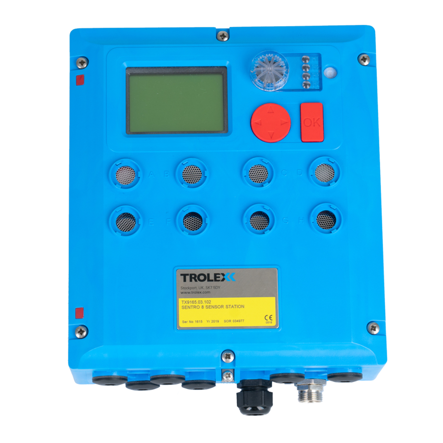
TX9165 User Manual Product Overview TX9165 Sentro 8 Sensorstation TX9165 Sentro 8 Sensorstation (eight gas ports) (four gas ports) Operating Features • Integrated eight channel sensing and control unit for environmental and machine condition monitoring including eModule • Toxic gases •... -
Page 6: Application
12 V dc from an approved Supply voltage: source Exi approved,12 V dc supply Remote sensors: Suitable for, and clearance Output relay contacts: compatible for, switching other intrinsically safe circuits Type of protection: Intrinsically safe, EX ia Category: 94/9/EC ATEX: TX9165-UM-EN-07 www.trolex.com... -
Page 7: Product Options
TX9165 User Manual Product Options TX9165 Sentro 8 Sensorstation Mining Ex General Purpose 12 V dc TX9165.01 24 V dc TX9165.03.102 85 to 265 V ac (universal) TX9165.03.114 www.trolex.com TX9165-UM-EN-07... -
Page 8: Dimensions
Dimensions 1.4.1 TX9165 Sentro 8 Sensorstation - Four Gas Ports TX9165-UM-EN-07 www.trolex.com... -
Page 9: Tx9165 Sentro 8 Sensorstation
TX9165 User Manual 1.4.2 TX9165 Sentro 8 Sensorstation - Eight Gas Ports www.trolex.com TX9165-UM-EN-07... -
Page 10: Technical Information
Confidence Alert flash and audible tone at 15 second intervals • High-brightness, area warning, flashing alarm and audible alarm • Function configurable Audible alarm: • High intensity audible sounder 95 dB at 300 mm • Function configurable • Mute function Gas infusion: • Natural diffusion TX9165-UM-EN-07 www.trolex.com... - Page 11 4000 readings per sensor with time, date and alarm event report Datacomms: • RS485 datacomms output supporting up to 32 Sentro 8 Sensorstations on a single Modbus network in multidrop mode to a standard PC • System reporting www.trolex.com TX9165-UM-EN-07...
-
Page 12: Electrical Details
Four independent alarms relays each programmable to any Output relays alarm setpoint on any monitoring channel for preferred alarm priority grouping Relay contacts One changeover contact on each relay Suitable for, and clearance Contact rating compatible for, intrinsically 2 Amps 230 V ac safe circuits TX9165-UM-EN-07 www.trolex.com... -
Page 13: Sentro Sensing Modules
• Each eModule and rModule stores all the necessary data about its type, identification, sensing range and specific calibration. This data is automatically recognised by Sentro 8 Sensorstation when the eModule or rModule is plugged into the module bay •... -
Page 14: Sentro Emodules
1.7.1 Sentro eModules For the full range of Sentro eModules refer to the Sentro 8 Product Data Sheet TX9165-DS-EN or contact the Trolex Sales Team: sales@trolex.com 1.7.1.1 Flammable Gases • Poison Resistant Catalytic Sensor The sensor will respond to most flammable gases and vapours to varying degrees;... - Page 15 5 ppm alarm 30 ppm 100 ppm 200 ppm 10 ppm 10 ppm HIGH alarm 200 ppm 200 ppm 200 ppm 10 ppm 5 ppm STEL & TWA 30 ppm 30 ppm 30 ppm 5 ppm 2 ppm www.trolex.com TX9165-UM-EN-07...
- Page 16 -10 to +40°C temperature GENERAL 5 ppm 2.5 ppm 19% (under) 5 ppm 250 ppm alarm 10 ppm 5 ppm 23% (over) 20 ppm 500 ppm HIGH alarm 5 ppm 10 ppm STEL & TWA 3 ppm 3 ppm TX9165-UM-EN-07 www.trolex.com...
- Page 17 Periodic calibration of the gas sensor should be carried out whilst it is in service. For oxygen and carbon monoxide gas sensors Trolex recommends that this is carried out every 3 weeks. For other gas sensors Trolex recommends that this is carried out in accordance with best practice for the industry where the gas sensor is being used, and should take into consideration local operating conditions.
- Page 18 The sensor should be powered-up and the nitrogen applied for at least 5 minutes to ensure that the sensor has stabilised. TX9165-UM-EN-07 www.trolex.com...
-
Page 19: Sensing
All eight positions (A to H) in the Sentro 8 Sensorstation can be fitted with rModules in positions where no eModules are being used. Industrial standard analogue sensor 4 to 20 mA TX9160.301... -
Page 20: Certification
Special Conditions for Safe Use of Sentro eModules and rModules The minimum ingress protection stated in the Ex-certificates for the Sentro eModules and rModules are satisfied when mounted in the Sentro 8 Sensorstation, as are the conditions for impact protection and external fuse protection in the case of the infrared eModule. - Page 21 Points to note relating to Sentro eModules and rModules The minimum ingress protection stated in the Ex-certificates for the Sentro eModules and rModules are satisfied when mounted in the Sentro 8 Sensorstation, as are the conditions for impact protection and external fuse protection in the case of the infrared eModule.
- Page 22 The Ui presented by an externally powered sensor to any rModule, terminals 2m or 3m, shall not exceed the 14.4 V. Russia Certification (Customs Union) TX9165.01.i Sentro 8 Sensorstation (Group 1) Ex Certificate Number: RU C-GB.ГБ05.B.00616 Ex Certificate Code: PO Ex ia I Ma X General Conditions for Safe Use –...
- Page 23 TX9165 User Manual Australia Certification (IECEx) TX9165.01.i Sentro 8 Sensor Station Ex Certificate number: IECEx ITA 13.0023X Issue 0 Ex Certification code: Ex ia I Ma Conditions of Safe Use – Where an external sensor is used with Type TX9160.01i.301 (4 to 20 mA), TX9160.01i.303 (0.4 to 2 V), TX9160.01i.321 (4 to 20 mA Differential) or TX9160.01i.323...
-
Page 24: Installing
Installing 3.1 Safety Precautions Hazardous Areas Do not disassemble the Sentro 8 Sensorstation whilst in the hazardous area or use a sensor that has a damaged housing in the hazardous area. Evacuation If a dangerous level of gas concentration is detected by a sensor, leave the area immediately. - Page 25 LEL can affect the sensitivity and zero stability of catalytic elements and the calibration should be checked after such an exposure. Toxicity Be aware that most flammable gases and vapours are also toxic at low concentrations of LEL. www.trolex.com TX9165-UM-EN-07...
-
Page 26: Siting Recommendations
A very important part of an efficient gas monitoring system is the training of plant personnel in operation and maintenance of the sensors and the complete monitoring system. Training can be provided by qualified Trolex application engineers. Once a sensor installation is complete, the sensor locations and types should be formally recorded and a planned test and maintenance procedure instituted. -
Page 27: Connections
COSHH standards. If the facility is selected for use, ensure that all accumulated data is reset to zero before the commencement of a working period. Section 4.2.2.5 Section 4.3.6 Section 4.4.4 3.3 Connections TX9165.03 (General Purpose) www.trolex.com TX9165-UM-EN-07... - Page 28 Each relay output R1, R2, R3 and R4 has galvanic isolation between coil and contacts to intrinsically safe standards, so different external intrinsically safe control circuits may be connected to the Sentro 8 Sensorstation. Datacomms Ports Datacomms signals must be approved intrinsically safe. The power supply for the datacomms signal may come from a different intrinsically safe source.
- Page 29 TX9165 User Manual Relay Operation (R1, R2, R3 and R4) Setpoint Setup in Setpoint Setup in OVER condition UNDER condition Power OFF Power ON Setpoint activated OFF Setpoint activated ON Section 4.4.2 www.trolex.com TX9165-UM-EN-07...
- Page 30 Use 12 V dc sensor 12 V dc via module 12 V dc via module TX9165.03 Use 24 V dc sensor 24 V dc via module 24 V dc via module Sensor current Line powered 100 mA 100 mA available TX9165-UM-EN-07 www.trolex.com...
- Page 31 Use 12 V dc sensor 12 V dc via module 12 V dc via module TX9165.03 Use 24 V dc sensor 24 V dc via module 24 V dc via module Sensor current Line powered 100 mA 100 mA available www.trolex.com TX9165-UM-EN-07...
- Page 32 OPEN CIRCUIT and SHORT CIRCUIT line condition Max. cable length 500 m 500 m 8.2 V dc via module 8.2 V dc via module Sensor voltage Frequency range 0 to 10 k Hz 0 to 10 k Hz TX9165-UM-EN-07 www.trolex.com...
- Page 33 Max. cable length Sensor voltage 8.2 V dc via module 8.2 V dc via module 10 k Hz 10 k Hz Frequency range Checkpoint Discrete Fault alarms generated for Open Circuit Section 4.5.6 and Short Circuit line condition. www.trolex.com TX9165-UM-EN-07...
-
Page 34: Connecting In Mining And Tunnelling Areas
Sentro 8 Sensorstation. Checkpoint The outer cover of the Sentro 8 Sensorstation may be safely removed when the Sentro 8 Sensorstation is powered-up in order to replace a gas sensing eModule or to perform calibration. -
Page 35: Sentro 8 Sensorstation Sensing Module Positions
TX9165 User Manual 3.5 Sentro 8 Sensorstation Sensing Module Positions Sentro 8 eModule and rModule Configuration The standard Sentro 8 Sensorstation will accept up to four Sentro eModules in locations A, B, C and D, plus up to four Sentro rModules in locations E, F , G and H. -
Page 36: Datacomms
3.6 Datacomms The datacomms output is RS485 standard supporting Modbus protocol. TX9165-UM-EN-07 www.trolex.com... -
Page 37: Setup And Calibration
TX9165 User Manual Setup and Calibration 4.1 Controls and Indicators www.trolex.com TX9165-UM-EN-07... - Page 38 TX9165-UM-EN-07 www.trolex.com...
-
Page 39: Navigation
TX9165 User Manual 4.1.1 Navigation The Sentro 8 Sensorstation software is navigated using the Setup Keypad. The Setup Keypad consists of a navigation keypad and an OK key. The navigation keypad is a four-way controller to navigate you through the software. -
Page 40: Start-Up Screen
4.2 Start Screen When the Sentro 8 Sensorstation is initially powered-up the Start screen will be displayed for a few seconds. The Start screen displays basic information about the Sentro system. 4.2.1 Base Screens After initial power-up is completed the first of the four Base Screens will appear. - Page 41 TX9165 User Manual 1 and 2 - Sensor Inputs Overview The Sensor Inputs Overview displays the following information about the sensors fitted to the Sentro 8 Sensorstation: • Channel address • Duty text • Signal status with units • Any channel exclusions •...
-
Page 42: Sensor Inputs Overview
Base Screens displaying the Sensor Inputs Overview 1 & 2. Checkpoint The direction of a step can be changed at any time by using the navigation keypad to highlight the next view required in the bottom bar. TX9165-UM-EN-07 www.trolex.com... - Page 43 The input signal is high fault • The STEL alarm in the eModule is activated • The TWA alarm in the eModule is activated Checkpoint Scroll up or down to view the Mono View information on an adjacent input channel. www.trolex.com TX9165-UM-EN-07...
- Page 44 To Review the Trend Use the navigation keypad, scroll up or down to review the Trend and select OK to view the Log values at the current trend cursor position. Select OK to return to Trend. Section 4.2.2.4 TX9165-UM-EN-07 www.trolex.com...
- Page 45 Select OK to return to Log. Section 4.2.2.3 4.2.2.5 Exposure View If a toxic Sentro eModule has been activated to monitor STEL and TWA exposure limits, an additional fifth view called Exposure View will appear in the Sensor Inputs Overview. www.trolex.com TX9165-UM-EN-07...
- Page 46 STEL and TWA Section 4.3.6 Section 4.4.4 Checkpoint STEL: Short term exposure limit of total accumulated units over a rolling 15 minute period. Checkpoint TWA: Time weighted average of gas concentration over a working eight hour period. TX9165-UM-EN-07 www.trolex.com...
-
Page 47: Relay Outputs Overview
Use the navigation keypad, scroll through the Base Screens to the Audio/Visual Alarm Overview and select OK. The screen displays the severity level of the incoming signal, one bar is lowest and three bars is highest. Section 6 www.trolex.com TX9165-UM-EN-07... -
Page 48: Main Setup Menu
Security and select OK. Check Code From the Security Menu, use the navigation keypad, scroll to Check Code and select OK. Scroll to Yes or No and select OK. Scroll to Set or Quit and select OK. TX9165-UM-EN-07 www.trolex.com... -
Page 49: Display
To Access the Display Settings Menu From the Main Setup Menu use the navigation keypad, scroll to Display and select OK. To Adjust the Display Contrast From the Display Settings Menu use the navigation keypad, scroll to Contrast and select OK. www.trolex.com TX9165-UM-EN-07... - Page 50 From the Display Settings Menu, use the navigation keypad scroll to Backlight and select OK. Use the navigation keypad, scroll up or down to set the Backlight On or Off and select Use the navigation keypad, scroll to Set or Quit and select OK. TX9165-UM-EN-07 www.trolex.com...
-
Page 51: Time And Date
Quit and select OK. Checkpoint Trolex strongly recommends that the Confidence Alert is set On at all times to indicate to users that the Sentro 8 is functioning correctly. 4.3.3 Time and Date To Access the Time and Date Setup Menu... -
Page 52: Log
Date and select OK. Use the navigation keypad, scroll to Set or Quit and select OK. Checkpoint The Sentro 8 internal clock is powered by a miniature lithium battery. The battery has a life expectancy in excess of 10 years. 4.3.4 Log... - Page 53 Use the navigation keypad, scroll to Set or Quit and select OK. To Clear the Log Caution Always clear the Log after any fundamental changes have been made to the Sentro 8 Sensorstation. • Replacement of eModule or rModule •...
-
Page 54: Datacomms Protocol
4.3.5 Datacomms Protocol The protocol characteristics required for the Modbus datacomms can be setup where the Sentro 8 Sensorstation is being integrated into a wider communication network or to interface with a PC or SCADA system. Data Protocol Modbus Format... - Page 55 Data Rate and select OK. Use the navigation keypad, scroll to Set or Quit and select OK. To Change the TX On Setting From the Datacomms Setup Menu, use the navigation keypad, scroll to TX On and select www.trolex.com TX9165-UM-EN-07...
-
Page 56: Reset Exposure
Quit and select OK. 4.3.6 Reset Exposure Checkpoint STEL and TWA that has accumulated in any toxic gas Sentro eModules will be simultaneously reset to zero. Checkpoint The accumulated STEL and TWA levels should only be reset by authorised personnel. TX9165-UM-EN-07 www.trolex.com... - Page 57 Reset Exposure and select OK. To Reset Exposure From the Reset Exposure Menu, select OK, use the navigation keypad, scroll to Yes or No and select OK. Use the navigation keypad, scroll to Set or Quit and select OK. www.trolex.com TX9165-UM-EN-07...
-
Page 58: Sentro Emodule Setup
The options are as follows: • Calibrate • Zero • Set Calibration Gas • Span • Setpoint 1 • Activate • Level • Assign • Setpoint 2 • Activate • Level • Assign • Assign Fault • Exposure • Status • Exclude TX9165-UM-EN-07 www.trolex.com... -
Page 59: Sentro Emodules Calibrate
E, F , G and H but this is a factory fitted configuration. If you are unsure which modules you have fitted to your Sentro 8, look at the Sensor Inputs Overview for channels group E to H and see if gas types are displayed. - Page 60 If the Zero point continues to shift then select OK again. Close the valve and stop the supply of clean air. Disconnect the application tube from the gas port. Use the navigation keypad, scroll to Span and select OK. TX9165-UM-EN-07 www.trolex.com...
- Page 61 TX9165 User Manual Check The screen displays the Span value of calibration gas that the Sentro 8 Sensorstation expects to be used during calibration. Check the Span value of gas displayed against the value on your calibration gas cylinder. If the two values match then proceed to the Calibrate Span procedure.
- Page 62 Use the navigation keypad, scroll to Done or Quit in the toolbar and select OK. Shut the valve and stop the supply of calibration gas to the sensor. Disconnect the application tube from the gas hood and remove the gas hood. TX9165-UM-EN-07 www.trolex.com...
-
Page 63: Setpoint 1 And Setpoint
From the Setpoint 1 or Setpoint 2 Setup Menu, use the navigation keypad, scroll to Activate and select OK. Use the navigation keypad, scroll to Over or Under and select OK. Use the navigation keypad, scroll to Set or Quit and select OK. www.trolex.com TX9165-UM-EN-07... - Page 64 Level value. Scroll right to the second digit. Repeat the above for the second and third digit in Level and select OK. Use the navigation keypad, scroll to Set or Quit and select OK. TX9165-UM-EN-07 www.trolex.com...
- Page 65 From the Setpoint 1 or Setpoint 2 Setup Menu, use the navigation keypad, scroll to Assign To and select OK. The screen prompts are as follows: • Cursor • Power-up the selected relay • Reset a latched relay • Audio alarm severity www.trolex.com TX9165-UM-EN-07...
-
Page 66: Assign Fault
If a Security Code has been enabled you will be prompted to enter it, enter the Security Code and select OK. The screen prompts are as follows: • Cursor • Power-up the selected relay • Reset a latched relay • Audio alarm severity TX9165-UM-EN-07 www.trolex.com... -
Page 67: Assign Exposure Alarm
The on-board audio/visual alarm The screen prompts are as follows: • Cursor • Power-up the selected relay • Reset a latched relay • Audio alarm severity Section 4.3.6 Checkpoint Reset the accumulated STEL and TWA data in accordance with section 4.3.6. www.trolex.com TX9165-UM-EN-07... -
Page 68: Status
Security Code and select OK. From the Status Menu, select OK, use the navigation keypad, scroll to Yes or No and select OK. Use the navigation keypad, scroll to Set or Quit and select OK. TX9165-UM-EN-07 www.trolex.com... -
Page 69: Sentro Rmodule Setup
Assign To • Hysteresis • On Delay • Off Delay • Setpoint 2 • Activate • Level • Assign To • Hysteresis • On Delay • Off Delay • Assign Fault • Assign To • Status • Exclude www.trolex.com TX9165-UM-EN-07... -
Page 70: Scaling
E to H but this is a factory fitted configuration. If you are unsure which modules you have fitted to your Sentro 8, look at the Sensor Inputs Overview for channels group E to H and see if gas types are displayed. - Page 71 Specific user defined units can be configured. Up to four characters of text can be entered into the Sentro 8. Update The Input Signal is sampled at pre- determined intervals and the Update time period is adjustable.
-
Page 72: Setpoint 1 And Setpoint
Use the navigation keypad, scroll to Set or Quit and select OK. Level The operating Level of Setpoints can be setup to preference. From the Setpoint 1 or Setpoint 2 Setup Menu, use the navigation keypad, scroll to Level and select OK. TX9165-UM-EN-07 www.trolex.com... - Page 73 Audio alarm severity Hysteresis Hysteresis is the deadband between the setpoint Activating On and Activating Off as the input signal increases and decreases. Checkpoint The Activating Off level is defined with respect to the programmed Activating On setpoint level. www.trolex.com TX9165-UM-EN-07...
-
Page 74: Assign Fault
Security Code and select OK. Assign to The Fault state can be assigned to the following: • Relay 1 output • Relay 2 output • Relay 3 output • Relay 4 output • The on-board audio/visual alarm TX9165-UM-EN-07 www.trolex.com... -
Page 75: Status
If a Security Code has been enabled you will be prompted to enter it, enter the Security Code and select OK. Exclude From the Exclude Menu, select OK, use the navigation keypad, scroll to Yes or No and select OK. www.trolex.com TX9165-UM-EN-07... -
Page 76: Calibrate Pt100
This rModule has the same basic functions as the On/Off Input rModule. Section 4.5.6 In addition it will respond to Open Circuit and Short Circuit conditions by generating a discrete High Fault alarm. TX9165-UM-EN-07 www.trolex.com... - Page 77 In addition to the operation of the No Resistor mode, when a resistor is connected in parallel with the switching device at the remote point, the rModule will respond to the open circuit condition occurring by generating a Low Fault condition. www.trolex.com TX9165-UM-EN-07...
-
Page 78: Output Relays Setup
4.6 Output Relays Setup The Sentro 8 Sensorstation is equipped with four integral output relays for external alarm and control purposes. Initiating control commands can be assigned to any of the four relays: • From Setpoint 1 (SP1) (General alarm) on modules A to H •... -
Page 79: Pulse Time
Relay 2 output • Relay 3 output • Relay 4 output • The on-board audio/visual alarm The screen prompts are as follows: • Cursor • Power-up the selected relay • Reset a latched relay • Audio alarm severity www.trolex.com TX9165-UM-EN-07... -
Page 80: And Function
4 assignors, set the And function at 2. The relay will activate on a vote of any 2 out of 4. 4.6.5 Text Duty text can be entered to denote the input duty or a tag reference of the input device. TX9165-UM-EN-07 www.trolex.com... -
Page 81: Audio/Visual Alarm References
Faster, double repeating pulse Critical Alarm Faster, insistent pulse Confidence Alert To indicate that the Sentro 8 Sensorstation is On and functioning Checkpoint To view an Alarm Event and mute the Audible Alarm, enter the Mono View to view detailed information about the Alarm Event. -
Page 82: Assign Fault
On. The Fault state can be assigned to: • Relay 1 output • Relay 2 output • Relay 3 output • Relay 4 output The screen prompts are as follows: • Cursor • Power-up the selected relay TX9165-UM-EN-07 www.trolex.com... -
Page 83: Diagnostics
When over range is detected on a pellistor gas sensing eModule the Sentro 8 Sensorstation will switch into Overrange Lock. The screen will display the message Pell Over. -
Page 84: Absent Sensing Module
6.2 Absent Sensing Module Message When the Sentro 8 Sensorstation is first switched on, or a sensing module is removed during normal operation, the screen will display the message: • Sensor Missing If a sensing module has not been fitted... -
Page 85: Low Supply Voltage
Use the navigation keypad and scroll through the Base Screens to the Relay Outputs Overview. Select the Relay Channel you are interested in and select OK. The relay may be Reset if the initiating signal is absent. Scroll to Reset and select OK. www.trolex.com TX9165-UM-EN-07... -
Page 86: Maintenance
- eliminating the need for precision calibration facilities. Checking the Response of Gas Sensing eModules The response of the Sentro 8 Sensorstation should be checked at regular intervals to ensure continued accuracy. Gas sensors have a known ZERO and SPAN... - Page 87 TX9165 User Manual Checkpoint If there is a discrepancy of greater than 5% of reading then recalibrate the appropriate eModule of the Sentro 8 Sensorstation. Section 4.4.1 Or consider replacing the eModule. Section 7.4 Checkpoint If there is a discrepancy of greater than 5% of reading then consider changing the gas sensing eModule.
-
Page 88: Service Replacement Sensing Modules
Product Support Department on a regular basis. Contact: service@trolex.com for assistance. Simply insert the replacement eModule or rModule into the Sentro 8 and return the original for calibration using the envelope provided. Replacing a Sentro Sensing Module Identify the sensing module to be replaced. - Page 89 Using a suitable size screwdriver turn the sensing module retainer screw clockwise to secure the sensing module. Return the removed sensing module to your local Trolex service agent for service or disposal using the envelope provided or suitable packaging if the envelope is not available.
- Page 90 Overwrite the data if required or if a different type of eModule or rModule is loaded. • Ensure that new coding stops are fitted into a replacement eModule or rModule where a user specific code has been previously defined. TX9165-UM-EN-07 www.trolex.com...
-
Page 91: Maintenance And Calibration Log
TX9165 User Manual Maintenance and Calibration Log Order Reference: TX Serial Number: Date Purchased: Gas Type: Location: Scheduled Replace Return Date Fault Recalibrate Comments Check Modules to Trolex www.trolex.com TX9165-UM-EN-07... -
Page 92: Record Keeping
Please contact our Product Support Department at service@trolex.com or your local Trolex service agent, for help in installing proper maintenance procedures. The ‘Maintenance and Calibration Log’ gives an example of a typical record system. -
Page 93: Disposal
At the end of its useful life ensure that the Sentro 8 is recycled in accordance with local laws and bylaws for the geographic area where it is located. The end of its useful life is to be determined by the owner/operator of the equipment and not Trolex. -
Page 94: Sentro 8 Battery Back-Up
Purpose P9000.223.03 Battery Back-up and Ethernet Converter - General Purpose The Sentro 8 will be supplied as a Sensor Station complete with stainless steel hood, battery back-up (options for RS485 Repeater or Ethernet Converter) and audio visual alarm, see photo. -
Page 95: Battery
Expected Battery Life Equipment Battery life Sentro 8 with battery back-up 12 hrs Sentro 8 with battery back-up and RS485 Repeater 10 hrs Sentro 8 with battery back-up and Ethernet Converter 8 hrs 8.4 RS485 Repeater (TX2122.56) An optional RS485 Repeater can be fitted to boost the incoming data signal and increase the transmission distance of the line. -
Page 96: Battery Back-Up Connections
Off position. If the battery switch is in the On position move it to the Off position. 2. Apply mains power to the Sentro 8 and battery back-up in accordance with local procedures. 3. With power applied move the battery switch to the On position and close the housing. -
Page 97: Power Down
Checkpoint The Sentro 8 with a battery back-up must be connected to a live mains power supply in order for the Sentro 8 to power- up. The Sentro 8 and battery back-up are configured to operate in this way and cannot be powered-up from the battery back-up alone. -
Page 98: Maintenance
3. Contact Trolex or your local Trolex service agent to arrange for your Sentro 8 and battery back-up to be repaired: service@trolex.com 4. After the completion of all maintenance, update the maintenance records. -
Page 99: Battery Back-Up Cells
8.9 Repairs Should your Sentro 8 and battery back-up become damaged and need repair, contact Trolex or your local Trolex service agent to arrange for your Sentro 8 Battery Back-up to be repaired: service@trolex.com After the completion of all maintenance, update the maintenance records. -
Page 100: Disclaimers
When devices are used for applications with technical safety requirements, the relevant instructions must be followed. Trademarks © 2015 Trolex® Limited. Trolex is a registered trademark of Trolex Limited. The use of all trademarks in this document is acknowledged. Document History Issue 6...
Need help?
Do you have a question about the Sentro 8 and is the answer not in the manual?
Questions and answers