Table of Contents
Advertisement
Quick Links
SmartCabinet Series Solution Product for IDC or Computer Rooms
User Manual
Version
V1.07
Revision date Oct 18, 2019
Vertiv Tech provides customers with technical support. Users may contact the nearest Vertiv
local sales office or service center.
Copyright © 2017 by Vertiv Tech Co., Ltd.
All rights reserved. The contents in this document are subject to change without notice.
Vertiv Tech Co., Ltd.
Address: Block B2, Nanshan I Park, No.1001 Xueyuan Road, Nanshan District, Shenzhen,
518055, P.R.China
Homepage: www.Vertiv.com
E-mail: Overseas.support@vertiv.com
Advertisement
Table of Contents

Related Manuals for Vertiv Tech SmartCabinet Series


Summary of Contents for Vertiv Tech SmartCabinet Series
- Page 1 Version V1.07 Revision date Oct 18, 2019 Vertiv Tech provides customers with technical support. Users may contact the nearest Vertiv local sales office or service center. Copyright © 2017 by Vertiv Tech Co., Ltd. All rights reserved. The contents in this document are subject to change without notice.
- Page 2 Safety Precautions 1. Reserve this manual for the entire service lifetime of the product. 2. Read this manual carefully before carrying out any operation on the product. 3. ‘Note, Warning’ in this manual don’t represent the entire safety points to be observed, and are only the supplements.
- Page 3 Risk of Electric Shock Electric shock can cause personnel injury or death, you should pay attention to: 1. Disconnect the control box and the remote power supplies before working in the product. 2. Before proceeding with installation, read all instructions, verify that all the parts are included and check the nameplate to be sure the voltage matches available mains.
-
Page 4: Table Of Contents
Contents Chapter 1 Overview ................................1 1.1 Model Description ..............................1 1.2 Specifications ................................ 1 1.3 Features ................................2 1.4 Appearance And Components ..........................2 1.5 Functional Components ............................3 1.6 Ambient Requirements ............................5 Operation Environment..........................5 Storage Environment ..........................5 Clearance .............................. - Page 5 Connecting Cables Of Indoor And Outdoor Units ..................31 Connecting Earth Cable ........................... 33 3.10 Configure Communication Address And Port....................34 3.11 Cable Management And Installation Accessories ..................... 34 Chapter 4 Commissioning Instructions ..........................36 4.1 Commissioning Procedures ..........................36 4.2 Preparations................................
- Page 6 Alarm Management ..........................67 Data & History ............................71 Device Options ............................74 System Options ............................78 Help ................................86 Chapter 7 Maintenance ..............................87 7.1 Safety Instructions .............................. 87 7.2 Maintenance Of The Main Components ......................87 MSC intelligent monitoring unit Maintenance ................... 87 AC System Maintenance ..........................
-
Page 7: Chapter 1 Overview
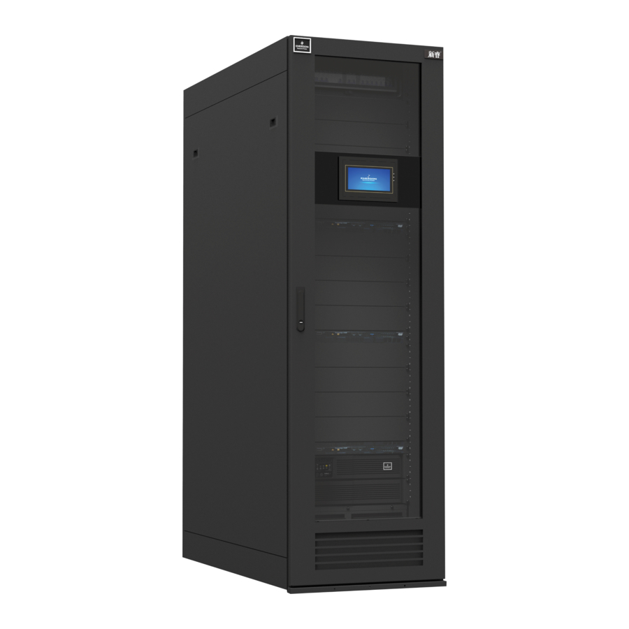
Chapter 1 Overview Chapter 1 Overview SmartCabinet integrated solution (SmartCabinet for short) is a datacenter solution produced by Vertiv Tech Co., Ltd.; it is applicable to the indoor environment such as miniature datacenter or office area. SmartCabinet is used to store the 19’’... -
Page 8: Features
The appearance and components of 600m-wide SmartCabinet standard product is shown in Figure 1-2. Figure 1-2 Appearance and components of 600m-wide standard unit The appearance and components of 800m-wide SmartCabinet standard product is shown in Figure 1-3. SmartCabinet Series Solution Product for IDC or Computer Rooms User Manual... -
Page 9: Functional Components
Figure 1-4 Appearance and components of 600m-wide integrated unit 1.5 Functional Components SmartCabinet product mainly includes the functional parts of cabinet, PMU distribution unit, UPS, air conditioner, emergent ventilation system, monitoring system, and local LCD screen. SmartCabinet Series Solution Product for IDC or Computer Rooms User Manual... - Page 10 Installed in a long air Air introduction channel to meet the heat Ensure that the cabinet exhaust air pressure Air introduction fan exchange air flow achieves performance requirements. system(used by requirement SmartCabinet Series Solution Product for IDC or Computer Rooms User Manual...
-
Page 11: Ambient Requirements
The storage environment requirements are listed in Table 1-4. Table 1-4 Storage environment requirements Item Requirement Storage environment Indoor, clean without dust Ambient humiduty 5%RH ~ 95%RH (Non-condensing) Ambient temperature -15° C ~ + 50° C SmartCabinet Series Solution Product for IDC or Computer Rooms User Manual... -
Page 12: Clearance
The space requirement of SmartCabient 600mm wide standard unit: Figure 1-6 Space requirement of 600mm wide standard unit The space requirement of SmartCabient 800mm wide standard unit: Figure 1-7 Space requirement of 800mm wide standard unit SmartCabinet Series Solution Product for IDC or Computer Rooms User Manual... -
Page 13: Weight-Bearing Capacity
If you cannot estimate the weight-bearing capacity, please consult the Vertiv office or service center. SmartCabinet Series Solution Product for IDC or Computer Rooms User Manual... -
Page 14: Chapter 2 Preliminary Before Installation
2. Lead the floating nut hook through the square hole, hitch the other fastener of the floating nut and pull it out to fix the fastener to the square hole completely, as shown in Figure 2-3. SmartCabinet Series Solution Product for IDC or Computer Rooms User Manual... -
Page 15: Fittings
Used to install the power distribution unit, monitoring system and user M6 panel screw equipment M6 pan head screw Used to connect and fix the frame Cable tie fixture kit Used to fix and bind the cables SmartCabinet Series Solution Product for IDC or Computer Rooms User Manual... -
Page 16: Accessories
The component with package is shown in Figure 2-4. See Table 2-6 for its ranges of dimensions and weight. SmartCabinet Series Solution Product for IDC or Computer Rooms User Manual... - Page 17 When the hand pallet truck or the electrical forklift is used to unload and carry them, it is recommended to forklift them on its center of gravity to avoid toppling over, as shown in Figure 2-6. SmartCabinet Series Solution Product for IDC or Computer Rooms User Manual...
- Page 18 2) Use a utility knife to cut off the packing strip on the package paper box carefully and remove the package paper box of the cabinet. 3) Use a utility knife to remove the extension film on the cabinet and the bagging package materials. SmartCabinet Series Solution Product for IDC or Computer Rooms User Manual...
- Page 19 1. When removing the pallet, you need to prepare the slope or similar device by yourself. 2. The whole cabinet is very heavy, so take precautions when pushing the cabinet from the pallet down to the ground along the slope, to avoid accidental collapse. SmartCabinet Series Solution Product for IDC or Computer Rooms User Manual...
-
Page 20: Installation Safety Instructions
5. When installing the SmartCabinet integrated unit, make sure that there are sufficient spaces for the air outlet and the air inlet of the cabinet. SmartCabinet Series Solution Product for IDC or Computer Rooms User Manual... -
Page 21: Chapter 3 Installation
3. Tighten the fixing nuts (shown in Figure 3-2) on the feet bolts counter clockwise, and the cabinet adjustment is completed. SmartCabinet Series Solution Product for IDC or Computer Rooms User Manual... -
Page 22: Installing Air Conditioner Of 600Mm Wide Standard Unit
2. In Figure 3-4, the two 1U-height supporting part of AC outdoor unit at lower part of the outdoor unit can be used as dummy plates in cold aisle of the cabinet. SmartCabinet Series Solution Product for IDC or Computer Rooms User Manual... -
Page 23: Installing Ac Outdoor Unit
1. Regular installation of outdoor unit (installed outdoor) 1) Place the outdoor unit on the base, as shown in Figure 3-7. 2) Use expansion bolts to fix the outdoor unit on the base. SmartCabinet Series Solution Product for IDC or Computer Rooms User Manual... - Page 24 AC outdoor unit on the top plate of the cabinet, as shown in Figure 3-9. SmartCabinet Series Solution Product for IDC or Computer Rooms User Manual...
-
Page 25: Connecting Copper Pipes
Table 3-1, please consult the manufacturer whether the pipe extension kit or replace thick pipe diameter copper pipe is needed. SmartCabinet Series Solution Product for IDC or Computer Rooms User Manual... - Page 26 The oil trap can store some frozen oil when the compressor stops. When the compressor starts up, the oil stored in the oil trap will be sucked into the compressor. Pipe connection port location SmartCabinet Series Solution Product for IDC or Computer Rooms User Manual...
- Page 27 1. The AC refrigerant is R410A. The low quality or counterfeit refrigerant will damage the system severely. Please use the refrigerant approved by Vertiv Tech Co., Ltd. For the system abnormity or damage caused by using other brands of refrigerant, the warranty will be invalid.
-
Page 28: Installing Air Conditioner Of 600Mm Wide Integrated Unit
2. Then open the internal cover, and the operating procedures are shown in Figure 3-14. You need to remove the two screws on the top of the cover and then push upward to remove the cover. SmartCabinet Series Solution Product for IDC or Computer Rooms User Manual... -
Page 29: Opening The Condenser Valve
If air conditioning equipment needs to add refrigerant, it is necessary to charge refrigerant on site. Read the nameplate for refrigerant information. Connect the vacuum valve and the filling port as shown in Figure 3-16. SmartCabinet Series Solution Product for IDC or Computer Rooms User Manual... -
Page 30: Connecting Drain Pipe Of Indoor Unit
5m. The drain pipe cannot be placed on frozen places, and it must be laid on the ground closely, moreover, the pipe cannot be higher than the tray outlet. SmartCabinet Series Solution Product for IDC or Computer Rooms User Manual... -
Page 31: Checklist After Installation
1. Remove the M4X10 screw (1PCS), push upward the original perforated board at the air outlet of the top frame body, remove the perforated board as shown in Figure 3-18. SmartCabinet Series Solution Product for IDC or Computer Rooms User Manual... - Page 32 4.The longest air duct supported by the system is 10m long with two elbow bends, and contact Vertiv service department if the length exceeds 10m. SmartCabinet Series Solution Product for IDC or Computer Rooms User Manual...
-
Page 33: Installing Smartcabniet Monitoring System
Make sure that the jumpers of MSC intelligent monitoring card are set to correct position. The jumper locations are shown in Figure 3-22. See Table 3-9 for the jumper setting of the MSC intelligent monitoring card. SmartCabinet Series Solution Product for IDC or Computer Rooms User Manual... -
Page 34: Installing Sensors
S04DIF Intelligent Digital Input Sensor With RJ45 Ports User Manual, IRM-S01W Water Leakage Detective Belt Sensor User Manual and G Net EDGE Wireless Network Card With USB Port User Manual. 2. The temperature sensor, 4DIF sensor has been pre-mounted in factory. SmartCabinet Series Solution Product for IDC or Computer Rooms User Manual... -
Page 35: Cable Connection
You only need to connect the cable between the UPS and the battery, and the UPS input and output cables (lines have been reserved on the ports). The system wiring diagram is shown in Figure 3-25: SmartCabinet Series Solution Product for IDC or Computer Rooms User Manual... -
Page 36: Connecting Msc Intelligent Monitoring Card Cables
COM1 port of MSC-C card, and connect the cable W12 (COM2) to the COM2 port of MSC-C card. Figure 3-26 Cable connection of COM port of MSC intelligent monitoring card SmartCabinet Series Solution Product for IDC or Computer Rooms User Manual... -
Page 37: Connecting Total Input Cable Of System
Lead the power cables through the cabling holes, connect the power cables to the power output cables of indoor unit, and use cable clamps to fix the cables, connect the other end to the AC power outside of the air conditioner system, as shown in Figure 3-28. SmartCabinet Series Solution Product for IDC or Computer Rooms User Manual... - Page 38 4) Inspection items after installation After the electrical installation is completed, the following requirements should be met: SmartCabinet Series Solution Product for IDC or Computer Rooms User Manual...
-
Page 39: Connecting Earth Cable
When earthing, use a M6 screw to fix one end of the earth cable on the earth hole, and lead the other end through the rubber protective ring on the bottom plate to the earth copper bar of the computer room. Earth hole Screw Cabinet A amplified Figure 3-31 Connecting earth cable SmartCabinet Series Solution Product for IDC or Computer Rooms User Manual... -
Page 40: Configure Communication Address And Port
3. This cabling box can also be installed in the front door of the 800mm wide standard unit, as shown in Figure 3-33. Figure 3-33 Cabling box of 800mm wide standard unit – Installation area of the front door of the cabinet SmartCabinet Series Solution Product for IDC or Computer Rooms User Manual... - Page 41 1. The U height space which is not occupied by equipment should be covered by the dummy panel. 2. After the cable layout is completed, use sealant to seal the used cable entry holes, to keep the cabinet be airtight. SmartCabinet Series Solution Product for IDC or Computer Rooms User Manual...
-
Page 42: Chapter 4 Commissioning Instructions
Check the fire Check and confirm the fire protection system stem node is normal access. Optional fighting System Check if the vacant space has been sealed by dummy plates. SmartCabinet Series Solution Product for IDC or Computer Rooms User Manual... -
Page 43: Startup And Commissioning
11. If an intelligent lock is selected, close the intelligent lock MCB, and you cannot close the cabinet door only after confirming the access control card can open the lock. SmartCabinet Series Solution Product for IDC or Computer Rooms User Manual... -
Page 44: System Commissioning
4. You can check whether the equipment enter the normal operation status via LCD. 5. After all the equipment run normally, you can start user server and other IT devices. SmartCabinet Series Solution Product for IDC or Computer Rooms User Manual... -
Page 45: Intelligent Lock Commissioning (Optional)
“System Homepage” -> “Security Management” ->“Access control management”->“Access control card management” to add a card number to the system and then click “Access control management”->“Authority management” to authorize the card. SmartCabinet Series Solution Product for IDC or Computer Rooms User Manual... -
Page 46: Firefighting Subrack (Optional)
Configurations of firefighting subrack You need to configure the firefighting module in the LCD: Select Menu-Configure in the LCD, and select the firefighting module and save as the picture in Figure 4-10. SmartCabinet Series Solution Product for IDC or Computer Rooms User Manual... -
Page 47: Power Off
5. Open the UPS input and output air breakers. 6. Open the total input air breaker on the PMU. 7. Check that all the equipment is powered off, and close all the doors of the cabinet. SmartCabinet Series Solution Product for IDC or Computer Rooms User Manual... -
Page 48: Chapter 5 Operation On Display Panel
Thermal management: The air supply temperature of the air conditioner uses a curve chart to display the data in the latest hour and the curve is refreshed every 6s; SmartCabinet Series Solution Product for IDC or Computer Rooms User Manual... - Page 49 Figure 5-4 Thermal management setting data screen, need a password to enter Figure 5-5 Thermal management setting data screen The control and setting operation has the second time confirmation function. SmartCabinet Series Solution Product for IDC or Computer Rooms User Manual...
-
Page 50: Power And Distribution
Figure 5-7 Power and distribution screen Each screen under PDU2 menu has the same display format as PDU1. Figure 5-8 PDU acquisition data screen in Power and distribution SmartCabinet Series Solution Product for IDC or Computer Rooms User Manual... -
Page 51: Environment Values
Figure 5-11 Environmental acquisition data screen Install the fire fighting subrack through clicking “Setting” -> “Configuring” interface, and the fire fighting subrack alarm status icon will be automatically displayed. SmartCabinet Series Solution Product for IDC or Computer Rooms User Manual... -
Page 52: Log
10s; If the backlight is off when the new alarm occurs, the alarm sound is turned off after 5min. Figure 5-14 Active alarm screen SmartCabinet Series Solution Product for IDC or Computer Rooms User Manual... -
Page 53: Setting
Password: Used to change the control authority through the local LCD display screen; You can operate via the Web pages of the SmartCabinet Intelligent monitoring unit, and can recover the password of the display screen to default password of “1234”; SmartCabinet Series Solution Product for IDC or Computer Rooms User Manual... - Page 54 Configuration: The default configuration of SmartCabinet is 5kUPS, one PDU; User can change the configuration to 3kUPS and two PDUs; After configuration, you need to wait for the SmartCabinet Intelligent monitoring unit to restart, and the waiting time is about 200s. SmartCabinet Series Solution Product for IDC or Computer Rooms User Manual...
- Page 55 Chapter 5 Operation On Display Panel Figure 5-21 Configuration screen SmartCabinet Series Solution Product for IDC or Computer Rooms User Manual...
-
Page 56: Chapter 6 Web Page Of Msc Intelligent Monitoring Unit
1. Double-click the icon of IE to run the software, click the menus of Tools -> Internet Options and then choose the Connections tab to pop up the window shown in Figure 6-2. SmartCabinet Series Solution Product for IDC or Computer Rooms User Manual... - Page 57 1. Double-click the icon of IE to run the software, click the menus of Tools -> Internet Options and then choose the Security tab to pop up the window shown in Figure 6-4. SmartCabinet Series Solution Product for IDC or Computer Rooms User Manual...
- Page 58 3. In the window shown in Figure 6-5, set ‘Medium-low’ for the security level. Click the Reset button to finish Reset custom settings, at last, click OK. 4. In the window shown in Figure 6-6, set Enable for File download. SmartCabinet Series Solution Product for IDC or Computer Rooms User Manual...
- Page 59 Figure 6-7 Enabling ActiveX controls 6. In the window shown in Figure 6-8, add the IP address of the MSC intelligent monitoring unit into the Trusted sites list. SmartCabinet Series Solution Product for IDC or Computer Rooms User Manual...
-
Page 60: Log In Msc Intelligent Monitoring Unit
If you forget the password, click the Forget Password button on the login page, and the screen will display the page of getting password, as shown in Figure 6-10. SmartCabinet Series Solution Product for IDC or Computer Rooms User Manual... -
Page 61: Homepage Of Msc Intelligent Monitoring Unit
4. Current number of every level alarm 5. Logo 6. [User] Logout 7. Real-time alarm displaying list 8. Alarm pop-out setting 9. Time calibrating link Figure 6-11 Homepage of MSC intelligent monitoring unit SmartCabinet Series Solution Product for IDC or Computer Rooms User Manual... - Page 62 Clicking the Setting button shown in Figure 6-12 enters setting status of the homepage, as shown in Figure 6-13. Figure 6-12 Setting button Figure 6-13 Setting page SmartCabinet Series Solution Product for IDC or Computer Rooms User Manual...
-
Page 63: Time Calibrating Link
For detailed operation, refer to Date/Time Setting in 6.4.7 System Options. Clearing Time-Out When there is no operation on the page within 15min, the page will become uncontrollable, as shown in Figure 6-16. SmartCabinet Series Solution Product for IDC or Computer Rooms User Manual... -
Page 64: Logout
When you click the specific device, the right part will display the relative information of the device, including Overview, Sampling, Control, Setting and Alarm. Overview Click the Overview tab, and click the Edit button, you can define the overview page, as shown in Figure 6-19. SmartCabinet Series Solution Product for IDC or Computer Rooms User Manual... - Page 65 Figure 6-20. Figure 6-20 Sampling signals If some signal is in alarm status, it will be displayed in red. The “Rear door status” signal as shown in Figure 6-20. SmartCabinet Series Solution Product for IDC or Computer Rooms User Manual...
- Page 66 Figure 6-23 Alarm signals You can set alarm level of several alarm signals at the same time, and at most 16 signals can be set at the same time for each time. SmartCabinet Series Solution Product for IDC or Computer Rooms User Manual...
-
Page 67: Ups Shutdown
3. UPS shutdown needs to reserve the shutdown time of about 10min for the servers connected to the UPS, so the shutdown time can be set to the time after 10min. SmartCabinet Series Solution Product for IDC or Computer Rooms User Manual... -
Page 68: Safe Management
Figure 6-28 Fire fighting alarm strategy Door Access Click the “Door Access” submenu in the “Safe Management” menu, the access control card management screen is popped up as shown in Figure 6-29. SmartCabinet Series Solution Product for IDC or Computer Rooms User Manual... - Page 69 Click the “History Events” to enter the history query screen to query the event log of the access control, as shown in Figure 6-31. Figure 6-31 History query Video management Click the video management sub-menu in safety management menu, the page as shown in Figure 6-32 will be displayed. SmartCabinet Series Solution Product for IDC or Computer Rooms User Manual...
- Page 70 2. Real time video Click the Real Time Video tab under the Video Management menu to display the page shown in Figure 6-34. Table 6-1 gives an icon description. SmartCabinet Series Solution Product for IDC or Computer Rooms User Manual...
- Page 71 Click the Video Playback tab under the Video Management menu. The page shown in Figure 6-35 will be displayed. Table 6-2 gives the corresponding icon description. Figure 6-35 Video playback SmartCabinet Series Solution Product for IDC or Computer Rooms User Manual...
- Page 72 As shown in Figure 6-38. Save up to the last 50 photos. The captured video can be viewed through the Video Playback tab under the Video Management menu. SmartCabinet Series Solution Product for IDC or Computer Rooms User Manual...
-
Page 73: Alarm Management
Index, Device Name, Signal Name, Alarm Level, Trigger valve, Start Date/Time, Confirmed by, Confirmed on Date/Time and End Date/Time, as shown in Figure 6-40. Click the Download button to download the query results. SmartCabinet Series Solution Product for IDC or Computer Rooms User Manual... - Page 74 3. When low level alarm is chosen, the alarm level above this level will also be chosen; 4. When some device is chosen, the highest level Critical Alarm will be chosen by default. Figure 6-41 Alarm notification configuration 2. SMS and Email Server Configuration SmartCabinet Series Solution Product for IDC or Computer Rooms User Manual...
- Page 75 3. Scheduled Notification Configuration Click the Alarm Notification submenu under the Alarm Management menu, and then click the Scheduled Notification Configuration tab, the page shown in Figure 6-43 pops up. SmartCabinet Series Solution Product for IDC or Computer Rooms User Manual...
- Page 76 As shown in Figure 6-44, the Key to Operator/Symbol list shows all the commands and their usages. Click the Add button to add new alarm linkage expression, as shown in Figure 6-45. SmartCabinet Series Solution Product for IDC or Computer Rooms User Manual...
-
Page 77: Data & History
4. All output signals can only be control signals, and the output signal value must be enumerated type Data & History The Data & History menu supplies query service of all types of historical data and logs for the user. SmartCabinet Series Solution Product for IDC or Computer Rooms User Manual... - Page 78 Click the History Data submenu under the Data & History menu, the page shown in Figure 6-49 pops up. The page has three tabs: History Report, Historical Curve, Curve Setting. Figure 6-49 History data 1. History Report SmartCabinet Series Solution Product for IDC or Computer Rooms User Manual...
- Page 79 Figure 6-51 Curve setting History Log Click the History Log submenu under the Data & History menu, the page shown in Figure 6-52 pops up. SmartCabinet Series Solution Product for IDC or Computer Rooms User Manual...
-
Page 80: Device Options
Device Address textbox turn gray and cannot be edited. When one kind of device has many models, you need to type the model ID, which must be numbers from 1 to xx. The model IDs under one kind of device must be different; SmartCabinet Series Solution Product for IDC or Computer Rooms User Manual... - Page 81 ⚫Modifying a device 1) Choose the device which needs to be modified in the device list; 2) Modify the device information; 3) Click the Modify button to make the setting effective; SmartCabinet Series Solution Product for IDC or Computer Rooms User Manual...
- Page 82 Figure 6-58 Confirming dialog box Click OK, the dialog box of Security authentication pops up, type the login password of current user, and click OK to uninstall the corresponding equipment type. SmartCabinet Series Solution Product for IDC or Computer Rooms User Manual...
- Page 83 Figure 6-60 Modify device name On the page shown in Figure 6-60, you can modify the device name. Type the new device name and click the Set button to make all setting effective. SmartCabinet Series Solution Product for IDC or Computer Rooms User Manual...
-
Page 84: System Options
Monitoring Unit The Monitoring Unit submenu is used to set the signals of MSC intelligent monitoring system, including Sampling, Setting and Alarm signals, the page is shown in Figure 6-63. SmartCabinet Series Solution Product for IDC or Computer Rooms User Manual... - Page 85 MSC intelligent monitoring system. 2. Access Management Click the Network Setting submenu under the System Options menu, and then click the Access Management tab, the page shown in Figure 6-65 pops up. SmartCabinet Series Solution Product for IDC or Computer Rooms User Manual...
- Page 86 4) Set the User Type: ‘Authenticated & Encrypted’, ‘Authenticated & Not Encrypted’, ‘Not Authenticated & Not Encrypted’; 5) Select Authentication Protocol: ‘MD5’, ‘SHA’; 6) Select Privacy Protocol: ‘DES’; 7) Self-define Authentication Password and Privacy Password. SmartCabinet Series Solution Product for IDC or Computer Rooms User Manual...
- Page 87 1) Type the self-defined customer name in the End-User textbox; 2) Choose the contactor for remote service in the Contact Person textbox, when the contactor is chosen, the corresponding mobile and email will be displayed; SmartCabinet Series Solution Product for IDC or Computer Rooms User Manual...
- Page 88 On the page shown in Figure 6-70, you can add user, modify user and delete user. ⚫Add user 1. Type username in the User Name textbox; 2. Choose the user authority; SmartCabinet Series Solution Product for IDC or Computer Rooms User Manual...
- Page 89 If users receive the test SMS and telephone, the test is successful; if not, the test fails, please check that the telephone number is correct and the SMS Modem is properly connected. SmartCabinet Series Solution Product for IDC or Computer Rooms User Manual...
- Page 90 Click the Restore System submenu under the System Options menu, the page shown in Figure 6-73 pops up. Figure 6-73 Restore System Click the Reboot SmartCabinet button to reboot the system. Click the Restore System button to restore all the default settings. SmartCabinet Series Solution Product for IDC or Computer Rooms User Manual...
- Page 91 On the page shown in Figure 6-75, click the Browse… button to download configure pack (.rdu file format) from the local catalogue, and then click the Install button to upgrade the system. Note The MSC intelligent monitoring system supports incremental upgrading function. SmartCabinet Series Solution Product for IDC or Computer Rooms User Manual...
-
Page 92: Help
The About SmartCabinet page displays Software Version, Serial Number and Identify Code of SmartCabinet, and supplies download links for User Manual and Tools, as shown in Figure 6-77. Figure 6-77 About SmartCabinet SmartCabinet Series Solution Product for IDC or Computer Rooms User Manual... -
Page 93: Chapter 7 Maintenance
To ensure the connectivity of IP address, you can use PING/ping command, and the method is as follows: icon at the lower left corner, and type ‘cmd’ in the 1) Click the extbox, as shown in Figure 7-1. SmartCabinet Series Solution Product for IDC or Computer Rooms User Manual... - Page 94 Q4: How to form a network of several SmartCabinet and perform centralized monitoring? A: The SmartCabinet supports connection to RDU-M centralized monitoring platform of Vertiv. See Figure 7-3 for the networking mode of several SmartCabinet. SmartCabinet Series Solution Product for IDC or Computer Rooms User Manual...
-
Page 95: Ac System Maintenance
Inspect water pan periodically for normal operation of the drain pipe. Ensure that no foreign matter or leakage exits in the drain pipe. 3. Outdoor unit maintenance 1) Refrigeration system SmartCabinet Series Solution Product for IDC or Computer Rooms User Manual... - Page 96 Refrigerant must be recycled in accordance with state and local regulations. 4. Maintenance inspection checklist Note Regular inspections are necessary to ensure proper operation of the AC unit. SmartCabinet Series Solution Product for IDC or Computer Rooms User Manual...
- Page 97 1. Refer to the following steps to manually modify the output power of the air conditioner compressor and fan to the given preset value in the system WEB page: a) Open the AC settings page on the WEB page (Figure 7-4) SmartCabinet Series Solution Product for IDC or Computer Rooms User Manual...
- Page 98 After the output of the compressor and fan is stable at the set value (about 10 minutes), read the “exhaust pressure measurement value” on the “Sampling” page (Figure 7-8), and perform the data in Table 7-2 for comparison, ensure that the pressure value error does not exceed 0.5 Bar. SmartCabinet Series Solution Product for IDC or Computer Rooms User Manual...
- Page 99 3) If the measured amount of refrigerant exceeds or falls below the recommended value, please contact Vettel technicians for treatment. 4) After completing the above test contents, and after the refrigerant supplement is completed, please exit the manual mode. SmartCabinet Series Solution Product for IDC or Computer Rooms User Manual...
-
Page 100: Ups Power Distribtuion System Maintenance
Check all closed doors and close them Door sensor alarm The door sensor is not installed well or Readjust the installation clearance or call the customer damaged service hotline of Vertiv SmartCabinet Series Solution Product for IDC or Computer Rooms User Manual... - Page 101 Check the actual thermal power of the equipment in the alarm Use in overload cabinet Low temperature Low temperature setpoint is unreasonable Reset the setpoint of low temperature alarm alarm SmartCabinet Series Solution Product for IDC or Computer Rooms User Manual...
-
Page 102: Appendix 1 System Distribution Diagram
Connect the distribution cables of each component of SmartCabinet system according to the silk printings of the PMU terminal block. 预留 空调 总输入 PDU2 PDU1 Future Extensiont Main Input UPS输出 UPS输入 预留输出 Input Output For Future Figure 2 Silk printings of the PMU terminal block SmartCabinet Series Solution Product for IDC or Computer Rooms User Manual... -
Page 103: Appendix 2 System Wiring Diagram
Appendix 2 System Wiring Diagram Appendix 2 System Wiring Diagram The schematic diagram of the SmartCabinet system distribution is shown in the following Figure. LAN USB COM1 COM2 RDU-C SmartCabinet Series Solution Product for IDC or Computer Rooms User Manual... -
Page 104: Appendix 3 Hazardous Substances List
X: Means the content of the hazardous substances in at least one of the average quality materials of the part is outside the limits specified in SJ/T11363-2006. Vertiv Tech Co., Ltd. has been committed to the design and manufacturing of environment-friendly products. It will reduce and eventually eliminate the harzardous substances in the products through unremitting efforts in research. However, limited by the... - Page 105 X: Means the content of the hazardous substances in at least one of the average quality materials of the part is outside the limits specified in SJ/T11363-2006. Vertiv Tech Co., Ltd. has been committed to the design and manufacturing of environment-friendly products. It will reduce and eventually eliminate the harzardous substances in the products through unremitting efforts in research. However, limited by the...
- Page 106 Communication 压缩机通讯 接线面板 CON1 EMI滤波板 室外风机 风机电容 U100 J78-485- 485- J78-485+ 485+ 高压开关 排气温度开关 J80-1 J66-GND J80-2 J66-EN U101U102U103 U V W 压缩机驱动器 BK BK BK 电抗器 电抗器 压缩机 SmartCabinet Series Solution Product for IDC or Computer Rooms User Manual...
Need help?
Do you have a question about the SmartCabinet Series and is the answer not in the manual?
Questions and answers