Table of Contents
Advertisement
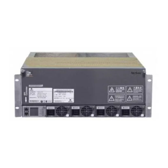
NetSure 731 A41 插框电源系统
用户手册
资料版本 V1.1
归档日期 2017-12-31
BOM 编码 31013139
维谛技术有限公司为客户提供全方位的技术支
持,用户可与就近的维谛技术有限公司办事处
或客户服务中心联系,也可直接与公司总部联
系。
维谛技术有限公司
版权所有,保留一切权利。内容如有改动,恕
不另行通知。
维谛技术有限公司
地址: 深圳市南山区学苑大道 1001 号南山智园
B2 栋
邮编:518055
公司网址:www.vertivco.com
客户服务热线:4008876510
E-mail:vertivc.service@vertivco.com
NetSure 731 A41 Subrack Power
System
User Manual
Version
V1.1
Revision date December 31, 2017
BOM
31013139
Vertiv Tech provides customers with technical
support. Users may contact the nearest Vertiv
local sales office or service center.
Copyright © 2017 by Vertiv Tech Co., Ltd.
All rights reserved. The contents in this document
are subject to change without notice.
Vertiv Tech Co., Ltd.
Address: Block B2, Nanshan I Park, No.1001
Xueyuan Road, Nanshan District, Shenzhen,
518055, P.R.China
Homepage: www.vertivco.com
E-mail: overseas.support@vertivco.com
Advertisement
Table of Contents

Related Manuals for Vertiv Tech NetSure 731 A41-S1


Summary of Contents for Vertiv Tech NetSure 731 A41-S1
- Page 1 Users may contact the nearest Vertiv 持,用户可与就近的维谛技术有限公司办事处 local sales office or service center. 或客户服务中心联系,也可直接与公司总部联 系。 Copyright © 2017 by Vertiv Tech Co., Ltd. 维谛技术有限公司 All rights reserved. The contents in this document 版权所有,保留一切权利。内容如有改动,恕 are subject to change without notice.
- Page 3 Safety Precautions To reduce the chance of accident, please read the safety precautions very carefully before operation. The "Caution, Notice, Warning, Danger" in this book do not represent all the safety points to be observed, and are only supplement to various safety points. Therefore, the installation and operation personnel must be strictly trained and master the correct operations and all the safety points before actual operation.
- Page 4 IV. ESD Notice The static electricity generated by the human body will damage the static sensitive elements on PCBs, such as large-scale ICs. Before touching any plug-in board, PCB or IC chip, ESD wrist strap must be worn to prevent body static from damaging the sensitive components.
- Page 5 Battery installation requires reliable grounding. And battery is connected before accessing the battery protection device. Others I. Sharp object Warning When moving equipment by hand, protective gloves should be worn to avoid injury by sharp object. II. Cable connection Notice Please verify the compliance of the cable and cable label with the actual installation prior to cable connection.
-
Page 7: Table Of Contents
Contents Chapter 1 Overview ................................1 1.1 Composition and Configuration ..........................1 Chapter 2 Installation Instruction ............................3 2.1 Safety Regulation ..............................3 2.2 Preparation ................................3 2.3 Mechanical Installation ............................4 2.4 Electrical Installation ............................. 6 2.4.1 Power System Cabling Method ......................... 6 2.4.2 Connecting AC Cables .......................... -
Page 9: Chapter 1 Overview
Chapter 1 Overview Chapter 1 Overview This chapter introduces model composition and configuration and features of NetSure 731A41-S1 and NerSure 731A41-S2 (abbreviated as 'power system' hereinafter). 1.1 Composition and Configuration Composition The power system is composed of power distribution、rectifier modules and controller module. Take NetSure731A41-S1 for example, the internal structure is shown as Figure 1-1. - Page 10 Chapter 1 Overview Configuration The configuration of the power system is listed in Table 1-1. Table 1-1 Configuration of power system Item NetSure 731 A41-S1 NetSure 731 A41-S2 NetSure 731 A41-S8 Controller Model:M225S Model:M221S/M222S Model:M830B Model: Model: Model: R48-3000e3 or R48-3000A3 or...
-
Page 11: Chapter 2 Installation Instruction
The equipment should be unpacked and inspected after it arrives at the installation site. The inspection shall be done by representatives of both the user and Vertiv Tech Co., Ltd. To inspect the equipment, you should open the packing case, take out the packing list and check against the packing list that the equipment is correct and complete. -
Page 12: Mechanical Installation
Chapter 2 Installation Instruction Table 2-3 DC load cable CSA selection Load route Max. output Min. cable Max cable length ( volt drop: 0.5V Max. cable Max cable length ( volt drop: 0.5V rated current current with min. CSA) with max. CSA) 16mm2 25mm2 10mm2... - Page 13 Chapter 2 Installation Instruction Subrack Power system power system M6 screw M6 screw Connector Connector Battery rack Battery bracket Figure 2-1 Cabinet and rack installation Installed in cabinet Insert the subrack power system to the matching cabinet, as shown in Figure 2-2. Power subrack 电源插框...
-
Page 14: Electrical Installation
Chapter 2 Installation Instruction Note 1. Tighten the captive screw of the MFU Panel by the cross head screwdriver when there is no operation. 2. Also tighten the handle by the cross head screwdriver. 3. Please plug in the new modules or installing a new panel after removing the rectifier module. 2.4 Electrical Installation 2.4.1 Power System Cabling Method Cabling from the top of the power system... -
Page 15: Connecting Ac Cables
Chapter 2 Installation Instruction Screw Cable-bunding plate (cabling area) Figure 2-6 Side cabling illustration 2.4.2 Connecting AC Cables Danger Danger 1. Switch off all MCBs and fuses before the electrical connection. 2. Only the qualified personnel shall do the power cable connection. Take the NetSure 731 A41-S1power system for example, the position of the connection terminals are shown in Figure 2-7. -
Page 16: Connecting Battery Cables
M225S.M225S controller and M225S1X user interface board cable connection is show in the following: Interface board Figure 2-10 NetSure 731 A41-S1 user interface board position illustration M225S controller provides two dry contact alarm output ports: DO1 and DO2. DO2 is for LLVD in subrack system. If LLVD is selected, it can't be used for dry contact and should be sealed by white tape when out of the factory . - Page 17 Chapter 2 Installation Instruction is not selected, It can be used for dry contact. NetSure 731 A41-S1 provides four extended dry contacts: DO3、DO4、 DO5 and DO6,the illustration is as shown in the following: Figure 2-11 M225S1X1usr interface board illustration Digital output dry contact specification of M225S controller and M225S1X1user interface board is as following: Digital output:relay isolation,max:30Vdc 1A,125Vac 0.5A,60W;Min:10uA@10Vdc.
- Page 18 Chapter 2 Installation Instruction The digital input ports of W2453X1 user interface board needs to connect active dry contact. Dry contact spec as following: Digital output: relay isolation, Max.:30Vdc/1A, 125Vac/0.5A, 60W; Min.: 10uA@10Vdc, alarm is definable. The functions of the interfaces are shown in Table 2-6. Table 2-6 Dry contacts definition Type Default alarm...
- Page 19 Chapter 2 Installation Instruction IB2 user interface board The external input and output signals are all connected to the IB2 user interface board. For the ports on the IB2 user interface board, see Figure 2-15. Digital inputs 1~ 8, Alarm output dry contact 20V ~ 60V I C port Address DIP...
- Page 20 Chapter 2 Installation Instruction Name of double-layer port Pin No. Pin name Definition DO2_COM Common contact of relay 2 DO1_NO NO contact of relay 1 DO2_NO NO contact of relay 2 DO3_NC NC contact of relay 3 DO4_NC NC contact of relay 4 DO3_COM Common contact of relay 3 DO4_COM...
- Page 21 Chapter 2 Installation Instruction 以太网口 Ethernet port RS232 communication RS232通讯串口 serial port Figure 2-15 M221S controller communication port The communication port of the M830B controller is shown in Figure 2-16. Figure 2-16 M830B controller communication port Please refer to Figure 2-17 to make communication signal cables. 接线表...
- Page 22 Chapter 2 Installation Instruction Temp terminal Figure 2-18 The position of temp terminal NetSure 731 A41 Subrack Power System User Manual...
-
Page 23: Chapter 3 Commissioning
Chapter 3 Commissioning Chapter 3 Commissioning The controllers can be used in the power system are M221S、M222S , M225S and M830B. The detail instructions of the controllers please refer to the user manuals. This section introduces commissioning after installation. During installation test, the corresponding safety rules should be adhered to. -
Page 24: Basic Settings
(The path to check and set of the M221S\M222S controller:SettingsBat. SettingsBasic Settings) NetSure 731 A41-S1:48V/SET;battery shunt coefficient:300A/25mV; (The path to check and set of the M225Scontroller:Settings Shunt A) NetSure 731 A41-S2:battery shunt coefficient:300A/25mV Setting controller according to number of battery groups connected. Default: two groups. -
Page 25: Alarm Check And System Operation Status Check
Chapter 3 Commissioning The User and password of the M830B controller is set by web, see NetSure™ Control Unit (NCU) User Manual Tabe 3-3 M830B controller paremeter settings Parameter Path Default settings LCD/ SettingsBatt SettingsChargeBatt1 Settings Rated Capacity 300Ah Rated Capacity LVD1 LCD/ Settings—LVD Settings—LVD1 Enabled... -
Page 26: Final Steps
Chapter 3 Commissioning ambient temperature. Hold the probe of the temperature sensor with hand and watch the controller which should display the change of temperature. 3.4 Final Steps Comments Make sure that materials irrelevants to the equipment have been all removed. ... -
Page 27: Chapter 4 Troubleshooting
Chapter 4 Troubleshooting Chapter 4 Troubleshooting This chapter describes the handling of alarms, as well as the routine maintenance of the system during system daily operation. The maintenance personnel must have adequate knowledge about the subrack power system. Note 1. - Page 28 Chapter 4 Troubleshooting Index Alarm Handling method 1. Check if the alarm is caused by mains failure, if yes, disconnect some loads to prolong the operation of the whole system. 2. Check the DC under-voltage value set through the controller. If the set value is inappropriate, correct it. DC Volt Low 3.
- Page 29 Chapter 4 Troubleshooting 2. Loosen the captive screw of the controller, as shown in Figure 4-2. Captive screw Figure 4-2 M225S Controller replacement (1) 3. Pull out the controller unit slowly until the J2 terminal is completely exposed, and pull out the connected terminals fromJ2,J6,J7 carefully and do insulation respectively.( as shown in Figure 4-3 ).
-
Page 30: Rectifier Fault Handling
Chapter 4 Troubleshooting 4.2 Rectifier Fault Handling Alarm handling The symptoms of usual rectifier faults include: power indicator ( green ) off, protection indicator ( yellow) on, protection indicator blink , fault indicator (red) on and fault indicator blink, the indicator locations as shown: Figure 4-5 Local Indicator Locations Table 4-2 Rectifier Troubleshooting Symptom... - Page 31 Chapter 4 Troubleshooting Note: Each rectifier module locks into a module mounting shelf by means of a latch located on the bottom of the module. The latch and rectifier module handle are interactive. Pushing the handle up into the module’s front panel causes the latch to extend to the locking position;...
-
Page 32: Rectifier Fan Replacement
Chapter 4 Troubleshooting Figure 4-6 Installing Rectifier 4.2.2 Rectifier Fan Replacement Each Rectifier uses a fan (P/N:32010485) for cooling. If fan replacement should become necessary, perform the following procedure. Refer to Figure 4-6 as this procedure is performed. WARNING! Warning In a system with NO redundant Rectifier, battery must have sufficient reserve to power the load(s) while the Rectifier is removed for fan replacement. - Page 33 Chapter 4 Troubleshooting 8. Replace the Rectifier into the shelf. Refer to the previous procedure for step-by-step instructions. 9. Enable the external alarms, or notify appropriate personnel that this procedure is finished. 10.Ensure that there are no local or remote alarms active on the system. Figure 4-7 Fan replacement NetSure 731 A41 Subrack Power System User Manual...
-
Page 34: Appendix 1 Technical And Engineering Data
Appendix 1 Technical And Engineering Data Appendix 1 Technical And Engineering Data Table 1 Technical data Parameter category Parameter Description -5℃~+40℃(derating is necessary above 40° C) Operating temperature -40℃~+70℃ Storage temperature Relative humidity 5%RH~95%RH Environmental ≤2000m(derating is necessary above 2,000m) Altitude Polution level Level 2... - Page 35 Appendix 1 Technical And Engineering Data Parameter category Parameter Description alarm point DC output under-voltage Default: -45.5 ± 0.2Vdc, 0.5Vdc higher than the under-voltage alarm point recovery point DC output over-voltage Default: -59.0 ± 0.2Vdc, configurable through controller DC output alarm and protection point protection Default: -44.0 ±...
- Page 36 Appendix 1 Technical And Engineering Data Parameter category Parameter Description Safety regulation Conform to IEC60950-1 standards ≤ 60db (A) (When the ambient temperature is lower than25° C) Acoustic noise At temperature of 15° C ~ 35° C and relative humidity not bigger than 90%RH, apply a test voltage of 500Vdc.
-
Page 37: Appendix 2 Installation Instruction Of Battery Rack
Appendix 2 Installation Instruction Of Battery Rack Appendix 2 Installation Instruction Of Battery Rack Installation Instruction Of Two-Layer And Four-Layer Battery Rack Packing list Accessory 1 Accessory 2 Accessory 3 Accessory 4 Accessory 5 Figure 1 Accessory Table 2 Packing list of the battery rack Battery rack Two-layer battery rack Four-layer battery rack... - Page 38 Appendix 2 Installation Instruction Of Battery Rack 3) Install accessory 2 and accessory 4 according to Figure 3. Accessory 4 Accessory 2 Figure 3 Installation procedure of accessory 2 and accessory 4 2. Installation procedures of four-layer battery rack 1) Install accessory 1, accessory 2 and accessory 3 according to Figure 2 (a) and Figure 2 (b). 2) Install accessory 5 according to Figure 4 (a).
-
Page 39: Installation Instruction Of Three-Layer Battery Rack
Appendix 2 Installation Instruction Of Battery Rack Installation Instruction Of Three-Layer Battery Rack Packing list Accessory 1 Accessory 2 Accessory 3 Accessory 4 Figure 5 Accessory Table 3 Packing list of the battery rack Accessory Accessory number Accessory 1 Accessory 2 Accessory 3 Accessory 4 Expansion bolt... -
Page 40: Fixing The Battery Rack
Appendix 2 Installation Instruction Of Battery Rack 3. Install accessory 2 and accessory 4 according to Figure 7. Accessory 2 Accessory 4 Figure 7 Installation procedure of accessory 2 and accessory 4 Fixing The Battery Rack 1. Fix the battery rack to the ground according to the installation dimensions shown in Figure 8. The fixing bolts are accessories. -
Page 41: Appendix 3 Wiring Diagram
5-4 W07 W2493ZX1 8-B- 11-KM1-2 18-J2-3 15-J7 7-J7-1 8-PL To the negative busbar of the module Note: Connet X4-1 and the cable of the temperature sensor. Figure 9 NetSure 731 A41-S1 wiring diagram NetSure 731 A41 Subrack Power System User Manual... - Page 42 Appendix 3 Wiring Diagram M34C3C1 DCSPD M2433X2 Front view LCU+ controller busbar socket M221S 9-BUS+-2 9-BUS+-1 Single-phase AC Front view X5-1 X6-1 input with the SPD W84 W84 W80 W80 User interface board 1 Front top view (open the panel) W2453X1 W2453X1 QFA2...
-
Page 43: Appendix 4 Schematic Diagram
Battery 1 C AN - QFB1 Battery 2 QFB2 QFA1 Main input Positive Busbar DCSPD DC Distribtion Unit C AN- CAN+ AC Distribtion Unit Figure 11 Schematic diagram of NetSure 731 A41-S1 NetSure 731 A41 Subrack Power System User Manual... - Page 44 Appendix 4 Schematic Diagram X6-1 X5-1 QFD1 QFD2 QFD3 KMD1 QFD8 2+ 2- 4+ 4- LLVD Contactor 1+ 1- 3+ 3- Controller M221S QFD9 1D12 QFD12 BLVD Contactor AC output W34C3C1 KMD2 QFA2 Terminal Class C SPD SPD1 Battery 1 CAN + CAN - QFB1...
Need help?
Do you have a question about the NetSure 731 A41-S1 and is the answer not in the manual?
Questions and answers