Table of Contents
Advertisement
Quick Links
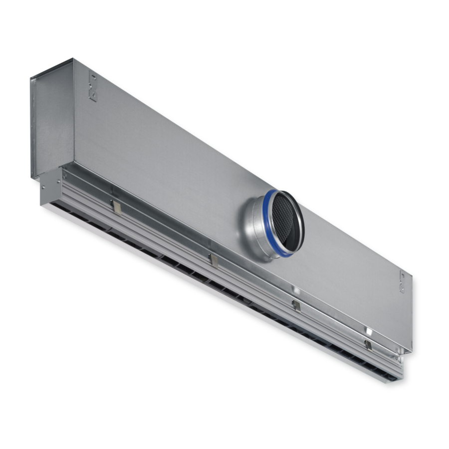
Product overview
Fig. 1: Schematic illustration of PL50-*-SF
①
Diffuser face (with 1- to 4‑slots)
②
Adjustable air control element
③
Screw fixing
④
End plate
⑤
End angle
⑥
Neck
Optional equipment: ③ ④ ⑤ ⑩ ⑪
Installation instructions
Air diffusers
Slot Diffusers Type PURELINE50
Air diffusers Slot Diffusers Type PURELINE50
GB/en
⑦
Plenum box
⑧
Suspension lug
⑨
Connector
⑩
Lip seal
⑪
Damper unit for volume flow rate balancing
TROX GmbH
Heinrich-Trox-Platz
47504 Neukirchen-Vluyn, Ger-
many
Germany
Phone: +49 (0) 2845 2020
Fax: +49 (0) 2845 202265
E-mail: trox@trox.de
http://www.troxtechnik.com
1
Advertisement
Table of Contents

Subscribe to Our Youtube Channel
Related Manuals for Trox Technik PURELINE50

Summary of Contents for Trox Technik PURELINE50
- Page 1 Adjustable air control element Suspension lug ③ ⑨ Screw fixing Connector ④ ⑩ End plate Lip seal ⑤ ⑪ End angle Damper unit for volume flow rate balancing ⑥ Neck Optional equipment: ③ ④ ⑤ ⑩ ⑪ Air diffusers Slot Diffusers Type PURELINE50...
-
Page 2: Important Notes
The appropriate protective equipment for a job must be worn for as long as the job takes. Air diffusers Slot Diffusers Type PURELINE50... -
Page 3: Transport And Storage
Sharp edges, sharp corners and thin sheet metal parts may cause cuts or grazes. – Be careful when carrying out any work. – Wear protective gloves, safety shoes and a hard hat. Air diffusers Slot Diffusers Type PURELINE50... -
Page 4: Technical Data
Fig. 2: Dimensions and spigot arrangement, * spigot arrangement for construction VS Fig. 3: Plenum box variants PL50-*-HS (symmetric position of plenum box, side entry spigot) PL50-*-HA (asymmetric position of plenum box, side entry spigot) PL50-*-VS (symmetric position of plenum box, top entry spigot) Air diffusers Slot Diffusers Type PURELINE50... - Page 5 229 + Y Neck extension Y = 0 / 22 / 47 / 72 / 97 / 121 Variant ØD [mm] C [mm] Fig. 6: PL50-4-DF/.../B00 PL50-1 Variant [mm] PL50-2 PL50-1 PL50-2 PL50-3 PL50-3 PL50-4 PL50-4 Air diffusers Slot Diffusers Type PURELINE50...
-
Page 6: Protective Equipment
Fig. 7: Position of plenum box If (L + 5) < L1, the plenum box can be positioned to the left, to the right or in the centre. Air diffusers Slot Diffusers Type PURELINE50... -
Page 7: Ceiling Installation
The supplied alignment plates (Fig. 9/1) help you align slot diffusers for a continuous linear arrangement. Fix an alignment plate (2 each per diffuser) on one side, then connect the next diffuser to it. Air diffusers Slot Diffusers Type PURELINE50... - Page 8 Fig. 13: Installation without extended border into a ceiling with rectangular panels; required length of installation opening when an end plate is used: L1 + 9 Fig. 11: EA end angle without and with extended border Air diffusers Slot Diffusers Type PURELINE50...
- Page 9 Fig. 15: Installation with extended border into a con- when an end angle is used: L1 + 29 tinuous ceiling; required length of installation opening when an end angle is used: L1 + 9 Air diffusers Slot Diffusers Type PURELINE50...
- Page 10 ④ in the plenum box. Using an Allen key (SW4) simplifies the fixing procedure. To remove the diffuser face, first remove the Allen screws (SW4 Allen key). Air diffusers Slot Diffusers Type PURELINE50...
- Page 11 Installation into continuous ceilings with spring clip fixing Fig. 18: Position of the spring, ceiling thickness up to 9 mm Ä ‘Diffuser Fig. 19: Position of the spring, ceiling thickness greater than 9 mm, installation dimensions faces’ on page 5 Air diffusers Slot Diffusers Type PURELINE50...
- Page 12 600 - 1350 – 1500 1650 1800 1950 Duct connection The plenum box has a spigot for duct connection. Variants with a double lip seal allow for a sufficiently tight connection; additional sealing is not required. Air diffusers Slot Diffusers Type PURELINE50...
- Page 13 Fig. 22: Setting the damper blade, e.g. with a screwdriver Setting the air discharge direction These are only schematic diagrams to illustrate the setting of the air control elements. Air diffusers Slot Diffusers Type PURELINE50...
- Page 14 Alternating air control elements set to left-hand or right-hand air discharge Alternating angled air discharge Alternating air control elements set to left-hand or right-hand air discharge Vertical air discharge One-way horizontal air discharge to the left Air diffusers Slot Diffusers Type PURELINE50...
- Page 15 Do not use cleaning agents that contain chlorine. Do not use equipment for removing stubborn contamination, e.g. scrubbing sponges or scouring cream, as it may damage the sur- faces. Air diffusers Slot Diffusers Type PURELINE50...
- Page 16 Air diffusers Slot Diffusers Type PURELINE50...
Need help?
Do you have a question about the PURELINE50 and is the answer not in the manual?
Questions and answers