Table of Contents
Advertisement
Advertisement
Table of Contents

Related Manuals for Lowrance ActiveTarget


Summary of Contents for Lowrance ActiveTarget
- Page 1 ActiveTarget™ INSTALLATION MANUAL ENGLISH www.lowrance.com...
- Page 3 Copyright © 2020 Navico Holding AS. Warranty The warranty card is supplied as a separate document. In case of any queries, refer to the brand website of your unit or system: www.lowrance.com Compliance statements Declarations The relevant declarations of conformity are available at: www.lowrance.com...
- Page 4 Navico® is a trademark of Navico Holding AS. • Lowrance® is a trademark of Navico Holding AS. • ActiveTarget™ is a trademark of Navico Holding AS. About this manual Important text that requires special attention from the reader is emphasized as follows: ¼...
-
Page 5: Table Of Contents
Contents Parts included Sonar module installation Mounting guidelines Installation 10 Transducer installation 10 Shaft mounting 16 Motor mounting 20 Wiring 20 Guidelines 21 Wiring overview 22 Transducer 23 Ethernet 24 Power 27 Grounding 27 LED indicators 28 Dimensional drawings 28 Sonar module 29 Transducer 30 Technical specification 30 Sonar module... -
Page 6: Parts Included
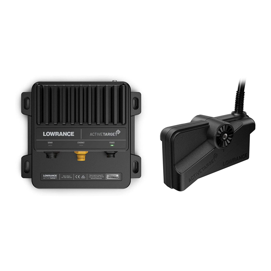
Parts included Parts included| Installation Manual... - Page 7 A ActiveTarget transducer B Sonar module mounting screws C M4 sonar module grounding screw D Sonar module E Ethernet cable F Power cable G M6x20 cap screw, 4x H Trolling motor shaft collar back (shaft mount) Rubber collar inserts, 2x...
-
Page 8: Sonar Module Installation
Sonar module installation This chapter describes how to install the sonar module. Mounting guidelines Choose the mounting location carefully, make sure that there are no hidden electrical wires or other parts behind the panel before you drill or cut. Ensure that any cutting or drilling is done in a safe position and will not weaken the boat’s structure. -
Page 9: Installation
Installation Mark the screw locations using the module as a template, and drill pilot holes. Secure the module using fasteners that are suitable for the material you are mounting the module to. Sonar module installation | Installation Manual... -
Page 10: Transducer Installation
Transducer installation This chapter describes how to install the transducer. The transducer can be mounted either to the shaft or to the motor of the trolling motor. Shaft mounting The transducer can be oriented in three different ways; down looking, forward looking, or in scout position. Down Forward Scout... - Page 11 Forward: Use for seeing fish and structure directly in front of the transducer. Know the depth of the fish and structure to target your next cast. Scout: Use to scan large areas for fish and structure. Search for schooling fish and know the direction of your next cast. Attach the bracket arm to the shaft front collar Install the bracket arm in the desired position to the shaft collar.
- Page 12 Scout orientation Align and attach the shaft clamp Align the shaft bracket with the centerline of the trolling motor. 12 | Transducer installation| Installation Manual...
- Page 13 Down orientation | 13 Transducer installation | Installation Manual...
- Page 14 Forward orientation 14 | Transducer installation| Installation Manual...
- Page 15 Scout orientation | 15 Transducer installation | Installation Manual...
-
Page 16: Motor Mounting
Motor mounting The transducer can be oriented in three different ways on most motors; down looking, forward looking, or in scout position. Down Forward Scout The transducer can be mounted on the port or starboard side of the shaft. Port side Starboard side Down: Use for vertical fishing to see what is below the transducer. - Page 17 Down orientation Attach the bracket to the transducer. Secure the assembly to the motor using the hose clamp. The hose clamp should be tightened just enough to prevent the transducer from moving during normal use. Then orient the transducer to the down orientation by firmly gripping and rotating the transducer until the alignment marks are aligned.
- Page 18 Forward orientation Attach the bracket to the transducer. Secure the assembly to the motor using the hose clamp. The hose clamp should be tightened just enough to prevent the transducer from moving during normal use. Then orient the transducer to the forward orientation by firmly gripping and rotating the transducer until the alignment marks are aligned.
- Page 19 Scout orientation Attach the transducer to the scout bracket arm. Then install the transducer and bracket arm to the bracket. Secure the assembly to the motor using the hose clamp. The orientation can be adjusted by firmly gripping and rotating the transducer until the alignment marks are aligned.
-
Page 20: Wiring
Wiring This chapter describes how to wire the sonar system. Guidelines Do not: • Make sharp bends in the cables. • Run cables in a way that allows water to flow down into the connectors. • Run the data cables adjacent to radar, transmitter, or large/high current carrying cables or high frequency signal cables. -
Page 21: Wiring Overview
Wiring overview Sonar module Grounding Transducer Battery Ethernet | 21 Wiring | Installation Manual... -
Page 22: Transducer
Transducer Leave enough slack in the cable so the transducer can be adjusted to all possible orientations (Forward/Down/Scout). There also needs to be enough slack in the cable loop so that the motor shaft can spin all the way around without damaging the cable. Connect the transducer to the sonar port of the module. -
Page 23: Ethernet
Ethernet Connect the Ethernet cable to the Ethernet port of the module. The other end should be connected to your display unit or Ethernet expansion device. Ethernet | 23 Wiring | Installation Manual... -
Page 24: Power
Power The unit is designed to be powered by a 12 or 24 V DC system. It is protected against reverse polarity, under voltage, and over voltage (for a limited duration). A fuse or circuit breaker should be fitted to the positive supply. For recommended fuse rating, refer to “Technical specification”... - Page 25 12/24 V DC Description Color Not used Blue Accessory wake up Yellow + 12 V DC DC Negative Black Fuse Switch Power controlled by power bus/display unit The unit will turn ON/OFF when power is applied/removed. By connecting the yellow wire to a display unit’s yellow wire, the sonar module will turn on the moment the display unit is powered up.
- Page 26 12/24 V DC Description Color Not used Blue Accessory wake up Yellow + 12 V DC DC Negative Black Fuse 26 | Wiring| Installation Manual...
-
Page 27: Grounding
Grounding The grounding terminal is DC isolated from power to eliminate the risk of galvanic corrosion. For installations that suffer from noise issues, the grounding terminal allows for the option to connect to various possible ground points. The grounding point can be the vessel’s bonded ground/earth, non bonded RF Ground, or battery minus (DC negative). -
Page 28: Dimensional Drawings
Dimensional drawings Sonar module 219.3 mm (8.63”) 197.3 mm (7.76”) 115.48 mm 192.1 mm (4.54”) (7.56”) 175.1 mm (6.89”) 72.9 mm (2.86”) 28 | Dimensional drawings| Installation Manual... -
Page 29: Transducer
Transducer 7.62 m (25 ft) 82.4 mm (3.24”) 149.8 mm 58.0 mm (5.90”) (2.28”) | 29 Dimensional drawings | Installation Manual... -
Page 30: Technical Specification
Technical specification Sonar module Environmental Storage temperature -30°C to +70°C (-22°F to +158°F) Operating temperature -15°C to +55°C (5°F to 131°F) IP class IP67 Electrical Power supply 12/24 V DC Operating voltage 10.8 V DC - 31.2 V DC Current drain 1.5A at 13.8 V (maximum) Reverse polarity... -
Page 31: Transducer
Transducer Environmental Storage temperature -30°C to +70°C (-22°F to +158°F) Water temperature for 0°C to +35°C operation (32°F to +95°F) Physical Weight 1.21 kg (2.67 lbs) Cable length 7.62 m (25 ft) Mounting options Trolling motor shaft Trolling motor lower unit Transom mount (sold separately) | 31 Technical specification |... - Page 33 ®Reg. U.S. Pat. & Tm. Off, and ™ common law marks. Visit www.navico.comintellectual-property to review the global trademark www.lowrance.com rights and accreditations for Navico Holding AS and other entities.
Need help?
Do you have a question about the ActiveTarget and is the answer not in the manual?
Questions and answers
Need schematic on how to tape active target cable to ghost trolling motor shaft and cable
Can I order only part # H on the Active Target pole mount It is listed on page 6 And what is the price Thanks