Table of Contents
Advertisement
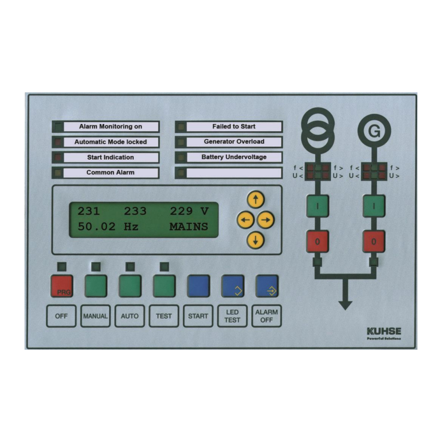
Service Manual
for product: KEA 201 SPL:
Power Control Unit for Emergency and
Peak Load Gensets with overlapping Synchronisation
File: SA_KEA 201 SPL_EN_Ver 2016-07-01 (replaces Version 2014-12-19)
_____________________________________________________________________________________
1.
Design
The control unit is incorporate into the front door of the switchboard. When installed, the front meets the
protection class IP 44. The two rows of LEDs are marked with interchangeable labels. The relay units
are mounted on the mounting plate and linked to the control unit in the door with the supplied cable.
The control unit has an optical fibre and a USB interface for the connection of a PC. Only one of them can
be used at a time
1.1.
Parameterisation
With the parameterisation software P
readouts are possible.
1. Additional Interface CAN
2. Additional Parameters
3. Alarm Remote Erasure
4. Alarms
5. Analogue Inputs
6. Analogue Outputs
7. Battery Monitor
8. CAN 0
9. Frequency Controller at isolated Operation
10. Generator Current Monitor
11. Generator Voltage Monitor
12. Hardware
13. Internal Synchroniser
14. J1939 engine management
Parameterisation can also be performed at the display.
_________________________________________________________________________________
Alfred Kuhse GmbH
An der Kleinbahn 39, D-21423
Winsen (lu(
W
, the following settings (password-protected) and analogue
ARA
IN
Phone: +49 4171-798-0
Fax +49 4171-798-117
15. J1939 Hide analogue values
16. Load Controller
17. Mains Voltage Monitor
18. Modem
19. Power Factor Controller
20. ProMerk. programmable Flags
21. Reference Load Regulation
22. Relay and Indicator Functions
23. Speed Monitoring and Control
24. Sprinkler Operation
25. Starting and Stopping
26. Transfer Mains – Generator
27. VDE-AR-N 4105 Protection for Parallel Operation
28. Voltage Controller
kuhse@kuhse.de
Changes without further notice reserved.
www.kuhse.de
Advertisement
Table of Contents

Related Manuals for Kuhse KEA 201 SPL


Summary of Contents for Kuhse KEA 201 SPL
-
Page 1: Design
Service Manual for product: KEA 201 SPL: Power Control Unit for Emergency and Peak Load Gensets with overlapping Synchronisation File: SA_KEA 201 SPL_EN_Ver 2016-07-01 (replaces Version 2014-12-19) _____________________________________________________________________________________ Design The control unit is incorporate into the front door of the switchboard. When installed, the front meets the protection class IP 44. -
Page 2: Analogue Readouts
Service Manual for KEA 201 SPL – File: SA_KEA 201 SPL_EN_Ver 2016-07-01.doc 2 / 26 2 / 26 1.2. Analogue Readouts Actual values: - Mains: Voltages and frequencies - Generator: voltages, frequencies, current, active and apparent power, PF (for L2) -
Page 3: Table Of Contents
Service Manual for KEA 201 SPL – File: SA_KEA 201 SPL_EN_Ver 2016-07-01.doc 3 / 26 3 / 26 Contents Design ................................ 1 1.1. Parameterisation ..........................1 1.2. Analogue Readouts ..........................2 Amendments ............................. 2 Contents ..............................3 Safety Instructions ........................... 5 4.1. - Page 4 Service Manual for KEA 201 SPL – File: SA_KEA 201 SPL_EN_Ver 2016-07-01.doc 4 / 26 4 / 26 13. Enabling Mains Parallel Operation ....................... 13 13.1. Description ............................13 13.2. Setpoint for Power ..........................14 14. Mains Recovery in Peak Load Operation ..................... 14 15.
-
Page 5: Safety Instructions
Service Manual for KEA 201 SPL – File: SA_KEA 201 SPL_EN_Ver 2016-07-01.doc 5 / 26 5 / 26 Safety Instructions 4.1. Regulations and Instructions 1. The relevant regulations, especially the VDE regulations, must be observed. 2. The device must be parameterised in such a way that any risk to persons or property is prevented. -
Page 6: Operating The Display
Service Manual for KEA 201 SPL – File: SA_KEA 201 SPL_EN_Ver 2016-07-01.doc 6 / 26 6 / 26 The following signals (if needed) are directly applied to the control unit: Voltage of mains and generator Current of generator ... -
Page 7: Pin Number, Ident-Number
Service Manual for KEA 201 SPL – File: SA_KEA 201 SPL_EN_Ver 2016-07-01.doc 7 / 26 7 / 26 PIN Number, Ident-Number To modify a parameter, you first have to enter the relevant I . This number is compared DENT UMBER with the PIN , and if they are identical, the user is authorised to parameterise the device. -
Page 8: Alarm Monitoring
Service Manual for KEA 201 SPL – File: SA_KEA 201 SPL_EN_Ver 2016-07-01.doc 8 / 26 8 / 26 Group Function Section in FUNCTIONS AND PARAMETERISATION Encoding of alarms Alarm Monitoring Mains voltage monitor Voltage Monitor Mains failure protection Mains failure monitoring in parallel operation... -
Page 9: Alarm Announcing And Acknowledgement
Service Manual for KEA 201 SPL – File: SA_KEA 201 SPL_EN_Ver 2016-07-01.doc 9 / 26 9 / 26 At terminal inputs, an alarm is triggered when the corresponding signalling switch closes (normally open, make contact) or opens (normally closed, break contact). In case of analogue signals an alarm... -
Page 10: Battery Voltage Monitor
Service Manual for KEA 201 SPL – File: SA_KEA 201 SPL_EN_Ver 2016-07-01.doc 10 / 26 10 / 26 8.3.6. Battery voltage Monitor A relay (with a break function) can be programmed for the direct output of the battery voltage monitor. -
Page 11: Pf Controller Failure
Service Manual for KEA 201 SPL – File: SA_KEA 201 SPL_EN_Ver 2016-07-01.doc 11 / 26 11 / 26 8.3.16. PF controller failure An alarm is indicated when after a pre-set time the actual PF has not matched the pre-set PF (the actual PF has to be at least once inside the dead zone). -
Page 12: Sealing The Setpoints
Service Manual for KEA 201 SPL – File: SA_KEA 201 SPL_EN_Ver 2016-07-01.doc 12 / 26 12 / 26 9.3. Sealing the Setpoints Inside the KEA, on the middle PCB – see further below – you will find a jumper. If you... -
Page 13: Peak Load Operation Mode
Service Manual for KEA 201 SPL – File: SA_KEA 201 SPL_EN_Ver 2016-07-01.doc 13 / 26 13 / 26 Peak Load Operation Mode 1. The genset is started by a peak load command. If the genset is already running in mode, TEST the system switches to parallel operation. -
Page 14: Setpoint For Power
Service Manual for KEA 201 SPL – File: SA_KEA 201 SPL_EN_Ver 2016-07-01.doc 14 / 26 14 / 26 In M parallel operation (i.e. no peak load command) the generator voltage monitor will also ANUAL switch over to the VDE-specified thresholds. For the VDE-AR-N 4105, these are:... -
Page 15: Controlling Reactive Power
Service Manual for KEA 201 SPL – File: SA_KEA 201 SPL_EN_Ver 2016-07-01.doc 15 / 26 15 / 26 If the frequency decreases, the power is increased according to the specified gradient until it reaches the level at 51.5 Hz. If the frequency still decreases, the genset can be operated with the enabled power level. In this case, an increase in power will occur in steps of 10 % of the enabled power per minute. -
Page 16: Terminal 16: Feedback Signal: Generator Cb Is Off
Service Manual for KEA 201 SPL – File: SA_KEA 201 SPL_EN_Ver 2016-07-01.doc 16 / 26 16 / 26 Terminal 16: Feedback signal: G ENERATOR IS OFF An auxiliary contact (NC) of the generator CB (or contactor) is connected to this terminal. It shows the position of the breaker. -
Page 17: Terminal 27: Power Control In Peak Load Operation
Service Manual for KEA 201 SPL – File: SA_KEA 201 SPL_EN_Ver 2016-07-01.doc 17 / 26 17 / 26 Terminal 27: Power Control in Peak Load Operation. A signal on minus enables 30 % (parameterisable) of the peak load. In combination with terminal 28, 100 % is enabled. - Page 18 Service Manual for KEA 201 SPL – File: SA_KEA 201 SPL_EN_Ver 2016-07-01.doc 18 / 26 18 / 26 Speed of frequency controller lower 3702 ProMerk, output of AND-4 6108 Speed of frequency controller higher 3704 ProMerk, output of AND-5 6110...
- Page 19 Service Manual for KEA 201 SPL – File: SA_KEA 201 SPL_EN_Ver 2016-07-01.doc 19 / 26 19 / 26 Voltage of cos phi / PF controller lower 4740 Optional module CANOpen, Input 15 0940 Voltage of cos phi / PF controller higher...
-
Page 20: Technical Data
CAN bus interface to Engine Control Unit (ECU); the protocol must be known and implemented 20.6. Connection to other Systems (optional) Device for attachment on a mounting rail: KNG (Kuhse Network Gateway) to connect to other systems via Profibus DP or Modbus RTU _________________________________________________________________________________... -
Page 21: Diagrams
Service Manual for KEA 201 SPL – File: SA_KEA 201 SPL_EN_Ver 2016-07-01.doc 21 / 26 21 / 26 Diagrams 21.1. Response Diagram for Thermal Overload ______________________________________________________________________________________ Alfred Kuhse GmbH Phone: +49 4171-798-0 kuhse@kuhse.de Changes without further notice An der Kleinbahn 39, D-21423 Fax +49 4171-798-117 www.kuhse.de... -
Page 22: Connection Diagram, Rz-071-D
Service Manual for KEA 201 SPL – File: SA_KEA 201 SPL_EN_Ver 2016-07-01.doc 22 / 26 22 / 26 21.2. Connection Diagram, RZ-071-D ______________________________________________________________________________________ Alfred Kuhse GmbH Phone: +49 4171-798-0 kuhse@kuhse.de Changes without further notice An der Kleinbahn 39, D-21423 Fax +49 4171-798-117... -
Page 23: Connection Diagram, Rz-071-E (Optional)
Service Manual for KEA 201 SPL – File: SA_KEA 201 SPL_EN_Ver 2016-07-01.doc 23 / 26 23 / 26 21.3. Connection Diagram, RZ-071-E (optional) 21.4. Connection Diagram, KEA 201 SPL ______________________________________________________________________________________ Alfred Kuhse GmbH Phone: +49 4171-798-0 kuhse@kuhse.de Changes without further notice... -
Page 24: Connections, Analogue Inputs
Service Manual for KEA 201 SPL – File: SA_KEA 201 SPL_EN_Ver 2016-07-01.doc 24 / 26 24 / 26 21.5. Connections, analogue Inputs 21.6. Door Cross Section of KEA, Frontview ______________________________________________________________________________________ Alfred Kuhse GmbH Phone: +49 4171-798-0 kuhse@kuhse.de Changes without further notice... -
Page 25: Controller Pcb With Jumper For Sealing Setpoints
Service Manual for KEA 201 SPL – File: SA_KEA 201 SPL_EN_Ver 2016-07-01.doc 25 / 26 25 / 26 21.7. Controller PCB with Jumper for Sealing Setpoints ______________________________________________________________________________________ Alfred Kuhse GmbH Phone: +49 4171-798-0 kuhse@kuhse.de Changes without further notice An der Kleinbahn 39, D-21423 Fax +49 4171-798-117 www.kuhse.de... -
Page 26: Drilling Template, Scale 1:1 - Print Without Scaling
Service Manual for KEA 201 SPL – File: SA_KEA 201 SPL_EN_Ver 2016-07-01.doc 26 / 26 26 / 26 Drilling Template, Scale 1:1 – print without scaling! _________________________________________________________________________________ Alfred Kuhse GmbH Phone: +49 4171-798-0 kuhse@kuhse.de Changes without further notice reserved. An der Kleinbahn 39, D-21423 Fax +49 4171-798-117 www.kuhse.de...
Need help?
Do you have a question about the KEA 201 SPL and is the answer not in the manual?
Questions and answers