Table of Contents
Advertisement
Advertisement
Table of Contents

Related Manuals for Thytronic XMR-D


Summary of Contents for Thytronic XMR-D
- Page 1 XMR-D GROUP “4I+4V+(4I+64F)” MANUAL XMR-D EQUIPMENT MANUAL Ed. 2.9 - 02/2021...
- Page 2 INTENTIONALLY BLANK PAGE XMR-D EQUIPMENT MANUAL Ed. 2.9 - 02/2021...
- Page 3 100% stator earth fault with 3rd harmonic (27H - 59H) ..........................24 Directional active overpower 32P ................................24 Directional reactive overpower 32Q ................................25 Undercurrent - 37 ......................................25 Directional active underpower 37P ................................25 Directional reactive underpower 37Q ................................26 XMR-D EQUIPMENT MANUAL Ed. 2.9 - 02/2021...
- Page 4 Development tool (Builder) ..................................54 4.3 I/0 DESCRIPTION ......................................55 Metering inputs ......................................55 Conventions ........................................60 Use of measured signals ..................................... 63 Binary inputs ........................................64 Output relays ......................................... 70 LED indicators ........................................71 Communication interfaces ...................................75 XMR-D EQUIPMENT MANUAL Ed. 2.9 - 02/2021...
- Page 5 Delayed inputs ......................................358 Self test ........................................358 Pilot wire diagnostic ....................................359 Selective Block - BLOCK2 ..................................359 Fault recording - SFR ....................................359 Event recording - SER ....................................359 Oscillography - DFR ....................................359 XMR-D EQUIPMENT MANUAL Ed. 2.9 - 02/2021...
- Page 6 — 8 APPENDIX 8.1 APPENDIX A1 - INPUT-OUTPUT SCHEME..............................378 8.2 APPENDIX A2 - PROTECTION FUNCTIONS ............................... 379 8.3 APPENDIX A3 - APPLICATION SCHEMES ..............................380 8.4 APPENDIX B - EC Conformity Declaration ..............................384 XMR-D EQUIPMENT MANUAL Ed. 2.9 - 02/2021...
- Page 7 This document contains the description of all the protection functions present in the versions XMR-A, XMR-V, XMR-P, XMR-D and XMR-T; for the functions actually present in the single ones versions refer to the table on the following page.
- Page 8 Multiple Profiles (A, B, C, D) Work in Progress Threshold key n (1,2) - m (1,2,3,4,5,6) - p (1,2,3) - q (1,2,3,4) - w (1,2,3,4,5) Standard Optional with requested SW Package Optional with requested HW Expansion XMR-D EQUIPMENT MANUAL INTRODUCTION Ed. 2.9 - 02/2021...
- Page 9 Note 1 The rating data can be found on labels on the back and on the front (accessible after removing the left frame) Note 2 The rating data can be found on labels on the front plate (accessible after removing the right frame) XMR-D EQUIPMENT MANUAL INTRODUCTION...
- Page 10 The declared values for the overshoot time are applicable with the lower setting value of the operation time. XMR-D EQUIPMENT MANUAL INTRODUCTION Ed. 2.9 - 02/2021...
- Page 11 OR and NOR logic gates ≥1 ≥1 EXOR logic gate Flip Flop set-dominant INPUT ON delay timer with reset ( delay) OUTPUT RESET RESET INPUT ON delay timer without reset ( delay) OUTPUT Symbols.ai XMR-D EQUIPMENT MANUAL INTRODUCTION Ed. 2.9 - 02/2021...
- Page 12 RESET INPUT Minimum pulse width operation for output relays ( OUTPUT INPUT Latched operating mode for output relays and LEDs Latched OUTPUT INPUT Pulse operating mode for output relays OUTPUT Symbols1 .ai XMR-D EQUIPMENT MANUAL INTRODUCTION Ed. 2.9 - 02/2021...
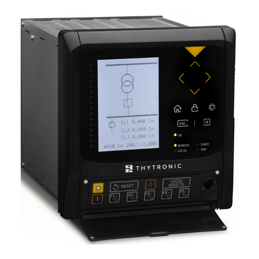
- Page 13 The methods of calibration, programming and reading of the measurements and recordings can be implemented through Personal Computer with Software support ( ThyVisor) or via bus RS485 or Ether- net communication; all the above operations are possible using the keyboard frontal view (MMI). Photo — XMR-D EQUIPMENT MANUAL GENERAL Ed. 2.9 - 02/2021...
- Page 14 ◊ Module 8 PT100 (XMPT) ◊ Module 32 Digital Inputs (XMID32) ◊ Module 16 Digital Outputs (XMR16) ◊ Module 6 Analogue Outputs 4÷20mA (XMCI) ◊ Rotor-Ground Protection Module (XMR-P and XMR-D ONLY) XMR-D EQUIPMENT MANUAL GENERAL Ed. 2.9 - 02/2021...
- Page 15 CID sending, etc. are routed via the “SSH” protocol, in encrypted mode. Data exchange protocols with the SCADA, e.g. IEC61850 / DNP3 / MODBUSTCP are unencrypted, if IEC62351 specification is not expressly requested. The synchronization protocols NTP, PTP are normally unencrypted. XMR-D EQUIPMENT MANUAL GENERAL Ed. 2.9 - 02/2021...
- Page 16 The RADIUS authentication as a reference to a remote server and uses a shared secret between card and server for validation of access requests. The configurator provides the possibility to define all parameters necessary for this authentication mode. XMR-D EQUIPMENT MANUAL GENERAL Ed. 2.9 - 02/2021...
- Page 17 — Mounting: • Flush • Rack External dimensions Basic version (XMR-A, XMR-V, XMR-P) 171 x 178 x 246 (H/W/D) External dimensions Basic version (XMR-D, XMR-T) 243 x 178 x 246 (H/W/D) Terminals screw connection Mass (XMR-A, XMR-V, XMR-P) 4.5 kg Mass (XMR-D, XMR-T) 5.5 kg...
- Page 18 IEC 60255-27 Pollution degree Reference voltage 250 V Overvoltage category — Certifications Product standards EN 50263 CE Conformity • EMC Directive 2014/30/EC • Low Voltage Directive 2014/35/EC Type tests IEC 60255-1 XMR-D EQUIPMENT MANUAL TECHNICAL DATA Ed. 2.9 - 02/2021...
- Page 19 • Acquisition delay ON/OFF (IN1 t , IN2 t 0.00...100.0 s Logic DIRECT/INVERSE Block input (Logic selectivity) — Quantity Type polarized wet input (powered by internal isolated supply) Max consumption, energized 5 mA OUTPUT CIRCUITS XMR-D EQUIPMENT MANUAL TECHNICAL DATA Ed. 2.9 - 02/2021...
- Page 20 Note [1] Two redundant port selectable with TX + TX or FX + FX connections. The secondary port is activated in the event of failure of the primary port or by means of hw-sw switching command. RATED VALUES AND GENERAL SETTINGS XMR-D EQUIPMENT MANUAL TECHNICAL DATA Ed. 2.9 - 02/2021...
- Page 21 (630 A) and is the reference to which all relay settings are expressed (I Nota 6 U is the reference to which all relay settings are expressed; a setting U =100 V is equivalent to a 20 kV primary rated voltage of ThySensor XMR-D EQUIPMENT MANUAL TECHNICAL DATA Ed. 2.9 - 02/2021...
- Page 22 CT’s for thermal image protection. Note 9 Zn is the impedance given by the ratio between the relay rated voltage relay (U ) and the rated current of the relay (I XMR-D EQUIPMENT MANUAL TECHNICAL DATA Ed. 2.9 - 02/2021...
- Page 23 Note 14 The mathematical formula for INVERSE curve is: t= (0.75 ∙ operating time (in seconds) U/U< < : operating time setting (referred to = 0.25 ) input voltage U< : threshold setting XMR-D EQUIPMENT MANUAL TECHNICAL DATA Ed. 2.9 - 02/2021...
- Page 24 Note 15 The element is disabled when all the phase-to-phase voltages are below the threshold set U < IN-3H Note 16 The element is disabled when all the phase currents are below the threshold set I < IN-3H XMR-D EQUIPMENT MANUAL TECHNICAL DATA Ed. 2.9 - 02/2021...
- Page 25 10.0...100.0 s (step 0.1 s) Pickup time ≤ 0.04 s Dropout ratio 1.03...1.05 Dropout time ≤ 0.05 s Overshoot time 0.04 s Pickup accuracy ± 3% with 0.01 P ± 0.5% with 0.1 P XMR-D EQUIPMENT MANUAL TECHNICAL DATA Ed. 2.9 - 02/2021...
- Page 26 IEC/BS A, B, C, ANSI/IEEE MI, VI, EI, t, EM CLP mode (I > Mode) OFF/ON-Element blocking/ON-Change setting 2CLP CLP activation time (t 0.00...100.0 s 2CLP> 0.00...9.99 s (step 0.01 s) 10.0...100.0 s (step 0.1 s) XMR-D EQUIPMENT MANUAL TECHNICAL DATA Ed. 2.9 - 02/2021...
- Page 27 Asymptotic reference value: 1.1 I> Minimum operate time: 0.1 s Equation is valid for 1.1 ≤ I/I> ≤ 20 With I> pickup ≥ 2.5 I , the upper limit is 50 I XMR-D EQUIPMENT MANUAL TECHNICAL DATA Ed. 2.9 - 02/2021...
- Page 28 : heating thermal time constant (operate time with negative sequence current = I heat : cooling thermal time constant cool Minimum operate time: 2MIN Maximum operate time: 2MAX Range: 1 ≤ I ≤ 100 Upper metering limit: 30 I XMR-D EQUIPMENT MANUAL TECHNICAL DATA Ed. 2.9 - 02/2021...
- Page 29 Assuming that the secondary rated current of the line CT’s equals the rated current of the NM20 relay, as usually happens, the IB value is the ratio between the rated current of the protected element and the primary rated current of the CT’s XMR-D EQUIPMENT MANUAL TECHNICAL DATA...
- Page 30 0.00...100.0 s 0.00...9.99 s (step 0.01 s) 10.0...100.0 s (step 0.1 s) Definite time Second threshold definite time (I >> 0.100...40.0 I 0.100...0.999 I (step 0.001 I 1.00...9.99 I (step 0.01 I XMR-D EQUIPMENT MANUAL TECHNICAL DATA Ed. 2.9 - 02/2021...
- Page 31 0.04...9.99 s (step 0.01 s) 10.0...99.9 s (step 0.1 s) 100...200 s (step 1 s) Inverse time First threshold inverse time (I > 0.100...20.00 I 0.100...0.999 I (step 0.001 I 1.00...20.00 I (step 0.01 I XMR-D EQUIPMENT MANUAL TECHNICAL DATA Ed. 2.9 - 02/2021...
- Page 32 / I) , where: MOT-ST t = operate time > = operate time setting = motor starting current with nominal voltage. MOT-ST I = the maximum fundamental component of the phase currents, XMR-D EQUIPMENT MANUAL TECHNICAL DATA Ed. 2.9 - 02/2021...
- Page 33 ECLP>def 0.002...0.999 I (step 0.001 I 1.00...10.00 I (step 0.01 I Note 21 The element is blocked for the t time (an adjustable threshold active during CLP does not exist) LRCLP XMR-D EQUIPMENT MANUAL TECHNICAL DATA Ed. 2.9 - 02/2021...
- Page 34 Asymptotic reference value: 1.1 I > Minimum operate time: 0.1 s Equation is valid for 1.1 ≤ I > ≤ 20, with I > pickup ≥ 0.5 I , the upper limit is 10 I XMR-D EQUIPMENT MANUAL TECHNICAL DATA Ed. 2.9 - 02/2021...
- Page 35 Asymptotic reference value: 1.1 I > Minimum operate time: 0.1 s Equation is valid for 1.1 ≤ I > ≤ 20, with I > pickup ≥ 2.5 I , the upper limit is 50 I XMR-D EQUIPMENT MANUAL TECHNICAL DATA Ed. 2.9 - 02/2021...
- Page 36 ) / [(U/U> Note 28 The mathematical formula for INVERSE curve is: t = (0.5 ∙ operating time (in seconds) U/U> > : operating time setting (referred to = 1.5 ) input voltage XMR-D EQUIPMENT MANUAL TECHNICAL DATA Ed. 2.9 - 02/2021...
- Page 37 = 1.5) residual input voltage (direct or calculated) > : threshold setting > Asymptotic reference value: 1.1 Minimum operate time: 0.1 s > Equation is valid for 1.1 ≤ ≤ 4 XMR-D EQUIPMENT MANUAL TECHNICAL DATA Ed. 2.9 - 02/2021...
- Page 38 0.00...100.0 s PDCLP> 0.00...9.99 s (step 0.01 s) 10.0...100.0 s (step 0.1 s) Note 30 With setting the number of starting is computed with setting the cumulative time of starting is computed XMR-D EQUIPMENT MANUAL TECHNICAL DATA Ed. 2.9 - 02/2021...
- Page 39 Asymptotic reference value: 1.1 I > Minimum operate time: 0.1 s Equation is valid for 1.1 ≤ I/I > ≤ 20 With I > pickup ≥ 2.5 I , the upper limit is 50 I XMR-D EQUIPMENT MANUAL TECHNICAL DATA Ed. 2.9 - 02/2021...
- Page 40 1.00...9.99 I (step 0.01 I 10.0...30.0 I (step 0.1 I Operating time (t >>> 0.05...10.00 s (step 0.01 s) >>>> Element CLP operating mode (I >>>> Mode) OFF/ON-Element blocking/ON-Change setting PDCLP XMR-D EQUIPMENT MANUAL TECHNICAL DATA Ed. 2.9 - 02/2021...
- Page 41 0.002...10.00 I 0.002...0.999 I (step 0.001 I 1.00...10.00 I (step 0.01 I Residual voltage pickup value 0.004...0.500 U (step 0.001 U Characteristic angle 0...359° (step 1°) Half operating sector 1...180° (step 1°) XMR-D EQUIPMENT MANUAL TECHNICAL DATA Ed. 2.9 - 02/2021...
- Page 42 Asymptotic reference value: 1.1 I >> Minimum operate time: 0.1 s Equation is valid for 1.1 ≤ I >> ≤ 20, With I >> pickup ≥ 0.5 I , the upper limit is 10 I XMR-D EQUIPMENT MANUAL TECHNICAL DATA Ed. 2.9 - 02/2021...
- Page 43 0.002...10.00 I 0.002...0.999 I (step 0.001 I 1.00...10.00 I (step 0.01 I Residual voltage pickup value 0.004...0.500 U (step 0.001 U Characteristic angle 0...359° (step 1°) Half operating sector 1...180° (step 1°) XMR-D EQUIPMENT MANUAL TECHNICAL DATA Ed. 2.9 - 02/2021...
- Page 44 Element Definite time Second threshold definite time (f<< 0.800...1.000 f (step 0.001 f Operating time (t << 0.05...100.0 s 0.05...9.99 s (step 0.01 s) 10.0...100.0 s (step 0.1 s) f<<< Element XMR-D EQUIPMENT MANUAL TECHNICAL DATA Ed. 2.9 - 02/2021...
- Page 45 87T Cross phase harmonic restraint enable (C ON/OFF ROSS H-RES CT saturation detector (87M-87G-87T) Saturation detector enable (S ON/OFF at-Det Saturation detector intentional reset time delay (t 0.00...0.50 s (step 0.01 s) Sat-Det-RES > Element (87M-87G-87T) XMR-D EQUIPMENT MANUAL TECHNICAL DATA Ed. 2.9 - 02/2021...
- Page 46 ± 0.2% with 1 I n (H) Pickup accuracy (I >) ± 1% with 0.01 I EBF (H) En (H) ± 0.3% with 1 I En (H) Operate time accuracy 5% ± 10 ms XMR-D EQUIPMENT MANUAL TECHNICAL DATA Ed. 2.9 - 02/2021...
- Page 47 • One binary input supervision 40 s • Two binary inputs supervision Reset time delay: • One binary input supervision Note 11 Maximum difference in frequency with which the systems are classified as synchronous XMR-D EQUIPMENT MANUAL TECHNICAL DATA Ed. 2.9 - 02/2021...
- Page 48 Pre-trigger time 0.05...1.00 s (step 0.01 s) Post-trigger time 0.05...60.00 s (step 0.05 s) Set sample channels: Note 12 For the DFR function a licence is required; call Thytronic for purchasing. XMR-D EQUIPMENT MANUAL TECHNICAL DATA Ed. 2.9 - 02/2021...
- Page 49 Maximum instantaneus current (0.5 sec) 15 A Note 13 Output relay and binary input states are available only when the concerning I/O circuits are implemented Nota 14 For the PLC function a licence is required; call Thytronic for purchasing XMR-D EQUIPMENT MANUAL TECHNICAL DATA...
- Page 50 = 0.01 U or U = 0.15 U 0.3% Pickup and operate time 1.5 x setting for fist element 5% ± 10 ms 2.5 x setting for other elements 5% ± 10 ms XMR-D EQUIPMENT MANUAL TECHNICAL DATA Ed. 2.9 - 02/2021...
- Page 51 The circuit provides stabilized voltages required for the analogue measurement,for relays and for supplying the digital circuits. — CPU module This circuit board contains all the circuits necessary for performing the analogue and digital proces- sing of the signals. XMR-D EQUIPMENT MANUAL FUNCTION CHARACTERISTICS Ed. 2.9 - 02/2021...
- Page 52 • Membrane keyboard with 10 keys • Twenty one signaling LED • Ethernet port for local interface Note 1 The phase and residual nominal currents must be adjusted by means dip-switch. XMR-D EQUIPMENT MANUAL FUNCTION CHARACTERISTICS Ed. 2.9 - 02/2021...
- Page 53 By means of Discrete Fourier Transform calculation, based on 64 samples/period, information is de- duced in relation to the amplitude and phase of all the current measurements; these are constantly updated and at the disposal of all the protection and control application algorithms. XMR-D EQUIPMENT MANUAL FUNCTION CHARACTERISTICS Ed. 2.9 - 02/2021...
- Page 54 Xml files used for communication. The automatic code generation criteria ensures the quality of the result in terms of the reusability, verifiability and maintainability of the software life cycle. XMR-D EQUIPMENT MANUAL FUNCTION CHARACTERISTICS Ed. 2.9 - 02/2021...
- Page 55 From the sampled quantities, several measures are computed for protection, monitoring and mete- ring purposes. • Direct • Calculated • Phase • Sequence • Power • Harmonic • Demand • Energy. XMR-D EQUIPMENT MANUAL FUNCTION CHARACTERISTICS Ed. 2.9 - 02/2021...
- Page 56 UL1. a i • Residual current I ACQUISITION ≈ IE . ai • Residual voltage U (traditional VT inputs only) ACQUISITION DFT (fundamental) ≈ DFT (3rd harmonic) UE . a i XMR-D EQUIPMENT MANUAL FUNCTION CHARACTERISTICS Ed. 2.9 - 02/2021...
- Page 57 ThySensor or when the input is employed for the synchrocheck function, the residual voltage is only available as a calculated measure U Note 2 The adjustment and display range of displacements are 0°... 359° XMR-D EQUIPMENT MANUAL FUNCTION CHARACTERISTICS Ed. 2.9 - 02/2021...
- Page 58 L x MA X L x n L 3 MA X R OL ±P ∑ MA X ±P ±P MA X ±P R OL ±Q ±Q ∑ ±Q ±Q MA X MA X Max-Demand.ai XMR-D EQUIPMENT MANUAL FUNCTION CHARACTERISTICS Ed. 2.9 - 02/2021...
- Page 59 = ∫(P dt) (Wh) +, E + = ∫(+Q dt) - = ∫(-Q dt) = ∫(Q dt) (varh) E. a i Use of over-described measures is shown in the following tables. XMR-D EQUIPMENT MANUAL FUNCTION CHARACTERISTICS Ed. 2.9 - 02/2021...
- Page 60 (allways counted counterclockwise) Alpha1=120° Alpha1=60° Displacement angle of I respect U phase-to-phase voltage (allways counted counterclockwise) Displacements convenzioni-sfasamenti.ai Note 1 The adjustment and display range of displacements are 0°... 359° XMR-D EQUIPMENT MANUAL FUNCTION CHARACTERISTICS Ed. 2.9 - 02/2021...
- Page 61 SYSTEM +cos ϕ, +cos ϕ , +cos ϕ , +cos ϕ -cos ϕ, -cos ϕ , -cos ϕ , -cos ϕ -Q, -Q , -Q , -Q III° IV° convenzioni2.ai XMR-D EQUIPMENT MANUAL FUNCTION CHARACTERISTICS Ed. 2.9 - 02/2021...
- Page 62 , +P -cos ϕ, -cos ϕ , -cos ϕ , -cos ϕ +cos ϕ, +cos ϕ , +cos ϕ , +cos ϕ -Q, -Q , -Q , -Q III° IV° convenzioni4.ai XMR-D EQUIPMENT MANUAL FUNCTION CHARACTERISTICS Ed. 2.9 - 02/2021...
- Page 63 Record ... XMR-D EQUIPMENT MANUAL FUNCTION CHARACTERISTICS Ed. 2.9 - 02/2021...
- Page 64 In the diagram, INTERNAL STATE represents the logical state of the binary input used in the following processing. Each binary input may be matched to one of the following default functions. XMR-D EQUIPMENT MANUAL FUNCTION CHARACTERISTICS Ed. 2.9 - 02/2021...
- Page 65 Note 1 To enable the profile switching the “Input-selected” parameter must be set inside the “Profile selection” submenu. If multiple setting groups are not required, Group A is the default selection XMR-D EQUIPMENT MANUAL FUNCTION CHARACTERISTICS Ed. 2.9 - 02/2021...
- Page 66 Note 4 The activation of one binary input produces indiscriminately a block of all protective elements programmed for being blocked from Block1 XMR-D EQUIPMENT MANUAL FUNCTION CHARACTERISTICS Ed. 2.9 - 02/2021...
- Page 67 Binary input INx Binary input allocation for CB state acquisition CB-pos.ai Note 1 The reset of the total counters is practicable by means ThyVisor command with Session Level 1 (available with password) XMR-D EQUIPMENT MANUAL FUNCTION CHARACTERISTICS Ed. 2.9 - 02/2021...
- Page 68 INx t INx t n.c. INx t INx t VT Monitoring (74VT) n.o. TO VOLTAGE INPUTS Binary input INx Binary input allocation for state acquisition of the MCB auxiliary contact MCB-open.ai XMR-D EQUIPMENT MANUAL FUNCTION CHARACTERISTICS Ed. 2.9 - 02/2021...
- Page 69 The operation time of motor is cleared when the binary input become active (Partial counter). Reset T-RMT The operation time of motor is cleared when the binary input become active (Total counter). MR Enable Note 1 For generator protection the parameter must be disabled (OFF) XMR-D EQUIPMENT MANUAL FUNCTION CHARACTERISTICS Ed. 2.9 - 02/2021...
- Page 70 Matching every output relay to any protective element is freely programmable inside the Setpoints submenus according a tripping matrix structure. Note 1 Schematic diagram are shown inside APPENDIX B1. XMR-D EQUIPMENT MANUAL FUNCTION CHARACTERISTICS Ed. 2.9 - 02/2021...
- Page 71 Note 1 The START and the TRIP LED are user assignable to any function; other than starting and tripping information can be assigned to them too, just the same for L1...L5 Note 2 All features are listed; functions effectively present depend on the version All LEDs are unassigned in the default setting. XMR-D EQUIPMENT MANUAL FUNCTION CHARACTERISTICS Ed. 2.9 - 02/2021...
- Page 72 50/51 Third element Start LEDs (I>>>ST-L) 50/51 Third element Trip LEDs (I>>>TR-L) XMR-D EQUIPMENT MANUAL FUNCTION CHARACTERISTICS Ed. 2.9 - 02/2021...
- Page 73 81U Forth element Start LEDs (f<<<<ST-L) 81U Forth element Trip LEDs (f<<<<TR-L) XMR-D EQUIPMENT MANUAL FUNCTION CHARACTERISTICS Ed. 2.9 - 02/2021...
- Page 74 Remote Trip (RemTrip-L) Not received pulses at BLIN signalling LEDs (PulseBLIN-L) XMR-D EQUIPMENT MANUAL FUNCTION CHARACTERISTICS Ed. 2.9 - 02/2021...
- Page 75 Note 2 Under normal conditions, the primary port is active, while the secondary port is activated automatically in the event of failure of the primary port or with hw-sw switching command XMR-D EQUIPMENT MANUAL FUNCTION CHARACTERISTICS Ed. 2.9 - 02/2021...
- Page 76 Nota 2 Per rendere attiva la modifica della regolazione, dopo il comando “Fine tarature“ è necessario RIAVVIARE IL DISPOSITIVO Nota 3 Per rendere attiva la modifica della regolazione, dopo il comando “Fine tarature“ è necessario RIAVVIARE IL DISPOSITIVO XMR-D EQUIPMENT MANUAL FUNCTION CHARACTERISTICS...
- Page 77 = 6 kV Insulated or impedance-ground neutral XMR-x 6000 = 60 · 100 / 3 Grid rated voltage U = 6 kV 6000 = 60 · VT ratio: 100 3 Es2-UEn.ai XMR-D EQUIPMENT MANUAL FUNCTION CHARACTERISTICS Ed. 2.9 - 02/2021...
- Page 78 Ratio of line VTs K = 60 Es4-UEn.ai For the example 2 U = 100 V. U is estimated automatically by means of the formula: ∙ √3 = 100 ∙ √3 = 173 V XMR-D EQUIPMENT MANUAL FUNCTION CHARACTERISTICS Ed. 2.9 - 02/2021...
- Page 79 Grid rated voltage U = 6.9 kV 10000 VTs ratio: = 100 Relay rated voltage U = 69 V Es1-Ung.ai The Unp setting must be adjusted to: Unp = Ung = 6.9 kV XMR-D EQUIPMENT MANUAL FUNCTION CHARACTERISTICS Ed. 2.9 - 02/2021...
- Page 80 Measures may be displayed according the following operating modes: - With RELATIVE setting all measures are related to the nominal value, - With PRIMARY setting all measures are related to the primary value. XMR-D EQUIPMENT MANUAL FUNCTION CHARACTERISTICS Ed. 2.9 - 02/2021...
- Page 81 A start is issued when at least one of the three impedances goes down the adjustable threshold; after expiry of the associated operate time ( a trip command is issued; if instead the impedances increases beyond the threshold, the element it is restored. XMR-D EQUIPMENT MANUAL FUNCTION CHARACTERISTICS Ed. 2.9 - 02/2021...
- Page 82 1% U and the current is greater than 5% I Since the impedance calculation for the three independent phases, a possible inhibition on stage has no effect on the rest. XMR-D EQUIPMENT MANUAL FUNCTION CHARACTERISTICS Ed. 2.9 - 02/2021...
- Page 83 Note 3 The exhaustive treatment of the logical block (Block 1) function may be found in the “Logic Block” paragraph inside CONTROL AND MONITOR- ING section Note 4 The exhaustive treatment of the selective block (Block 2) function may be found in the “Selective Block” paragraph inside CONTROL AND MON- ITORING section XMR-D EQUIPMENT MANUAL FUNCTION CHARACTERISTICS Ed. 2.9 - 02/2021...
- Page 84 \ Underimpedance-21 \ Z< Element (Z<< Element) \ Setpoints menus, while the BLK2OUT-I- ph-K, BLK2OUT-Iph/IE-K and/or BLK2OUT-IE-K output relays and LEDs (BLK2OUT-Iph-L, BLK2OUT-Iph/IE-L e/o BLK2OUT-IE-L) must be select inside the Set \ Profile A (or B) \ Selecti- ve block-BLOCK2 \ Selective block OUT menu. XMR-D EQUIPMENT MANUAL FUNCTION CHARACTERISTICS Ed. 2.9 - 02/2021...
- Page 85 ≥1 n.c. INx t INx t n.o. Block2 IN diagnostic Block2 input Binary input INx (x=1...8-16) IE Block2 input IPh/IE Block2 IE Block2 Underimpedance logic diagram (21) - First element Fun-21_S1.ai XMR-D EQUIPMENT MANUAL FUNCTION CHARACTERISTICS Ed. 2.9 - 02/2021...
- Page 86 ≥1 n.c. INx t INx t n.o. Block2 IN diagnostic Block2 input Binary input INx (x=1...8-16) IE Block2 input IPh/IE Block2 IE Block2 Fun-21_S2.ai Underimpedance logic diagram (21) - Second element XMR-D EQUIPMENT MANUAL FUNCTION CHARACTERISTICS Ed. 2.9 - 02/2021...
- Page 87 Minimum ratio(U/f ) : 1.1 (U/f )> Minimum operate time: 0.1 s Range where the equation is valid: 1.1 ≤ (U/f )> ≤ 5, the upper limit for measuring is 10 U XMR-D EQUIPMENT MANUAL FUNCTION CHARACTERISTICS Ed. 2.9 - 02/2021...
- Page 88 U/f> Block1 & Block1 Logic INx t INx t n.c. Block1 input (ON≡Block) INx t INx t Block1 n.o. Binary input INx Overfluxing protection (24) - Alarm element logic diagram Fun-F24_S1.ai XMR-D EQUIPMENT MANUAL FUNCTION CHARACTERISTICS Ed. 2.9 - 02/2021...
- Page 89 Set \ Board 1(2) inputs \ Binary input IN1-1...(IN1-x) menus. Note 1 The exhaustive treatment of the logical block (Block 1) function may be found in the “Logic Block” paragraph inside CONTROL AND MONITOR- ING section. XMR-D EQUIPMENT MANUAL FUNCTION CHARACTERISTICS Ed. 2.9 - 02/2021...
- Page 90 & U/f>> Block1 Block1 & Block1 Logic INx t INx t n.c. INx t INx t Block1 n.o. Binary input INx (x=1...8-16) Overfluxing protection (24) - Second element logic diagram Fun-F24_S3.ai XMR-D EQUIPMENT MANUAL FUNCTION CHARACTERISTICS Ed. 2.9 - 02/2021...
- Page 91 0.01 (U/f )/(U/f >) Note: match of operating and setting time takes place when (U/f )/(U/f >) = 700 IEC type A inverse time characteristic concerning the first element (24) IEC-type_A-F24.ai XMR-D EQUIPMENT MANUAL FUNCTION CHARACTERISTICS Ed. 2.9 - 02/2021...
- Page 92 0.02 0.01 (U/f )/(U/f >) Note: match of operating and setting time takes place when (U/f )/(U/f >) = 14.5 IEC type B inverse time characteristic concerning the first element (24) XMR-D EQUIPMENT MANUAL FUNCTION CHARACTERISTICS Ed. 2.9 - 02/2021...
- Page 93 0.04 0.03 0.02 0.01 (U/f )/(U/f >) Note: match of operating and setting time takes place when (U/f )/(U/f >) IEC type C inverse time characteristic concerning the first element (24) XMR-D EQUIPMENT MANUAL FUNCTION CHARACTERISTICS Ed. 2.9 - 02/2021...
- Page 94 0 . 2 5 s 0 . 2 5 s 0 . 2 5 s Pt1...8 update t-refresh-F26.ai Note 1 The 26 menu is available when the MPT module is enabled XMR-D EQUIPMENT MANUAL FUNCTION CHARACTERISTICS Ed. 2.9 - 02/2021...
- Page 95 It is recommended to position connections to the probe away from power lines to avoid interference. Note 1 The common settings concerning the Breaker failure protection are adjustable inside the Breaker Failure - BF menu. XMR-D EQUIPMENT MANUAL FUNCTION CHARACTERISTICS...
- Page 96 OR), is adjustable inside the Set \ Profile A (or B) \ Undervoltage-27 \ Common configuration menu by means the Utype27 parameter; the allowed setting are Uph-ph (phase-to-phase) or Uph-n (phase-to-neutral). for Uph-ph setting and p.u. E for Uph-n setting. The corresponding unit are p.u. U XMR-D EQUIPMENT MANUAL FUNCTION CHARACTERISTICS Ed. 2.9 - 02/2021...
- Page 97 Note 2 The exhaustive treatment of the VT supervision function may be found in the “VT supervision - 74VT” paragraph inside CONTROL AND MONI- TORING section. Note 3 The exhaustive treatment of the logical block (Block 1) function may be found in the “Logic Block” paragraph inside CONTROL AND MONITOR- ING section. XMR-D EQUIPMENT MANUAL FUNCTION CHARACTERISTICS Ed. 2.9 - 02/2021...
- Page 98 INx t INx t Block1 n.c. INx t Block1 input (ON≡Block) INx t Block1 n.o. Binary input INx Logic diagram concerning the second threshold (U<<) of the undervoltage element - 27 Fun-F27_S2.ai XMR-D EQUIPMENT MANUAL FUNCTION CHARACTERISTICS Ed. 2.9 - 02/2021...
- Page 99 0.01 0.25 Note: match of operating and setting time takes place when U/U< = 0.25 Inverse time operating characteristic concerning the first threshold (U<) of the undervoltage element - 27 F_27-Char.ai XMR-D EQUIPMENT MANUAL FUNCTION CHARACTERISTICS Ed. 2.9 - 02/2021...
- Page 100 Note 1 The common settings concerning the Breaker failure protection are adjustable inside the Breaker Failure - BF menu. Note 2 The exhaustive treatment of the VT supervision function may be found in the “VT supervision - 74VT” paragraph inside CONTROL AND MONI- TORING section. XMR-D EQUIPMENT MANUAL FUNCTION CHARACTERISTICS Ed. 2.9 - 02/2021...
- Page 101 Logic diagram concerning the positive sequence undervoltage element - 27V1 Fun-F27V1_S1.ai Note 1 The exhaustive treatment of the logical block (Block 1) function may be found in the “Logic Block” paragraph inside CONTROL AND MONITOR- ING section. XMR-D EQUIPMENT MANUAL FUNCTION CHARACTERISTICS Ed. 2.9 - 02/2021...
- Page 102 The undervoltage and overvoltage protections are alternatives and the choice should be based on the positioning of the VT transformers. Note 2 The scale used for the fundamental component is different from that used for the third harmonic. XMR-D EQUIPMENT MANUAL FUNCTION CHARACTERISTICS Ed. 2.9 - 02/2021...
- Page 103 The development of the third harmonic residual voltage on the winding stator is shown in the fol- lowing figure. Note 1 The exhaustive treatment of the logical block (Block 1) function may be found in the “Logic Block” paragraph inside CONTROL AND MONITOR- ING section. XMR-D EQUIPMENT MANUAL FUNCTION CHARACTERISTICS Ed. 2.9 - 02/2021...
- Page 104 UE 3 H > E 3 H General operation time characteristic curve for the third harmonic overvoltage element - 59H The elements are enabled in the 20 Hz ... 70 frequency range. XMR-D EQUIPMENT MANUAL FUNCTION CHARACTERISTICS Ed. 2.9 - 02/2021...
- Page 105 INx t Block1 input (ON≡Block) n.c. INx t INx t Block1 n.o. Binary input INx (x=1...8-16) Logic diagram concerning the - 27: 100% stator earth fault with 3rd harmonic (27H-59H) F27H-59H.ai XMR-D EQUIPMENT MANUAL FUNCTION CHARACTERISTICS Ed. 2.9 - 02/2021...
- Page 106 Caratteristica d’intervento relativa alla soglia P1> della funzione di Massima potenza attiva direzionale (32P) P1> Tripping direction: P Forwaed/Reverse: P1> Tripping direction: P Forward/Reverse: TRIP TRIP > > General operation time characteristic for the directional active overpower element - 32P XMR-D EQUIPMENT MANUAL FUNCTION CHARACTERISTICS Ed. 2.9 - 02/2021...
- Page 107 Note 1 The exhaustive treatment of the logical block (Block 1) function may be found in the “Logic Block” paragraph inside CONTROL AND MONITOR- ING section. Note 2 The common settings concerning the Breaker failure protection are adjustable inside the Breaker Failure - BF menu. XMR-D EQUIPMENT MANUAL FUNCTION CHARACTERISTICS Ed. 2.9 - 02/2021...
- Page 108 & Block1 Logic INx t INx t Block1 input (ON≡Block) n.c. INx t INx t Block1 n.o. Binary input INx Directional active overpower (32P) - Second element logic diagram (P2>) Fun_32-P2.ai XMR-D EQUIPMENT MANUAL FUNCTION CHARACTERISTICS Ed. 2.9 - 02/2021...
- Page 109 Q1> Tripping direction: Q Forward/Reverse: TRIP > > TRIP General operation time characteristic for the directional reactive overpower element - 32Q The element has two adjustable thresholds with time definite delay. XMR-D EQUIPMENT MANUAL FUNCTION CHARACTERISTICS Ed. 2.9 - 02/2021...
- Page 110 Note 1 The common settings concerning the Breaker failure protection are adjustable inside the Breaker Failure - BF menu. Note 2 The exhaustive treatment of the logical block (Block 1) function may be found in the “Logic Block” paragraph inside CONTROL AND MONITOR- ING section. XMR-D EQUIPMENT MANUAL FUNCTION CHARACTERISTICS Ed. 2.9 - 02/2021...
- Page 111 & Block1 Logic INx t INx t n.c. Block1 inQut (ON≡Block) INx t INx t Block1 n.o. Binary inQut INx Directional reactive overpower (32Q) - Second element logic diagram (Q2>) Fun_32-Q2.ai XMR-D EQUIPMENT MANUAL FUNCTION CHARACTERISTICS Ed. 2.9 - 02/2021...
- Page 112 The parameter may be adjusted independently for both profiles A or B. Note 1 The description of the logical block (Block 1) function may be found in the “Logic Block” paragraph inside CONTROL AND MONITORING section. XMR-D EQUIPMENT MANUAL FUNCTION CHARACTERISTICS...
- Page 113 INx t INx t Block1 n.c. INx t Block1 input (ON≡Block) INx t Block1 n.o. Binary input INx (x=1...8-16) Logic diagram concerning the threshold (I<) of the undercurrent element - 37 Fun-F37_S1.ai XMR-D EQUIPMENT MANUAL FUNCTION CHARACTERISTICS Ed. 2.9 - 02/2021...
- Page 114 General operation time characteristic for the directional active underpower element - 37P P1< Tripping direction: P Forward/Reverse: P1< Tripping direction: P Forward/Reverse: TRIP < < General operation time characteristic for the directional active underpower element - 37P XMR-D EQUIPMENT MANUAL FUNCTION CHARACTERISTICS Ed. 2.9 - 02/2021...
- Page 115 Note 2 The exhaustive treatment of the VT and CT supervision function may be found inside the CONTROL AND MONITORING section. Note 3 The exhaustive treatment of the logical block (Block 1) function may be found in the “Logic Block” paragraph inside CONTROL AND MONITOR- ING section. XMR-D EQUIPMENT MANUAL FUNCTION CHARACTERISTICS Ed. 2.9 - 02/2021...
- Page 116 & Logic INx t INx t Block1 Block1 input (ON≡Block) n.c. INx t INx t Block1 n.o. Binary input INx Directional active underpower (37P) - Second element logic diagram (P2<) Fun-F37P_S2.ai XMR-D EQUIPMENT MANUAL FUNCTION CHARACTERISTICS Ed. 2.9 - 02/2021...
- Page 117 General operation time characteristic for the directional reactive underpower element - 37Q The element has two adjustable thresholds with time definite delay. The active power is compared with the setting value (Q < < ) powers above the associated XMR-D EQUIPMENT MANUAL FUNCTION CHARACTERISTICS Ed. 2.9 - 02/2021...
- Page 118 Note 2 The common settings concerning the Breaker failure protection are adjustable inside the Breaker Failure - BF menu. Note 3 The exhaustive treatment of the logical block (Block 1) function may be found in the “Logic Block” paragraph inside CONTROL AND MONITOR- ING section. XMR-D EQUIPMENT MANUAL FUNCTION CHARACTERISTICS Ed. 2.9 - 02/2021...
- Page 119 & Logic INx t INx t Block1 Block1 input (ON≡Block) n.c. INx t INx t Block1 n.o. Binary input INx Directional reactive underpower (37Q) - Second element logic diagram (Q2<) Fun-F37Q_S2.ai XMR-D EQUIPMENT MANUAL FUNCTION CHARACTERISTICS Ed. 2.9 - 02/2021...
- Page 120 All the convention are applied by the user by means the right connection diagram (see fig. 1-2 and fig. 3) respectively and on the grounds of the OPERATING MODE parameter setting. XMR-D EQUIPMENT MANUAL FUNCTION CHARACTERISTICS Ed. 2.9 - 02/2021...
- Page 121 ≤ (X where the absolute coordinate of the center is X and the diameter X are adjustable. After expiry of the associated operate time (t ) a trip command is issued. XC1XD1 XMR-D EQUIPMENT MANUAL FUNCTION CHARACTERISTICS Ed. 2.9 - 02/2021...
- Page 122 Note 1 Since the center coordinates XC1 and XC2 are adjustable inside positive range, the center of circle with equations 3) and 4) are always located along the negative axis XL1 XMR-D EQUIPMENT MANUAL FUNCTION CHARACTERISTICS Ed. 2.9 - 02/2021...
- Page 123 Block functions enable from 74VT parameter (74VT-BK-EN) is available inside the Set \ VT supervision - 74VT menus. Note 1 The exhaustive treatment of the VT and CT supervision function may be found inside the CONTROL AND MONITORING section. XMR-D EQUIPMENT MANUAL FUNCTION CHARACTERISTICS Ed. 2.9 - 02/2021...
- Page 124 Note 1 The common settings concerning the Breaker failure protection are adjustable inside the Breaker Failure - BF menu. Note 2 The exhaustive treatment of the logical block (Block 1) function may be found in the “Logic Block” paragraph inside CONTROL AND MONITOR- ING section XMR-D EQUIPMENT MANUAL FUNCTION CHARACTERISTICS Ed. 2.9 - 02/2021...
- Page 125 INx t INx t n.c. Block1 input (ON≡Block) INx t INx t Block1 n.o. Binary input INx Logic diagram concerning the first threshold of the loss of field element - 40 Fun-40_S1.ai XMR-D EQUIPMENT MANUAL FUNCTION CHARACTERISTICS Ed. 2.9 - 02/2021...
- Page 126 The first overcurrent element can be programmed with definite or inverse time characteristic by Note 1 When the input value is more than 20 times the set point , the operate time is limited to the value corresponding to 20 times the set point XMR-D EQUIPMENT MANUAL FUNCTION CHARACTERISTICS...
- Page 127 Note 2 The common settings concerning the Breaker failure protection are adjustable inside the Breaker Failure - BF menu. Note 3 The exhaustive treatment of the logical block (Block 1) function may be found in the “Logic Block” paragraph inside CONTROL AND MONITOR- ING section XMR-D EQUIPMENT MANUAL FUNCTION CHARACTERISTICS Ed. 2.9 - 02/2021...
- Page 128 Start I2>> I2>>BLK1 BLK1I2>> Block1 & & Start I2>> I2>>BLK2IN BLK2INI>> & & Block2 I2>>BLK2OUT BLK2OUT Start I2>> & General logic diagram of the negative sequence overcurrent elements - 46LT all-F46.ai XMR-D EQUIPMENT MANUAL FUNCTION CHARACTERISTICS Ed. 2.9 - 02/2021...
- Page 129 CB OPEN CB CLOSED CB OPEN 0.1 s 2CLP> Output t 2CLP> HIGH THRESHOLD/ LOW THRESHOLD/ HIGH THRESHOLD/ BLOCK UNBLOCK BLOCK Negative sequence overcurrent (46LT) - first threshold logic diagram (I2>) 46LTS1.ai XMR-D EQUIPMENT MANUAL FUNCTION CHARACTERISTICS Ed. 2.9 - 02/2021...
- Page 130 >> Block2 OUT F-IE ≥1 BLOUT1 >>> Block2 OUT Pilot wire output ST-IE BLK2 Block2 output Negative sequence overcurrent (46LT) - Logic diagram of the blocking signals concerning the first element (I2>) XMR-D EQUIPMENT MANUAL FUNCTION CHARACTERISTICS Ed. 2.9 - 02/2021...
- Page 131 CB OPEN CB CLOSED CB OPEN 0.1 s 2CLP>> Output t 2CLP>> HIGH THRESHOLD/ LOW THRESHOLD/ HIGH THRESHOLD/ BLOCK UNBLOCK BLOCK Negative sequence overcurrent (46LT) - second threshold logic diagram (I2>>) 46LTS2.ai XMR-D EQUIPMENT MANUAL FUNCTION CHARACTERISTICS Ed. 2.9 - 02/2021...
- Page 132 >> Block2 OUT F-IE ≥1 BLOUT1 >>> Block2 OUT Pilot wire output ST-IE BLK2 Block2 output Negative sequence overcurrent (46LT) - Logic diagram of the blocking signals concerning the second element (I2>>) XMR-D EQUIPMENT MANUAL FUNCTION CHARACTERISTICS Ed. 2.9 - 02/2021...
- Page 133 Assuming that the secondary rated current of the line CT’s equals the rated current of the NG20 relay, as usually happens, the IB value is the ratio between the rated current of the protected component (motor or generator) and the primary rated current of the CT’s Inp XMR-D EQUIPMENT MANUAL FUNCTION CHARACTERISTICS...
- Page 134 Note 1 The common settings concerning the Breaker failure protection are adjustable inside the Breaker Failure - BF menu. Note 2 The exhaustive treatment of the VT and CT supervision function may be found inside the CONTROL AND MONITORING section. XMR-D EQUIPMENT MANUAL FUNCTION CHARACTERISTICS...
- Page 135 15% I Note 1 The exhaustive treatment of the logical block (Block 1) function may be found in the “Logic Block” paragraph inside CONTROL AND MONITOR- ING section XMR-D EQUIPMENT MANUAL FUNCTION CHARACTERISTICS Ed. 2.9 - 02/2021...
- Page 136 - Trip threshold: I >> = 0.05 I - Minimum operating time: t = 0.07 s - Maximum operating time: t = 500 s - Heating time constant: K = 0.1...40.0 s F_46G-I2t005-Char.ai heat XMR-D EQUIPMENT MANUAL FUNCTION CHARACTERISTICS Ed. 2.9 - 02/2021...
- Page 137 - Trip threshold: I >> = 0.50 I - Minimum operating time: t = 100 s - Heating time constant: K = 0.1...40.0 s heat The maximum operating time is unmeaningful F_46G-I2t05-Char.ai XMR-D EQUIPMENT MANUAL FUNCTION CHARACTERISTICS Ed. 2.9 - 02/2021...
- Page 138 I2> Element (I2>> Element) \ Setpoints menus. Note 1 When the input value is more than 20 times the set point , the operate time is limited to the value corresponding to 20 times the set point XMR-D EQUIPMENT MANUAL FUNCTION CHARACTERISTICS...
- Page 139 If the CLP function (Cold Load Pick-up) is enabled for element blocking, the selected threshold may Note 1 The common settings concerning the Breaker failure protection are adjustable inside the Breaker Failure - BF menu. XMR-D EQUIPMENT MANUAL FUNCTION CHARACTERISTICS...
- Page 140 Note 1 The exhaustive treatment of the logical block (Block 1) function may be found in the “Logic Block” paragraph inside CONTROL AND MONITOR- ING section Note 2 The exhaustive treatment of the selective block (Block 2) function may be found in the “Selective Block” paragraph inside CONTROL AND MON- ITORING section XMR-D EQUIPMENT MANUAL FUNCTION CHARACTERISTICS Ed. 2.9 - 02/2021...
- Page 141 HIGH THRESHOLD/ LOW THRESHOLD/ HIGH THRESHOLD/ LOW TH. HIGH THRESHOLD/ LOW TH. BLOCK UNBLOCK BLOCK UNBLOCK BLOCK UNBLOCK Negative sequence overcurrent (46M) - Logic diagram of the first threshold (I2>) Fun-F46_S1.ai XMR-D EQUIPMENT MANUAL FUNCTION CHARACTERISTICS Ed. 2.9 - 02/2021...
- Page 142 BLOUT1 Pilot wire output (see BLK2OUT chapter) ST-IE BLK2 Block2 output 46MS1_BL-diagram.ai Negative sequence overcurrent (46M) - Logic diagram of the blocking signals concerning the first element (I2>) XMR-D EQUIPMENT MANUAL FUNCTION CHARACTERISTICS Ed. 2.9 - 02/2021...
- Page 143 HIGH THRESHOLD/ LOW THRESHOLD/ HIGH THRESHOLD/ LOW TH. HIGH THRESHOLD/ LOW TH. BLOCK UNBLOCK BLOCK UNBLOCK BLOCK UNBLOCK Negative sequence overcurrent (46M) - Logic diagram of the second threshold (I2>>) Fun-F46M_S2.ai XMR-D EQUIPMENT MANUAL FUNCTION CHARACTERISTICS Ed. 2.9 - 02/2021...
- Page 144 BLOUT1 Pilot wire output (see BLK2OUT chapter) ST-IE BLK2 Block2 output 46MS2_BL-diagram.ai Negative sequence overcurrent (46M) - Logic diagram of the blocking signals concerning the second element (I2>>) XMR-D EQUIPMENT MANUAL FUNCTION CHARACTERISTICS Ed. 2.9 - 02/2021...
- Page 145 Set \ Board1(2) inputs \ Binary input IN1-1...INx-x menu. Note 1 The exhaustive treatment of the logical block (Block 1) function may be found in the “Logic Block” paragraph inside CONTROL AND MONITOR- ING section XMR-D EQUIPMENT MANUAL FUNCTION CHARACTERISTICS Ed. 2.9 - 02/2021...
- Page 146 ≤ I ≤ 10I • If 10I ≤ I ≤ 20I , the operating time is fixed to a value corresponding to the 10I The upper limit is 20I Cold Load Pickup XMR-D EQUIPMENT MANUAL FUNCTION CHARACTERISTICS Ed. 2.9 - 02/2021...
- Page 147 Dth> threshold can be associated to BF (H) and BF (L) protection by activating the relative parameter in the matrices “Selection of function tripping for BF (H)” or “Selection of function tripping for BF (L)” XMR-D EQUIPMENT MANUAL FUNCTION CHARACTERISTICS...
- Page 148 Transmission and reception for the same element is not allowed, so any stall situation due to wrong setting is avoided. The internal selective block can work together with an external selective block from other protective relays (Block2). XMR-D EQUIPMENT MANUAL FUNCTION CHARACTERISTICS Ed. 2.9 - 02/2021...
- Page 149 CB CLOSED CB OPEN 0.1 s DthCLP Output t DthCLP HIGH THRESHOLD/ LOW THRESHOLD/ HIGH THRESHOLD/ BLOCK UNBLOCK BLOCK Thermal image (49LT) - Logic diagram of the first alarm threshold Fun_49_AL1.ai XMR-D EQUIPMENT MANUAL FUNCTION CHARACTERISTICS Ed. 2.9 - 02/2021...
- Page 150 >>>Block4 I/O >> Block4 I/O ST-IE BLK4 >>>>Block4 I/O >>> Block4 I/O >>>> Block4 I/O Block4 Thermal image (49LT) - Logic diagram of the blocking signals concerning the first alarm element XMR-D EQUIPMENT MANUAL FUNCTION CHARACTERISTICS Ed. 2.9 - 02/2021...
- Page 151 CB CLOSED CB OPEN 0.1 s DthCLP Output t DthCLP HIGH THRESHOLD/ LOW THRESHOLD/ HIGH THRESHOLD/ BLOCK UNBLOCK BLOCK Thermal image (49LT) - Logic diagram of the second alarm threshold Fun_49_AL2.ai XMR-D EQUIPMENT MANUAL FUNCTION CHARACTERISTICS Ed. 2.9 - 02/2021...
- Page 152 >>>Block4 I/O >> Block4 I/O ST-IE BLK4 >>>>Block4 I/O >>> Block4 I/O >>>> Block4 I/O Block4 Thermal image (49LT) - Logic diagram of the blocking signals concerning the second alarm element XMR-D EQUIPMENT MANUAL FUNCTION CHARACTERISTICS Ed. 2.9 - 02/2021...
- Page 153 CB OPEN CB CLOSED CB OPEN 0.1 s DthCLP Output t DthCLP HIGH THRESHOLD/ LOW THRESHOLD/ HIGH THRESHOLD/ BLOCK UNBLOCK BLOCK Thermal image (49LT) - Logic diagram of the trip threshold Fun_49_Dth.ai XMR-D EQUIPMENT MANUAL FUNCTION CHARACTERISTICS Ed. 2.9 - 02/2021...
- Page 154 ≥1 >>>Block4 I/O >> Block4 I/O ST-IE BLK4 >>>>Block4 I/O >>> Block4 I/O >>>> Block4 I/O Block4 Thermal image (49LT) - Logic diagram of the blocking signals concerning the trip element XMR-D EQUIPMENT MANUAL FUNCTION CHARACTERISTICS Ed. 2.9 - 02/2021...
- Page 155 [s] 10000 1000 0 .0 0 .6 0 .8 1 .0 0.01 7 8 9 10 Operating characteristic concerning the thermal image element (49LT) - T=1 min F_49-1min-Char.ai XMR-D EQUIPMENT MANUAL FUNCTION CHARACTERISTICS Ed. 2.9 - 02/2021...
- Page 156 [s] 100000 10000 1000 0 .0 0 .6 0 .8 1 .0 7 8 9 10 Operating characteristic concerning the thermal image element (49LT) - T = 200 min F_49-200min-Char.ai XMR-D EQUIPMENT MANUAL FUNCTION CHARACTERISTICS Ed. 2.9 - 02/2021...
- Page 157 Note 1 Assuming that the secondary rated current of the line CT’s equals the rated current of the relay, as usually happens, the I value is the ratio between the rated current of the protected component (line, transformer,...) and the primary rated current of the CT’s. XMR-D EQUIPMENT MANUAL FUNCTION CHARACTERISTICS Ed. 2.9 - 02/2021...
- Page 158 Block2 & Block2 & Trip Dth> DthAL2 DthAL1BLK2OUT DthAL2BLK2OUT Dth>BLK2OUT BLK2OUT BLK2OUT BLK2OUT DThAL1 & Dth>AL2 & Trip Dth> & General logic diagram of the thermal image elements - 49MG all-F49.ai XMR-D EQUIPMENT MANUAL FUNCTION CHARACTERISTICS Ed. 2.9 - 02/2021...
- Page 159 Note 2 The exhaustive treatment of the logical block (Block 1) function may be found in the “Logic Block” paragraph inside CONTROL AND MONITOR- ING section Note 3 The exhaustive treatment of the selective block (Block 2) function may be found in the “Selective Block” paragraph inside CONTROL AND MON- ITORING section XMR-D EQUIPMENT MANUAL FUNCTION CHARACTERISTICS Ed. 2.9 - 02/2021...
- Page 160 Motor restart HIGH THRESHOLD/ LOW THRESHOLD/ HIGH THRESHOLD/ LOW TH. HIGH THRESHOLD/ LOW TH. BLOCK UNBLOCK BLOCK UNBLOCK BLOCK UNBLOCK Thermal image (49MG) - Logic diagram of the first alarm threshold Fun_49_AL1.ai XMR-D EQUIPMENT MANUAL FUNCTION CHARACTERISTICS Ed. 2.9 - 02/2021...
- Page 161 >> Block2 OUT Pilot wire output >>> Block2 OUT >>>> Block2 OUT ST-IE BLK2 Block2 output Thermal image (49MG) - Logic diagram of the blocking signals concerning the first alarm element 49AL1_BL-diagram.ai XMR-D EQUIPMENT MANUAL FUNCTION CHARACTERISTICS Ed. 2.9 - 02/2021...
- Page 162 Motor restart HIGH THRESHOLD/ LOW THRESHOLD/ HIGH THRESHOLD/ LOW TH. HIGH THRESHOLD/ LOW TH. BLOCK UNBLOCK BLOCK UNBLOCK BLOCK UNBLOCK Thermal image (49) - Logic diagram of the second alarm threshold Fun_49_AL2.ai XMR-D EQUIPMENT MANUAL FUNCTION CHARACTERISTICS Ed. 2.9 - 02/2021...
- Page 163 >> Block2 OUT Pilot wire output >>> Block2 OUT ST-IE BLK2 >>>> Block2 OUT Block2 output Thermal image (49) - Logic diagram of the blocking signals concerning the second alarm element 49AL2_BL-diagram.ai XMR-D EQUIPMENT MANUAL FUNCTION CHARACTERISTICS Ed. 2.9 - 02/2021...
- Page 164 Motor restart HIGH THRESHOLD/ LOW THRESHOLD/ HIGH THRESHOLD/ LOW TH. HIGH THRESHOLD/ LOW TH. BLOCK UNBLOCK BLOCK UNBLOCK BLOCK UNBLOCK Thermal image (49MG) - Logic diagram of the trip threshold Fun_49MG_Dth.ai XMR-D EQUIPMENT MANUAL FUNCTION CHARACTERISTICS Ed. 2.9 - 02/2021...
- Page 165 >> Block2 OUT Pilot wire output >>> Block2 OUT >>>> Block2 OUT ST-IE BLK2 Block2 output Thermal image (49MG) - Logic diagram of the blocking signals concerning the trip element 49MG_BL-diagram.ai XMR-D EQUIPMENT MANUAL FUNCTION CHARACTERISTICS Ed. 2.9 - 02/2021...
- Page 166 [s] 10000 1000 0 .0 0 .6 0 .8 1 .0 0.01 7 8 9 10 Operating characteristic concerning the thermal image element (49MG) - T=1 min F_49-1min-Char.ai XMR-D EQUIPMENT MANUAL FUNCTION CHARACTERISTICS Ed. 2.9 - 02/2021...
- Page 167 [s] 100000 10000 1000 0 .0 0 .6 0 .8 1 .0 7 8 9 10 Operating characteristic concerning the thermal image element (49MG) - T = 200 min F_49-200min-Char.ai XMR-D EQUIPMENT MANUAL FUNCTION CHARACTERISTICS Ed. 2.9 - 02/2021...
- Page 168 UE-RES Start 50+27 Trip 50+27 B) CB inadvertent closing Inadvertent energization (50N+27) - Timers Timers-F50-27.ai The element can be enabled or disabled by setting ON or OFF the 50/27 element parameter XMR-D EQUIPMENT MANUAL FUNCTION CHARACTERISTICS Ed. 2.9 - 02/2021...
- Page 169 Note 2 The exhaustive treatment of the logical block (Block 1) function may be found in the “Logic Block” paragraph inside CONTROL AND MONITOR- ING section Note 3 The common settings concerning the Breaker failure protection are adjustable inside the Breaker Failure - BF menu. XMR-D EQUIPMENT MANUAL FUNCTION CHARACTERISTICS Ed. 2.9 - 02/2021...
- Page 170 & Block1 Logic INx t INx t n.c. INx t Block1 input (ON≡Block) INx t Block1 n.o. Binary input INx (x=1...8-16) Inadvertent energization element (50+27) - First element logic diagram Fun_F50-27.ai XMR-D EQUIPMENT MANUAL FUNCTION CHARACTERISTICS Ed. 2.9 - 02/2021...
- Page 171 The amperometric threshold setting must be defined according one of the the following general formula: >= Required phase current (primary ampere)/(I ·K >=(10%I )/(5·500/5)=0.1·481.44/(5·100)=0.10 p.u. I The operating time and the reset time delay settings are: >=5.0 s =0.5 s UE-RES XMR-D EQUIPMENT MANUAL FUNCTION CHARACTERISTICS Ed. 2.9 - 02/2021...
- Page 172 After expiry of the associated operate time (t >) a trip command is issued; if instead the I2/I1 ratio drops below the threshold, the element is restored. XMR-D EQUIPMENT MANUAL FUNCTION CHARACTERISTICS Ed. 2.9 - 02/2021...
- Page 173 Note 2 The setting may be found in the “CT supervision ” paragraph inside CONTROL AND MONITORING section Note 3 The description of the logical block (Block 1) function may be found in the “Logic Block” paragraph inside CONTROL AND MONITORING section XMR-D EQUIPMENT MANUAL FUNCTION CHARACTERISTICS...
- Page 174 CB OPEN CB CLOSED CB OPEN 0.1 s 21CLP> Output t 21CLP> HIGH THRESHOLD/ LOW THRESHOLD/ HIGH THRESHOLD/ BLOCK UNBLOCK BLOCK Negative sequence-positive sequence ratio element (I2/I1) - Logic diagram I2-I1S1.ai XMR-D EQUIPMENT MANUAL FUNCTION CHARACTERISTICS Ed. 2.9 - 02/2021...
- Page 175 Phase overcurrent-50/51 side H \ I(H)> Element (I(H)>> Element, I(H)>>> Element) \ Setpoints menu. Note 1 When the input value is more than 20 times the set point , the operate time is limited to the value corresponding to 20 times the set point XMR-D EQUIPMENT MANUAL FUNCTION CHARACTERISTICS...
- Page 176 Note 1 The common settings concerning the Breaker failure protection are adjustable inside the Breaker Failure - BF menu. Note 2 The exhaustive treatment of the logical block (Block 1) function may be found in the “Logic Block” paragraph inside CONTROL AND MONITOR- ING section XMR-D EQUIPMENT MANUAL FUNCTION CHARACTERISTICS Ed. 2.9 - 02/2021...
- Page 177 & Block1 I(H)>>>BLK2IN Start I(H)>>> BLK2INI(H)>>> & & Block2 I(H)>>>BLK2OUT BLK2OUT I(H)>>>BLK4 & Start I(H)>>> BLK4OUT & Start I(H)>>> General logic diagram of the overcurrent elements - 50/51 side H all-F50-51.ai XMR-D EQUIPMENT MANUAL FUNCTION CHARACTERISTICS Ed. 2.9 - 02/2021...
- Page 178 Note 1 The exhaustive treatment of the selective block (Block 2) function may be found in the “Selective Block” paragraph inside CONTROL AND MONITORING section Nota 2 The exhaustive treatment of the internal selective block (Block 4) function may be found in the “Internal selective block” paragraph inside CONTROL AND MONITORING section. XMR-D EQUIPMENT MANUAL FUNCTION CHARACTERISTICS Ed. 2.9 - 02/2021...
- Page 179 CB CLOSED CB OPEN 0.1 s CLP> Output t CLP> HIGH THRESHOLD/ LOW THRESHOLD/ HIGH THRESHOLD/ BLOCK UNBLOCK BLOCK Phase overcurrent (50/51) side H - First element logic diagram (I>) Fun_50-51S1.ai XMR-D EQUIPMENT MANUAL FUNCTION CHARACTERISTICS Ed. 2.9 - 02/2021...
- Page 180 ST-IE BLK4 (see BLK2OUT chapter) (see BLK4 chapter) Block4 Phase overcurrent (50/51) side H - Logic diagram of the blocking signals concerning the first element (I(H)>) XMR-D EQUIPMENT MANUAL FUNCTION CHARACTERISTICS Ed. 2.9 - 02/2021...
- Page 181 CB CLOSED CB OPEN 0.1 s CLP>> Output t > > HIGH THRESHOLD/ LOW THRESHOLD/ HIGH THRESHOLD/ BLOCK UNBLOCK BLOCK Phase overcurrent (50/51) side H - Second element logic diagram (I(H)>>) Fun_50-51S2.ai XMR-D EQUIPMENT MANUAL FUNCTION CHARACTERISTICS Ed. 2.9 - 02/2021...
- Page 182 ST-IE BLK4 (see BLK2OUT chapter) (see BLK4 chapter) Block4 Phase overcurrent (50/51) side H - Logic diagram of the blocking signals concerning the second element (I(H)>>) XMR-D EQUIPMENT MANUAL FUNCTION CHARACTERISTICS Ed. 2.9 - 02/2021...
- Page 183 CB OPEN CB CLOSED CB OPEN 0.1 s CLP>>> Output t CLP>>> HIGH THRESHOLD/ LOW THRESHOLD/ HIGH THRESHOLD/ BLOCK UNBLOCK BLOCK Phase overcurrent (50/51) side H - Third element logic diagram (I(H)>>>) XMR-D EQUIPMENT MANUAL FUNCTION CHARACTERISTICS Ed. 2.9 - 02/2021...
- Page 184 ST-IE BLK4 (see BLK2OUT chapter) (see BLK4 chapter) Block4 Phase overcurrent (50/51) side H - Logic diagram of the blocking signals concerning the third element (I(H)>>>) XMR-D EQUIPMENT MANUAL FUNCTION CHARACTERISTICS Ed. 2.9 - 02/2021...
- Page 185 > operate time setting Note 1 The formulas concern to the 50N.1/51N.1 protection on the side 1 and similarly for formulas of to the 50N.2/51N.2 protection on the side 2 XMR-D EQUIPMENT MANUAL FUNCTION CHARACTERISTICS Ed. 2.9 - 02/2021...
- Page 186 Note 1 When the input value is more than 20 times the set point , the operate time is limited to the value corresponding to 20 times the set point Note 2 The common settings concerning the Breaker failure protection are adjustable inside the Breaker Failure - BF menu. XMR-D EQUIPMENT MANUAL FUNCTION CHARACTERISTICS...
- Page 187 Block1 IE1>>>BLK2IN Start IE1>>> BLK2INIE1>>> & & Block2 IE1>>>BLK2OUT BLK2OUT IE1>>>BLK4 & Start IE1>>> BLK4OUT & Start IE1>>> General logic diagram of the residual overcurrent elements side 1 - 50N.1/51N.1 all-F50N-51N.ai XMR-D EQUIPMENT MANUAL FUNCTION CHARACTERISTICS Ed. 2.9 - 02/2021...
- Page 188 Note 1 The description of the logical block (Block 1) function may be found in the “Logic Block” paragraph inside CONTROL AND MONITORING section Note 2 The exhaustive treatment of the selective block (Block 2) function may be found in the “Selective Block” paragraph inside CONTROL AND MONITORING section XMR-D EQUIPMENT MANUAL FUNCTION CHARACTERISTICS Ed. 2.9 - 02/2021...
- Page 189 The internal selective block can work together with an external selective block from other protective relays (Block2). Nota 1 The exhaustive treatment of the internal selective block (Block 4) function may be found in the “Internal selective block” paragraph inside CONTROL AND MONITORING section. XMR-D EQUIPMENT MANUAL FUNCTION CHARACTERISTICS Ed. 2.9 - 02/2021...
- Page 190 CB OPEN CB CLOSED CB OPEN 0.1 s E1CLP> Output t E1CLP> HIGH THRESHOLD/ LOW THRESHOLD/ HIGH THRESHOLD/ BLOCK UNBLOCK BLOCK Residual overcurrent (50N.1/51N.1) - First element logic diagram (IE1>) Fun_50N-51NS1.ai XMR-D EQUIPMENT MANUAL FUNCTION CHARACTERISTICS Ed. 2.9 - 02/2021...
- Page 191 ST-IE BLK4 (see BLK4chapter) (see BLK4 chapter) Block4 Residual overcurrent (50N.1/51N.1) - Logic diagram of the blocking signals concerning the first element (IE1>) sheet 2 of 2 XMR-D EQUIPMENT MANUAL FUNCTION CHARACTERISTICS Ed. 2.9 - 02/2021...
- Page 192 0.1 s E 1CLP>> Output t > E1CLP > HIGH THRESHOLD/ LOW THRESHOLD/ HIGH THRESHOLD/ BLOCK UNBLOCK BLOCK Residual overcurrent (50N.1/51N.1) - Second element logic diagram (IE1>>) (Sheet 1 of 2) Fun_50N-51NS2.ai XMR-D EQUIPMENT MANUAL FUNCTION CHARACTERISTICS Ed. 2.9 - 02/2021...
- Page 193 (see BLK4chapter) ST-IE1 BLK4 (see BLK4 chapter) Block4 Residual overcurrent (50N.1/51N.1) - Logic diagram of the blocking signals concerning the second element (IE>>) Sheet 2 of 2 XMR-D EQUIPMENT MANUAL FUNCTION CHARACTERISTICS Ed. 2.9 - 02/2021...
- Page 194 0.1 s E1CLP>>> Output t >> E1CLP > HIGH THRESHOLD/ LOW THRESHOLD/ HIGH THRESHOLD/ BLOCK UNBLOCK BLOCK Residual overcurrent (50N/51N) - Third element logic diagram (IE1>>>) Sheet 1 of 2 Fun_50N-51NS3.ai XMR-D EQUIPMENT MANUAL FUNCTION CHARACTERISTICS Ed. 2.9 - 02/2021...
- Page 195 (see BLK4chapter) ST-IE1 BLK4 (see BLK4 chapter) Block4 Residual overcurrent (50N.1/51N.1) - Logic diagram of the blocking signals concerning the third element (IE1>>>) Sheet 2 of 2 XMR-D EQUIPMENT MANUAL FUNCTION CHARACTERISTICS Ed. 2.9 - 02/2021...
- Page 196 • Set \ Profile A (or B) \ Breaker failure - BF side L Note 1 The common settings concerning the Breaker failure protection are adjustable inside the Breaker Failure - BF menu. XMR-D EQUIPMENT MANUAL FUNCTION CHARACTERISTICS Ed. 2.9 - 02/2021...
- Page 197 LR>inv Operating characteristic concerning the locked rotor element (50S/51LR(48)/14) F_48-Char.ai Note 1 The inverse time threshold, unlike the definite time, is not in any way conditioned by the CLP activation time XMR-D EQUIPMENT MANUAL FUNCTION CHARACTERISTICS Ed. 2.9 - 02/2021...
- Page 198 INx t INx t with speed control n.o. ≥1 Binary input INx Speed control ILR> overcurrent element (51LR) block diagram Block1, Block2 Locked rotor - First element logic diagram 51LR-diagram.ai XMR-D EQUIPMENT MANUAL FUNCTION CHARACTERISTICS Ed. 2.9 - 02/2021...
- Page 199 D = ON IE F-IE ≥1 of ground elements BLOUT1 Pilot wire output (see BLK2OUT chapter) ST-IE BLK2 Block2 output Locked rotor (first element) - Logic diagram of the blocking signals 51LR_BL-diagram.ai XMR-D EQUIPMENT MANUAL FUNCTION CHARACTERISTICS Ed. 2.9 - 02/2021...
- Page 200 0.1 s Output t Motor restart HIGH THRESHOLD/ LOW THRESHOLD/ HIGH THRESHOLD/ LOW TH. HIGH THRESHOLD/ LOW TH. BLOCK UNBLOCK BLOCK UNBLOCK BLOCK UNBLOCK Locked rotor - Second element logic diagram 51LR-S2-diagram.ai XMR-D EQUIPMENT MANUAL FUNCTION CHARACTERISTICS Ed. 2.9 - 02/2021...
- Page 201 D = ON IE F-IE ≥1 of ground elements BLOUT1 Pilot wire output (see BLK2OUT chapter) ST-IE BLK2 Block2 output 51LR-S2_BL-diagram.ai Locked rotor (second element) - Logic diagram of the blocking signals XMR-D EQUIPMENT MANUAL FUNCTION CHARACTERISTICS Ed. 2.9 - 02/2021...
- Page 202 (t > >> ), a trip command is issued; if instead the current I-I/U I-I/U drops below the threshold, the element is restored. The voltage restraint feature is used when the XMR-D EQUIPMENT MANUAL FUNCTION CHARACTERISTICS Ed. 2.9 - 02/2021...
- Page 203 Note 1 The exhaustive treatment of the VT supervision function may be found inside the CONTROL AND MONITORING section. Note 2 The common settings concerning the Breaker failure protection are adjustable inside the Breaker Failure - BF menu. XMR-D EQUIPMENT MANUAL FUNCTION CHARACTERISTICS...
- Page 204 Note 1 The exhaustive treatment of the logical block (Block 1) function may be found in the “Logic Block” paragraph inside CONTROL AND MONITOR- ING section Note 2 The exhaustive treatment of the selective block (Block 2) function may be found in the “Selective Block” paragraph inside CONTROL AND MON- ITORING section XMR-D EQUIPMENT MANUAL FUNCTION CHARACTERISTICS Ed. 2.9 - 02/2021...
- Page 205 I-51V>> element (ON≡Inhibit) I-51V> inhibition ≥1 VT fault (74VT) 74VT Block (=0 without fault) I-I/U> element (51V) Block diagram Block1, Block2 Voltage controlled overcurrent (51V) - First element logic diagram XMR-D EQUIPMENT MANUAL FUNCTION CHARACTERISTICS Ed. 2.9 - 02/2021...
- Page 206 ≥1 of ground elements BLOUT1 Pilot wire output (see BLK2OUT chapter) ST-IE BLK2 Block2 output Voltage dependant overcurrent (51V) - Logic diagram of the blocking signals concerning the first element 50-51S3_BL-diagram.ai XMR-D EQUIPMENT MANUAL FUNCTION CHARACTERISTICS Ed. 2.9 - 02/2021...
- Page 207 ≤ U < -I/U threshold > & VT fault (74VT) 74VT Block (=0 without fault) I-I/U>> element (51V) Block diagram Block1, Block2 Voltage controlled overcurrent (51V) - Second element logic diagram F_51V-VC_S2.ai XMR-D EQUIPMENT MANUAL FUNCTION CHARACTERISTICS Ed. 2.9 - 02/2021...
- Page 208 ≥1 of ground elements BLOUT1 Pilot wire output (see BLK2OUT chapter) ST-IE BLK2 Block2 output Voltage dependant overcurrent (51V) - Logic diagram of the blocking signals concerning the second element 51VS2_BL-diagram.ai XMR-D EQUIPMENT MANUAL FUNCTION CHARACTERISTICS Ed. 2.9 - 02/2021...
- Page 209 Note 2 The formulas concern to the 50N.1/51N.1 protection on the side 1 and similarly for formulas of to the 50N.2/51N.2 protection on the side 2 Note 3 When the input value is more than 20 times the set point , the operate time is limited to the value corresponding to 20 times the set point XMR-D EQUIPMENT MANUAL FUNCTION CHARACTERISTICS...
- Page 210 Note 1 The common settings concerning the Breaker failure protection are adjustable inside the Breaker Failure - BF menu. Note 2 The description of the logical block (Block 1) function may be found in the “Logic Block” paragraph inside CONTROL AND MONITORING section XMR-D EQUIPMENT MANUAL FUNCTION CHARACTERISTICS...
- Page 211 Note 1 The exhaustive treatment of the selective block (Block 2) function may be found in the “Selective Block” paragraph inside CONTROL AND MON- ITORING section Nota 2 The exhaustive treatment of the internal selective block (Block 4) function may be found in the “Internal selective block” paragraph inside CONTROL AND MONITORING section. XMR-D EQUIPMENT MANUAL FUNCTION CHARACTERISTICS Ed. 2.9 - 02/2021...
- Page 212 Inside diagrams and text the IEC is the current residual current calculated by the vector sum of the currents of the selected side (the H or L side) General logic diagram of the calculated residual current elements - 50N(Comp)/51N(Cmp) all-F50N-51N.ai XMR-D EQUIPMENT MANUAL FUNCTION CHARACTERISTICS Ed. 2.9 - 02/2021...
- Page 213 Inside diagrams and text the IEC is the current residual current calculated by the vector sum of the currents of the selected side (the H or L side) Calculated residual overcurrent - 50N(Comp)/51N(Comp) - First element logic diagram (IEC>) Sheet 1 of 2 XMR-D EQUIPMENT MANUAL FUNCTION CHARACTERISTICS Ed. 2.9 - 02/2021...
- Page 214 ST-IE BLK4 (see BLK4chapter) (see BLK4 chapter) Block4 Calculated residual overcurrent - Logic diagram of the blocking signals concerning the first element (IEC>) Sheet 2 of 2 XMR-D EQUIPMENT MANUAL FUNCTION CHARACTERISTICS Ed. 2.9 - 02/2021...
- Page 215 Inside diagrams and text the IEC is the current residual current calculated by the vector sum of the currents of the selected side (the H or L side) Calculated residual overcurrent - 50N(Comp)/51N(Comp) - Second element logic diagram (IEC>>) Sheet 1 of 2 XMR-D EQUIPMENT MANUAL FUNCTION CHARACTERISTICS Ed. 2.9 - 02/2021...
- Page 216 (see BLK4chapter) ST-IEC BLK4 (see BLK4 chapter) Block4 Calculated residual overcurrent - Logic diagram of the blocking signals concerning the second element (IEC>>) Sheet 2 of 2 XMR-D EQUIPMENT MANUAL FUNCTION CHARACTERISTICS Ed. 2.9 - 02/2021...
- Page 217 Inside diagrams and text the IEC is the current residual current calculated by the vector sum of the currents of the selected side (the H or L side) Calculated residual overcurrent - 50N(Comp)/51N(Comp) - Third element logic diagram (IEC>>>) Sheet 1 of 2 XMR-D EQUIPMENT MANUAL FUNCTION CHARACTERISTICS Ed. 2.9 - 02/2021...
- Page 218 (see BLK4chapter) ST-IE BLK4 (see BLK4 chapter) Block4 Calculated residual overcurrent - Logic diagram of the blocking signals concerning the third element (IEC>>>) Sheet 2 of 2 XMR-D EQUIPMENT MANUAL FUNCTION CHARACTERISTICS Ed. 2.9 - 02/2021...
- Page 219 NO TRIP NO TRIP NO TRIP CPhi1<def CPhi1<def NO TRIP TRIP ϕ ϕ lead TRIP TRIP −π −π/2 π/2 π General operation characteristic for the out of step element - 55 XMR-D EQUIPMENT MANUAL FUNCTION CHARACTERISTICS Ed. 2.9 - 02/2021...
- Page 220 Note 1 The common settings concerning the Breaker failure protection are adjustable inside the Breaker Failure - BF menu. Note 2 The exhaustive treatment of the logical block (Block 1) function may be found in the “Logic Block” paragraph inside CONTROL AND MONITOR- ING section XMR-D EQUIPMENT MANUAL FUNCTION CHARACTERISTICS Ed. 2.9 - 02/2021...
- Page 221 INx t Block1 n.o. Binary input INx Block1 CB-55 CB State CB OPEN CB CLOSED CB OPEN ARM-CPhi< ARM-CPhi< Output ARM-CPhi< Start enable Minimum power factor - 55 First element 55S1.ai XMR-D EQUIPMENT MANUAL FUNCTION CHARACTERISTICS Ed. 2.9 - 02/2021...
- Page 222 INx t Block1 n.o. Binary input INx Block1 CB-55 CB State CB OPEN CB CLOSED CB OPEN ARM-CPhi< ARM-CPhi< Output ARM-CPhi< Start enable Minimum power factor - 55 Second element 55S2.ai XMR-D EQUIPMENT MANUAL FUNCTION CHARACTERISTICS Ed. 2.9 - 02/2021...
- Page 223 OR), is adjustable inside the Set \ Profile A (or B) \ Overvoltage-59 \ Common configuration menu by means the Utype59 parameter; the allowed setting are Uph-ph (phase-to-phase) or Uph-n (phase-to-neutral). for Uph-ph setting and p.u. E for Uph-n setting. The corresponding unit are p.u. U XMR-D EQUIPMENT MANUAL FUNCTION CHARACTERISTICS Ed. 2.9 - 02/2021...
- Page 224 Logic diagram concerning the first threshold (U>) of the overvoltage element - 59 Fun-F59_S1.ai Note 1 The common settings concerning the Breaker failure protection are adjustable inside the Breaker Failure - BF menu. XMR-D EQUIPMENT MANUAL FUNCTION CHARACTERISTICS Ed. 2.9 - 02/2021...
- Page 225 All the parameters can be set separately for Profile A and Profile B. Note 1 The exhaustive treatment of the logical block (Block 1) function may be found in the “Logic Block” paragraph inside CONTROL AND MONITOR- ING section. XMR-D EQUIPMENT MANUAL FUNCTION CHARACTERISTICS Ed. 2.9 - 02/2021...
- Page 226 U /U >inv 0.01 Note: match of operating and setting time takes place when U/U> = 1.5 Inverse time operating characteristic concerning the first threshold (U>) of the overvoltage element - 59 F_59-Char.ai XMR-D EQUIPMENT MANUAL FUNCTION CHARACTERISTICS Ed. 2.9 - 02/2021...
- Page 227 Selection of the measuring criteria of the residual voltage (direct measure or calculated measure) is available inside the Set \ Profile A (or B) \ Residual overvoltage-59N \ Common configuration menu; The 3Votype59N parameter may be select as UE (direct measure) or UEC (calculated measure). XMR-D EQUIPMENT MANUAL FUNCTION CHARACTERISTICS Ed. 2.9 - 02/2021...
- Page 228 Note 2 The common settings concerning the Breaker failure protection are adjustable inside the Breaker Failure - BF menu. Note 3 The exhaustive treatment of the logical block (Block 1) function may be found in the “Logic Block” paragraph inside CONTROL AND MONITOR- ING section. XMR-D EQUIPMENT MANUAL FUNCTION CHARACTERISTICS Ed. 2.9 - 02/2021...
- Page 229 INx t Block1 n.c. INx t Block1 input (ON≡Block) INx t Block1 n.o. Binary input INx Logic diagram concerning the second threshold (UE>>) of the residual overvoltage element - 59N Fun-F59N_S2.ai XMR-D EQUIPMENT MANUAL FUNCTION CHARACTERISTICS Ed. 2.9 - 02/2021...
- Page 230 Note: match of operating and setting time takes place when = 1.5 or = 1.5 E>inv E>inv Inverse time operating characteristic concerning the first threshold (UE>) of the residual overvoltage element - 59N F_59N-Char.ai XMR-D EQUIPMENT MANUAL FUNCTION CHARACTERISTICS Ed. 2.9 - 02/2021...
- Page 231 Note 1 The common settings concerning the Breaker failure protection are adjustable inside the Breaker Failure - BF menu. Note 2 The exhaustive treatment of the logical block (Block 1) function may be found in the “Logic Block” paragraph inside CONTROL AND MONITOR- ING section. XMR-D EQUIPMENT MANUAL FUNCTION CHARACTERISTICS Ed. 2.9 - 02/2021...
- Page 232 & Block1 Logic INx t INx t n.c. INx t Block1 input (ON≡Block) INx t Block1 n.o. Binary input INx Logic diagram concerning the negative sequence overvoltage element - 59V2 Fun-F59V2_S1.ai XMR-D EQUIPMENT MANUAL FUNCTION CHARACTERISTICS Ed. 2.9 - 02/2021...
- Page 233 Based on the measured values (Vmis and Imis) protection calculates the resistive component of current: I · cosϕ = U so: R · cosϕ) Field winding Injection supply Vmis Imis ϕ Cri1-64F.ai XMR-D EQUIPMENT MANUAL FUNCTION CHARACTERISTICS Ed. 2.9 - 02/2021...
- Page 234 INx t n.c. INx t Block1 input (ON≡Block) INx t Block1 n.o. Binary input INx (x=1...8-16) Logic diagram concerning the alarm threshold (RFAL<) of the rotor earth fault element - 64F Fun-F64F_S1.ai XMR-D EQUIPMENT MANUAL FUNCTION CHARACTERISTICS Ed. 2.9 - 02/2021...
- Page 235 Note 1 The common settings concerning the Breaker failure protection are adjustable inside the Breaker Failure - BF menu. Note 2 The exhaustive treatment of the logical block (Block 1) function may be found in the “Logic Block” paragraph inside CONTROL AND MONITO- RING section. XMR-D EQUIPMENT MANUAL FUNCTION CHARACTERISTICS Ed. 2.9 - 02/2021...
- Page 236 M -REF external board Using M-REF module, connected to the reserved pin on the XMR-D relay, Rotor earth fault protection can be implemented. M REF mechanical data Mounting: direct or DIN rail Fixing 4MA screws Mass 2500 g Rotor earth fault input circuit...
- Page 237 MA-2 MA-3 MA-3 MA-4 MA-4 MA-5 MA-5 MA-6 MA-6 Wiring diagram of M-REF module related to function 64F in XMR-D relay. Wiring have to be made according to the Uaux voltage. XMR-D EQUIPMENT MANUAL FUNCTION CHARACTERISTICS Ed. 2.9 - 02/2021...
- Page 238 The stabilization current is computed by the relay using the sum and difference method of the cur- rents on the grounding path (direct measurement) and line currents (calculated as sum of phase currents). XMR-D EQUIPMENT MANUAL FUNCTION CHARACTERISTICS Ed. 2.9 - 02/2021...
- Page 239 Each thresholds can be associated to BF (H) and BF (L) protection by activating the relative parame- ter in the matrices “Selection of function tripping for BF (H)” or “Selection of function tripping for BF XMR-D EQUIPMENT MANUAL FUNCTION CHARACTERISTICS...
- Page 240 Note 1 The common settings concerning the Breaker failure protection are adjustable inside the Breaker Failure - BF menu. Note 2 The exhaustive treatment of the logical block (Block 1) function may be found in the “Logic Block” paragraph inside CONTROL AND MONITOR- ING section XMR-D EQUIPMENT MANUAL FUNCTION CHARACTERISTICS Ed. 2.9 - 02/2021...
- Page 241 Set \ Profile A (or B) \ Maximum number of starts - 66 menu, while the Block1 function must be assigned to the selected binary input inside the Set \ Board 1(2) inputs \ Binary input IN1-1...(IN1-x) menus. XMR-D EQUIPMENT MANUAL FUNCTION CHARACTERISTICS Ed. 2.9 - 02/2021...
- Page 242 Ma x [ I L1... Start I NStart = 1 NStart = 2 NStart = 3 NStart = 1 NStart = 2 Maximum number of starts - logic diagram (66) 66-diagram.ai XMR-D EQUIPMENT MANUAL FUNCTION CHARACTERISTICS Ed. 2.9 - 02/2021...
- Page 243 = 1). Note 1 When the input value is more than 20 times the set point , the operate time is limited to the value corresponding to 20 times the set point XMR-D EQUIPMENT MANUAL FUNCTION CHARACTERISTICS Ed. 2.9 - 02/2021...
- Page 244 Characteristic axis L3 phase Threshold: Trip sector >, I >>, I >>>, I >>>>) Toward line Operating characteristics of the phase directional overcurrent elements - 67 with module operating mode char-F67-modulo.ai XMR-D EQUIPMENT MANUAL FUNCTION CHARACTERISTICS Ed. 2.9 - 02/2021...
- Page 245 • Not directional: all the four thresholds are switched from directional to not directional criteria when the 74VT function is active. The 74VT information may issued from internal 74VT function or from an external signal acquired by means a binary input. XMR-D EQUIPMENT MANUAL FUNCTION CHARACTERISTICS Ed. 2.9 - 02/2021...
- Page 246 When the operate time (t ) is expired a trip command is issued; if instead the C) PD> PD>> PD>>> PD>>>> and D) conditions current don’t remain valid, the element it is restored. XMR-D EQUIPMENT MANUAL FUNCTION CHARACTERISTICS Ed. 2.9 - 02/2021...
- Page 247 • Set \ Profile A (or B) \ Breaker failure - BF side L Note 2 The common settings concerning the Breaker failure protection are adjustable inside the Breaker Failure - BF menu. XMR-D EQUIPMENT MANUAL FUNCTION CHARACTERISTICS Ed. 2.9 - 02/2021...
- Page 248 Start IPD>>> Start I2ndh> IPD>>> disIPD>>>> & Block1 Start IPD>>>> & Block2 Start IPD>>>> CLPIPD>>>>, BLK1IPD>>>>, BLK2OUT, BLK4OUT BLK2INIPD>>>>, General logic diagram of the phase directional overcurrent elements - 67 all-F67.ai XMR-D EQUIPMENT MANUAL FUNCTION CHARACTERISTICS Ed. 2.9 - 02/2021...
- Page 249 As well as to send or transmit a selective block toward other protective relays, each protective element may be enabled for receive or transmit a selective block from/to other internal protective XMR-D EQUIPMENT MANUAL FUNCTION CHARACTERISTICS Ed. 2.9 - 02/2021...
- Page 250 Example U 0.01 U 0.02 s 1 s (memory voltage) Voltage reference (memory voltage) Start time * cos Close on to fault > Start Memory voltage - 67 protection element Memory-F67.ai XMR-D EQUIPMENT MANUAL FUNCTION CHARACTERISTICS Ed. 2.9 - 02/2021...
- Page 251 IPD> overcurrent directional element (67) block diagram Trip IPD> Block1, Block2, Block4 74VTint/ext67 Non-directional (ON≡Block) Block by 74VT Internal or external 74VT Phase directional overcurrent (67) - First element logic diagram (IPD>) Fun_67S1.ai XMR-D EQUIPMENT MANUAL FUNCTION CHARACTERISTICS Ed. 2.9 - 02/2021...
- Page 252 (see BLK2OUT chapter) ST-IE BLK4 (see BLK4 chapter) Block4 Phase directional overcurrent (67) - Logic diagram of the blocking signals concerning the first element (IPD>) XMR-D EQUIPMENT MANUAL FUNCTION CHARACTERISTICS Ed. 2.9 - 02/2021...
- Page 253 IPD> overcurrent directional element (67) block diagram Trip IPD>> Block1, Block2, Block4 74VTint/ext67 Non-directional (ON≡Block) Block by 74VT Internal or external 74VT Phase directional overcurrent (67) - Second element logic diagram (IPD>>) Fun_67S2.ai XMR-D EQUIPMENT MANUAL FUNCTION CHARACTERISTICS Ed. 2.9 - 02/2021...
- Page 254 ST-IE BLK4 (see BLK2OUT chapter) (see BLK4 chapter) Block4 Phase directional overcurrent (67) - Logic diagram of the blocking signals concerning the second element (IPD>>) XMR-D EQUIPMENT MANUAL FUNCTION CHARACTERISTICS Ed. 2.9 - 02/2021...
- Page 255 IPD> overcurrent directional element (67) block diagram Trip IPD>>> Block1, Block2, Block4 74VTint/ext67 Non-directional (ON≡Block) Block by 74VT Internal or external 74VT Phase directional overcurrent (67) - Third element logic diagram (IPD>>>) Fun_67S3.ai XMR-D EQUIPMENT MANUAL FUNCTION CHARACTERISTICS Ed. 2.9 - 02/2021...
- Page 256 (see BLK2OUT chapter) ST-IE BLK4 (see BLK4 chapter) Block4 Phase directional overcurrent (67) - Logic diagram of the blocking signals concerning the third element (IPD>>>) XMR-D EQUIPMENT MANUAL FUNCTION CHARACTERISTICS Ed. 2.9 - 02/2021...
- Page 257 IPD>>>> overcurrent directional element (67) block diagram Trip IPD>>>> Block1, Block2, Block4 74VTint/ext67 Non-directional (ON≡Block) Block by 74VT Internal or external 74VT Phase directional overcurrent (67) - Fourth element logic diagram (IPD>>>>) XMR-D EQUIPMENT MANUAL FUNCTION CHARACTERISTICS Ed. 2.9 - 02/2021...
- Page 258 ST-IE BLK4 (see BLK2OUT chapter) (see BLK4 chapter) Block4 Phase directional overcurrent (67) - Logic diagram of the blocking signals concerning the fourth element (IPD>>>>) XMR-D EQUIPMENT MANUAL FUNCTION CHARACTERISTICS Ed. 2.9 - 02/2021...
- Page 259 • For all definite time elements the upper limit for measuring is 10 I Note 1 When the input value is more than 20 times the set point , the operate time is limited to the value corresponding to 20 times the set point XMR-D EQUIPMENT MANUAL FUNCTION CHARACTERISTICS...
- Page 260 >>>>), the half operating sector may be adju- sted (setting range 0…180° simmetrically regarding the characteristic axis). All the parameters can be set separately for the four thresholds and for definite or inverse time settings menu. XMR-D EQUIPMENT MANUAL FUNCTION CHARACTERISTICS Ed. 2.9 - 02/2021...
- Page 261 67N threshold becomes active when the following A) and B) conditions are contemporaneously active: A) in the “Insens-Zone=OFF” operating mode: - The residual current (I ) fundamental component overcomes the threshold (I ED> ED>> ED>>> XMR-D EQUIPMENT MANUAL FUNCTION CHARACTERISTICS Ed. 2.9 - 02/2021...
- Page 262 >>-Φ ), I cos( >>>-Φ ), I cos( >>>>-Φ ) when “calculated” residual voltage is selected (U Θ β and Φ symbols are not used inside the Thyvisor and MMI menus. XMR-D EQUIPMENT MANUAL FUNCTION CHARACTERISTICS Ed. 2.9 - 02/2021...
- Page 263 P>def, IEDCLP>inv,..) may be adjusted inside the Set \ Profile A (or B) \ Directional earth fault Note 1 The common settings concerning the Breaker failure protection are adjustable inside the Breaker Failure - BF menu. XMR-D EQUIPMENT MANUAL FUNCTION CHARACTERISTICS...
- Page 264 Note 2 The exhaustive treatment of the selective block (Block 2) function may be found in the “Selective Block” paragraph inside CONTROL AND MONITORING section Nota 3 The exhaustive treatment of the internal selective block (Block 4) function may be found in the “Internal selective block” paragraph inside CONTROL AND MONITORING section. XMR-D EQUIPMENT MANUAL FUNCTION CHARACTERISTICS Ed. 2.9 - 02/2021...
- Page 265 Start I2ndh> Start IED>>>> IED>>> disIED>>>> & Block1 Start IED>>>> & Block2 Start IED>>>> CLPIED>>>>, BLK1IED>>>>, BLK2INIED>>>>, BLK2OUT, BLK4OUT General logic diagram of the ground directional overcurrent elements - 67N all-F67N.ai XMR-D EQUIPMENT MANUAL FUNCTION CHARACTERISTICS Ed. 2.9 - 02/2021...
- Page 266 ED>def & ≥ U ED>def ≥1 State ED>inv & ≥ U ED>inv Ground directional overcurrent (67N) - First element logic diagram (IED>) - Module operating mode (sheet 1 of 4) 67NS1-module.ai XMR-D EQUIPMENT MANUAL FUNCTION CHARACTERISTICS Ed. 2.9 - 02/2021...
- Page 267 ED>def & ≥ U ED>def ≥1 State ED>inv & ≥ U ED>inv Ground directional overcurrent (67N) - First element logic diagram (IED>) - Projecting operating mode (sheet 2 of 4) 67NS1-proiezione.ai XMR-D EQUIPMENT MANUAL FUNCTION CHARACTERISTICS Ed. 2.9 - 02/2021...
- Page 268 IED> overcurrent directional element (67N) block diagram (sheet 4) ≥1 Block1, Block2, Block4 74VTint/ext67N Non-directional (ON≡Block) Block by 74VT Internal or external 74VT Ground directional overcurrent (67N) - First element logic diagram (IED>) (sheet 3 of 4) Fun_67NS1-3.ai XMR-D EQUIPMENT MANUAL FUNCTION CHARACTERISTICS Ed. 2.9 - 02/2021...
- Page 269 (see BLK4chapter) ST-IE BLK4 (see BLK4 chapter) Block4 Ground directional overcurrent (67N) - Logic diagram of the blocking signals concerning the first element (IED>) (sheet 4 of 4) XMR-D EQUIPMENT MANUAL FUNCTION CHARACTERISTICS Ed. 2.9 - 02/2021...
- Page 270 ED>>def & ≥ U ED>>def ≥1 State ED>>inv & ≥ U ED>>inv Ground directional overcurrent (67N) - Second element logic diagram (IED>>) - Module operating mode (sheet 1 of 4) 67NS2-module.ai XMR-D EQUIPMENT MANUAL FUNCTION CHARACTERISTICS Ed. 2.9 - 02/2021...
- Page 271 ED>>def & ≥ U ED>>def ≥1 State ED>>inv & ≥ U ED>>inv 67NS2-proiezione.ai Ground directional overcurrent (67N) - Second element logic diagram (IED>>) - Projecting operating mode (sheet 2 of 4) XMR-D EQUIPMENT MANUAL FUNCTION CHARACTERISTICS Ed. 2.9 - 02/2021...
- Page 272 IED>> overcurrent directional element (67N) block diagram (sheet 4) ≥1 Block1, Block2, Block4 74VTint/ext67N Non-directional (ON≡Block) Block by 74VT Internal or external 74VT Ground directional overcurrent (67N) - Second element logic diagram (IED>>) (sheet 3 of 4) Fun_67NS2-3.ai XMR-D EQUIPMENT MANUAL FUNCTION CHARACTERISTICS Ed. 2.9 - 02/2021...
- Page 273 ST-IE BLK4 (see BLK4chapter) (see BLK4 chapter) Block4 Ground directional overcurrent (67N) - Logic diagram of the blocking signals concerning the second element (IED>>) (sheet 4 of 4) XMR-D EQUIPMENT MANUAL FUNCTION CHARACTERISTICS Ed. 2.9 - 02/2021...
- Page 274 ≥ M I A = ON - Change setting within CLP EDCLP>>def Ground directional overcurrent (67N) - Third element logic diagram (IED>>>) - Module operating mode (sheet 1 of 4) 67NS3-module.ai XMR-D EQUIPMENT MANUAL FUNCTION CHARACTERISTICS Ed. 2.9 - 02/2021...
- Page 275 A = ON - Change setting within CLP ≥ M U ED>>>def State ED>>>def & ≥ U ED>>>def Ground directional overcurrent (67N) - Third element logic diagram (IED>>>) - Projecting operating mode (sheet 2 of 4) XMR-D EQUIPMENT MANUAL FUNCTION CHARACTERISTICS Ed. 2.9 - 02/2021...
- Page 276 IED>>> overcurrent directional element (67N) block diagram (sheet 4) ≥1 Block1, Block2, Block4 74VTint/ext67N Non-directional (ON≡Block) Block by 74VT Internal or external 74VT Ground directional overcurrent (67N) - Third element logic diagram (IED>>>) (sheet 3 of 4) Fun_67NS3-3.ai XMR-D EQUIPMENT MANUAL FUNCTION CHARACTERISTICS Ed. 2.9 - 02/2021...
- Page 277 (see BLK4chapter) ST-IE BLK4 (see BLK4 chapter) Block4 Ground directional overcurrent(67N) - Logic diagram of the blocking signals concerning the third element (IED>>>) (sheet 4 of 4) XMR-D EQUIPMENT MANUAL FUNCTION CHARACTERISTICS Ed. 2.9 - 02/2021...
- Page 278 ≥ M I A = ON - Change setting within CLP EDCLP>>>>def Ground directional overcurrent (67N) - Fourth element logic diagram (IED>>>>) - Module operating mode (sheet 1 of 4) 67NS4-module.ai XMR-D EQUIPMENT MANUAL FUNCTION CHARACTERISTICS Ed. 2.9 - 02/2021...
- Page 279 A = ON - Change setting within CLP ≥ M U ED>>>>def State ED>>>>def & ≥ U ED>>>>def 67NS4-proiezione.ai Ground directional overcurrent (67N) - Fourth element logic diagram (IED>>>>) - Projecting operating mode (sheet 2 of 4) XMR-D EQUIPMENT MANUAL FUNCTION CHARACTERISTICS Ed. 2.9 - 02/2021...
- Page 280 IED>>>> overcurrent directional element (67N) block diagram (sheet 4) ≥1 Block1, Block2, Block4 74VTint/ext67N Non-directional (ON≡Block) Block by 74VT Internal or external 74VT Ground directional overcurrent (67N) - Fourth element logic diagram (IED>>>>) (sheet 3 of 4) Fun_67NS4-3.ai XMR-D EQUIPMENT MANUAL FUNCTION CHARACTERISTICS Ed. 2.9 - 02/2021...
- Page 281 (see BLK4chapter) ST-IE BLK4 (see BLK4 chapter) Block4 Ground directional overcurrent (67N) - Logic diagram of the blocking signals concerning the fourth element (IED>>>>) (sheet 4 of 4) XMR-D EQUIPMENT MANUAL FUNCTION CHARACTERISTICS Ed. 2.9 - 02/2021...
- Page 282 • For all definite time elements the upper limit for measuring is 50 I Note 1 When the input value is more than 20 times the set point , the operate time is limited to the value corresponding to 20 times the set point XMR-D EQUIPMENT MANUAL FUNCTION CHARACTERISTICS...
- Page 283 The measurement type is IECH (side H) or IECL (side L). For each of the four thresholds (I >, I >>, I >>>, I >>>>), the characteristic angle (ϑ >, XMR-D EQUIPMENT MANUAL FUNCTION CHARACTERISTICS Ed. 2.9 - 02/2021...
- Page 284 >>, I >>>, I >>>> >, M I >>, M I >>>, M I >>>> E DC Voltage/current characteristic concerning the ground directional overcurrent - 67N(Comp) with insensibility zone enabled char-F67NC-IeUe.ai XMR-D EQUIPMENT MANUAL FUNCTION CHARACTERISTICS Ed. 2.9 - 02/2021...
- Page 285 Θ cos( >-Φ cos( >>-Φ cos( >>>-Φ cos( >>>>-Φ ) when “calculated” residual voltage is selected (U Θ β and Φ symbols are not used inside the Thyvisor and MMI menus. XMR-D EQUIPMENT MANUAL FUNCTION CHARACTERISTICS Ed. 2.9 - 02/2021...
- Page 286 Φ symbols are not used inside the Thyvisor and MMI menus. Note 2 The common settings concerning the Breaker failure protection are adjustable inside the Breaker Failure - BF menu. XMR-D EQUIPMENT MANUAL FUNCTION CHARACTERISTICS Ed. 2.9 - 02/2021...
- Page 287 Note 1 The exhaustive treatment of the logical block (Block 1) function may be found in the “Logic Block” paragraph inside CONTROL AND MONITOR- ING section Note 2 The exhaustive treatment of the selective block (Block 2) function may be found in the “Selective Block” paragraph inside CONTROL AND MON- ITORING section XMR-D EQUIPMENT MANUAL FUNCTION CHARACTERISTICS Ed. 2.9 - 02/2021...
- Page 288 Common configurations - 67N(Comp) Common-F67NC.ai Nota 1 The exhaustive treatment of the internal selective block (Block 4) function may be found in the “Internal selective block” paragraph inside CONTROL AND MONITORING section. XMR-D EQUIPMENT MANUAL FUNCTION CHARACTERISTICS Ed. 2.9 - 02/2021...
- Page 289 Start I2ndh> Start IEDC>>>> IEDC>>> disIEDC>>>> & Block1 Start IEDC>>>> & Block2 Start IEDC>>>> CLPIEDC>>>>, BLK1IEDC>>>>, BLK2INIEDC>>>>, BLK2OUT, BLK4OUT General logic diagram of the ground directional overcurrent elements - 67N(Comp) all-F67NC .ai XMR-D EQUIPMENT MANUAL FUNCTION CHARACTERISTICS Ed. 2.9 - 02/2021...
- Page 290 ED>def & ≥ U ED>def ≥1 State ED>inv & ≥ U ED>inv 67NCS1-module.ai Ground directional overcurrent (67NComp) - First element logic diagram (IEDC>) - Module operating mode (sheet 1 of 4) XMR-D EQUIPMENT MANUAL FUNCTION CHARACTERISTICS Ed. 2.9 - 02/2021...
- Page 291 ≥ U ED>def ≥1 67NS1-proiezione.ai State ED>inv & ≥ U ED>inv Schema funzionale relativo alla prima soglia (IEDC>) della funzione direzionale di terra 67N(Comp) - Modo proiezione (foglio 2 di 4) XMR-D EQUIPMENT MANUAL FUNCTION CHARACTERISTICS Ed. 2.9 - 02/2021...
- Page 292 IEDC> overcurrent directional element 67N(Comp) block diagram (sheet 4) ≥1 Block1, Block2, Block4 74VTint/ext67NC Non-directional (ON≡Block) Block by 74VT Internal or external 74VT Ground directional overcurrent (67NC) - First element logic diagram (IEDC>) (sheet 3 of 4) Fun_67NCS1-3.ai XMR-D EQUIPMENT MANUAL FUNCTION CHARACTERISTICS Ed. 2.9 - 02/2021...
- Page 293 ST-IE BLK4 (see BLK4chapter) (see BLK4 chapter) Block4 Ground directional overcurrent (67NComp) - Logic diagram of the blocking signals concerning the first element (IEDC>) (sheet 4 of 4) XMR-D EQUIPMENT MANUAL FUNCTION CHARACTERISTICS Ed. 2.9 - 02/2021...
- Page 294 According to adopted model, the impedance measurement Z carried out by the protection is obtained from the measurements of current I and voltage U, which can be represented by equation (*). XMR-D EQUIPMENT MANUAL FUNCTION CHARACTERISTICS Ed. 2.9 - 02/2021...
- Page 295 Z extremes (Fig. D1 for M = 1, Fig. D2 for M> 1, Fig. δ angle is equal to 180°. D3 for M <1): if point Z is on Z XMR-D EQUIPMENT MANUAL FUNCTION CHARACTERISTICS Ed. 2.9 - 02/2021...
- Page 296 δ is close to 180°and there are the less favorable conditions for generator switch opening operation (maximum currents to be interrupted and maximum transient recovery voltage between the breaker poles). XMR-D EQUIPMENT MANUAL FUNCTION CHARACTERISTICS Ed. 2.9 - 02/2021...
- Page 297 • Voltage close to nominal values (out of step phenomena are characterized by voltage levels lower than nominal value) • δ angle frequency oscillation out of range 0.2Hz and 8Hz (typical oscillation frequency for out of step phenomena is included in that range). XMR-D EQUIPMENT MANUAL FUNCTION CHARACTERISTICS Ed. 2.9 - 02/2021...
- Page 298 In order to define correctly this parameter it is necessary consider that during out of step phenomena the generator impedance changes over time according to synchronous machine dynamics. XMR-D EQUIPMENT MANUAL FUNCTION CHARACTERISTICS Ed. 2.9 - 02/2021...
- Page 299 • The maximum voltage of the three phase to phase voltages larger than settable value 78U> Note 1 The common settings concerning the Breaker failure protection are adjustable inside the Breaker Failure - BF menu. XMR-D EQUIPMENT MANUAL FUNCTION CHARACTERISTICS Ed. 2.9 - 02/2021...
- Page 300 All regulations must be established according to accurate ElectroMagnetic Transient study (EMT). All values presented in following calculation example are for education purpose ONLY and they cannot be used for real application. XMR-D EQUIPMENT MANUAL FUNCTION CHARACTERISTICS Ed. 2.9 - 02/2021...
- Page 301 = VT nominal mains voltage (Volt) / KTV = 11000/110 =100 V and Z impedance modules settings must be programmed related to relay nominal phase impedance the value per cui is calculated by the following general formula: XMR-D EQUIPMENT MANUAL FUNCTION CHARACTERISTICS Ed. 2.9 - 02/2021...
- Page 302 Figure (I) shows the impedances on the R-X plane according to the approximate 78 protection mo- and ꞵ parameters. del with Z Still in Figure (I) trajectory of out of step event in generator/transformer area is shown, where 78 protection status (rest/alarm1/alarm2/trip) is highlighted. XMR-D EQUIPMENT MANUAL FUNCTION CHARACTERISTICS Ed. 2.9 - 02/2021...
- Page 303 Overfrequency - 81O — Preface The protection is available in the XMR-V, XMR-P, XMR-D and XMR-T versions. Two operation thresholds, independently adjustable with adjustable delay are provided. Each threshold may be separately enabled or disabled. The first threshold trip may be inhibited by start of the second threshold.
- Page 304 Logic diagram concerning the second threshold (f>>) of the overfrequency element - 81O Note 1 The exhaustive treatment of the logical block (Block 1) function may be found in the “Logic Block” paragraph inside CONTROL AND MONITOR- ING section. XMR-D EQUIPMENT MANUAL FUNCTION CHARACTERISTICS Ed. 2.9 - 02/2021...
- Page 305 Note 1 The frequency can also be measured on the three phase-to-phase voltages (calculated vectorially) Note 2 The common settings concerning the Breaker failure protection are adjustable inside the Breaker Failure - BF menu. XMR-D EQUIPMENT MANUAL FUNCTION CHARACTERISTICS Ed. 2.9 - 02/2021...
- Page 306 Logic diagram concerning the second threshold (f<<) of the underfrequency element - 81U Fun-F81U_S2.ai Note 1 The exhaustive treatment of the logical block (Block 1) function may be found in the “Logic Block” paragraph inside CONTROL AND MONITOR- ING section. XMR-D EQUIPMENT MANUAL FUNCTION CHARACTERISTICS Ed. 2.9 - 02/2021...
- Page 307 INx t INx t n.c. INx t Block1 input (ON≡Block) INx t Block1 n.o. Binary input INx Logic diagram concerning the fourth threshold (f<<<<) of the underfrequency element - 81U Fun-F81U_S4.ai XMR-D EQUIPMENT MANUAL FUNCTION CHARACTERISTICS Ed. 2.9 - 02/2021...
- Page 308 (df>>>disbydf>>>>) parameter available inside the Set \ Profile A (or B) \ Frequency rate of change-81R \ df>>>> Element \ Setpoints menu. • All the named parameters can be set separately for Profile A and Profile B. XMR-D EQUIPMENT MANUAL FUNCTION CHARACTERISTICS Ed. 2.9 - 02/2021...
- Page 309 Note 1 The common settings concerning the Breaker failure protection are adjustable inside the Breaker Failure - BF menu. Note 2 The exhaustive treatment of the logical block (Block 1) function may be found in the “Logic Block” paragraph inside CONTROL AND MONITOR- ING section. XMR-D EQUIPMENT MANUAL FUNCTION CHARACTERISTICS Ed. 2.9 - 02/2021...
- Page 310 INx t n.c. INx t Block1 input (ON≡Block) INx t Block1 n.o. Binary input INx Logic diagram concerning the second threshold (df>>) of the frequency rate of change element - 81R Fun-F81R_S2.ai XMR-D EQUIPMENT MANUAL FUNCTION CHARACTERISTICS Ed. 2.9 - 02/2021...
- Page 311 INx t n.c. INx t Block1 input (ON≡Block) INx t Block1 n.o. Binary input INx Logic diagram concerning the fourth threshold (df>>>>) of the frequency rate of change element - 81R Fun-F81R_S4.ai XMR-D EQUIPMENT MANUAL FUNCTION CHARACTERISTICS Ed. 2.9 - 02/2021...
- Page 312 P(w) is the polarity matrix of the of the amperometric polarities of the side w. C(w) is the phase compensation matrix and cyclic sequence and zero sequence currents of the homopolar sequence of the side w. XMR-D EQUIPMENT MANUAL FUNCTION CHARACTERISTICS Ed. 2.9 - 02/2021...
- Page 313 (Inref). The side chosen as a reference for amplitude compensation (RefSide) and the primary CT rated current of that side (Inref) are displayed in the Set \ Base menu XMR-D EQUIPMENT MANUAL FUNCTION CHARACTERISTICS Ed. 2.9 - 02/2021...
- Page 314 Set \ Transformer menu, the relay considers the phase compensation matrix C (w) the cyclic sequence mode and zero-sequence current of side w = H, L as shown in the following tables. XMR-D EQUIPMENT MANUAL FUNCTION CHARACTERISTICS Ed. 2.9 - 02/2021...
- Page 315 CT-adapters to the relay inputs is L1-L1, compensation. dary phase of the CT-adapters to the relay inputs L2-L2, L3-L3, with the same polarity. is L1-L1, L2-L2, L3-L3, with the same polarity. XMR-D EQUIPMENT MANUAL FUNCTION CHARACTERISTICS Ed. 2.9 - 02/2021...
- Page 316 CT-adapters to the relay inputs is L1-L1, compensation. secondary phase of the CT-adapters to the relay L2, L2, L3, L3, with the same polarity. inputs is L1-L1, L2-L2, L3-L3, with the same polarity. XMR-D EQUIPMENT MANUAL FUNCTION CHARACTERISTICS Ed. 2.9 - 02/2021...
- Page 317 B) equal to the module of vector difference between the compensated current phasors on side H and compensated current phasors on side L: = |I L1c(H) L1c(L) = |I L2c(H) L2c(L) = |I L3c(H) L3c(L) XMR-D EQUIPMENT MANUAL FUNCTION CHARACTERISTICS Ed. 2.9 - 02/2021...
- Page 318 The operation of the second differential protection threshold (TR I >>) occurs at the instant when the intervention occurs the threshold in at least one of the L1, L2, L3 phases. XMR-D EQUIPMENT MANUAL FUNCTION CHARACTERISTICS Ed. 2.9 - 02/2021...
- Page 319 Note 1 The common settings concerning the Breaker failure protection are adjustable inside the Breaker Failure - BF menu. Note 2 The exhaustive treatment of the logical block (Block 1) function may be found in the “Logic Block” paragraph inside CONTROL AND MONITOR- ING section XMR-D EQUIPMENT MANUAL FUNCTION CHARACTERISTICS Ed. 2.9 - 02/2021...
- Page 320 Nota 1 The exhaustive treatment of the internal selective block (Block 4) function may be found in the “Internal selective block” paragraph inside CONTROL AND MONITORING section. Note 2 Regardless of the value set all parameters in the Set \ Profile A(or B) \ Differential 87G-87M-87T \ Harmonic restraint menu are not significant XMR-D EQUIPMENT MANUAL FUNCTION CHARACTERISTICS Ed. 2.9 - 02/2021...
- Page 321 Set \ Profile A(or B) \ Differential 87G-87M-87T \ CT saturation detector menu and similarly the pro- gramming state can be viewed on LED (STSatDet-L). The differential locking at the saturation detector activation is independent for each of the three phases. XMR-D EQUIPMENT MANUAL FUNCTION CHARACTERISTICS Ed. 2.9 - 02/2021...
- Page 322 L3c(L) L3c(H) sign[i L3c(L) L3c(H) =[|I c(H)| + |I c(L)|]/2 L1c(L) DFT1 =[|I c(H)| + |I c(L)|]/2 L2c(L) DFT1 =[|I c(H)| + |I c(L)|]/2 L3c(L) DFT1 Stabilization and differential current measurement XMR-D EQUIPMENT MANUAL FUNCTION CHARACTERISTICS Ed. 2.9 - 02/2021...
- Page 323 & zero crossing detector 1.6 |i < 1.6 |i SatDet-RES 1/4(fn) & zero crossing detector dL1...L3 SL1...L3 from biased dual slope to biased dual slope percentage characteristic percentage characteristic Saturation detector XMR-D EQUIPMENT MANUAL FUNCTION CHARACTERISTICS Ed. 2.9 - 02/2021...
- Page 324 INx t Block1 n.o. Binary input INx BLK4IN 87T Block1 Block4 Vedere diagramma funzionale alla pagina seguente Block4-in-out Vedere diagramma funzionale alla pagina seguente Block2 output Biased dual slope percentage characteristic XMR-D EQUIPMENT MANUAL FUNCTION CHARACTERISTICS Ed. 2.9 - 02/2021...
- Page 325 Block4 enable FI-IE FI-IE All BLK4 I/O ≥1 of ground elements (see BLK4chapter) Logic diagram of the logic blocking signals (Block4) Block4-in-out-diagram Differential protection (87G-87M-87T) - Logic diagram of the blocking signals XMR-D EQUIPMENT MANUAL FUNCTION CHARACTERISTICS Ed. 2.9 - 02/2021...
- Page 326 Enable (ON≡Enable) > Trip & Block1 >BLK1 & Logic INx t INx t Block1 n.c. Block1 input (ON≡Block) INx t INx t > Block1 n.o. Binary input INx Vector jump diagram Fun-Vector-jump.ai XMR-D EQUIPMENT MANUAL FUNCTION CHARACTERISTICS Ed. 2.9 - 02/2021...
- Page 327 Note 1 The common settings concerning the Breaker failure protection are adjustable inside the Breaker Failure - BF menu. Note 2 The exhaustive treatment of the logical block (Block 1) function may be found in the “Logic Block” paragraph inside CONTROL AND MONITOR- ING section. XMR-D EQUIPMENT MANUAL FUNCTION CHARACTERISTICS Ed. 2.9 - 02/2021...
- Page 328 The element may be enabled or disabled by setting ON the BF(H)Enable parameter available insi- de the Set \ Profile A (or B)\ Breaker failure-BF(H) menu. XMR-D EQUIPMENT MANUAL FUNCTION CHARACTERISTICS Ed. 2.9 - 02/2021...
- Page 329 Block1(H) function must be assigned to the selected binary input in et\Inputs ING1(X)\ Binary input IN1-1...(INX-y) menus. Note 1 The exhaustive treatment of the logic block (Block 1) function may be found in the “Logic Block” paragraph inside CONTROL AND MONITORING section XMR-D EQUIPMENT MANUAL FUNCTION CHARACTERISTICS Ed. 2.9 - 02/2021...
- Page 330 & Trip BF(H) BLK1 BF(H) BF(H)-BLK1 & Logic Block1 INx t INx t Block1 input (ON≡Block) n.c. INx t INx t Block1 n.o. Binary input INx Logic diagram BF Side H XMR-D EQUIPMENT MANUAL FUNCTION CHARACTERISTICS Ed. 2.9 - 02/2021...
- Page 331 (start reset is faster than trip reset). The element may be enabled or disabled by setting ON the BF(L)Enable parameter available inside the Set \ Profile A (or B)\ Breaker failure-BF(L) menu. XMR-D EQUIPMENT MANUAL FUNCTION CHARACTERISTICS Ed. 2.9 - 02/2021...
- Page 332 Block1(L) function must be assigned to the selected binary input in et\Inputs ING1(X)\ Binary input IN1-1...(INX-y) menus. Note 2 The exhaustive treatment of the logic block (Block 1) function may be found in the “Logic Block” paragraph inside CONTROL AND MONITORING section XMR-D EQUIPMENT MANUAL FUNCTION CHARACTERISTICS Ed. 2.9 - 02/2021...
- Page 333 Trip BF(L) & BLK1 BF(L) BF(L)-BLK1 & Block1 Logic INx t INx t Block1 input (ON≡Block) n.c. INx t INx t Block1 n.o. Binary input INx Logic diagram BF Side L XMR-D EQUIPMENT MANUAL FUNCTION CHARACTERISTICS Ed. 2.9 - 02/2021...
- Page 334 • 1 - Synchro check between live busbars and dead line, • 2 - Synchro check between live line and dead busbars. Note 1 To change the parameter, you must operate at Level 1 XMR-D EQUIPMENT MANUAL FUNCTION CHARACTERISTICS Ed. 2.9 - 02/2021...
- Page 335 • the measured frequency of the powered section is in the (f ± f ) range for an adjustable time RANGE STAB Note 2 To change the parameter, you must operate at Level 1 XMR-D EQUIPMENT MANUAL FUNCTION CHARACTERISTICS Ed. 2.9 - 02/2021...
- Page 336 - 0.06 - 0.04 - 0.02 0.120 s = 50.2 Hz Close command = 50 Hz 0.120 - 0.124 - 0.122 - 0.118 - 0.116 advance closing angle : 8.6 ° XMR-D EQUIPMENT MANUAL FUNCTION CHARACTERISTICS Ed. 2.9 - 02/2021...
- Page 337 To make sure that the circuit breaker closing takes place under conditions of perfect synchronism relay must send the close command when the phase difference is = 8.6 degrees and V4 is lagging behind V1. XMR-D EQUIPMENT MANUAL FUNCTION CHARACTERISTICS Ed. 2.9 - 02/2021...
- Page 338 “1” wit, MCB, fuses trip Binary input INx timeout- SYNC timeout- START-SYNC SYNC Start sync control RESET Binary input INx Synchrocheck function (25) for syncronous systems (25 logic 0 - live V1 and V2) XMR-D EQUIPMENT MANUAL FUNCTION CHARACTERISTICS Ed. 2.9 - 02/2021...
- Page 339 “1” wit, MCB, fuses trip Binary input INx timeout- SYNC timeout- START-SYNC SYNC Start sync control Binary input INx RESET Synchrocheck function (25) for syncronous systems (25 logic 0 - live V1 and V2) XMR-D EQUIPMENT MANUAL FUNCTION CHARACTERISTICS Ed. 2.9 - 02/2021...
- Page 340 “1” wit, MCB, fuses trip Binary input INx timeout- SYNC timeout- START-SYNC SYNC Start sync control Binary input INx RESET Synchrocheck function (25) for syncronous systems (25 logic 1 - live V1 and dead V2) XMR-D EQUIPMENT MANUAL FUNCTION CHARACTERISTICS Ed. 2.9 - 02/2021...
- Page 341 “1” wit, MCB, fuses trip Binary input INx timeout- SYNC START-SYNC timeout- SYNC Start sync control Binary input INx RESET Synchrocheck function (25) for syncronous systems (25 logic 2 - live V2 and dead V1) XMR-D EQUIPMENT MANUAL FUNCTION CHARACTERISTICS Ed. 2.9 - 02/2021...
- Page 342 All the parameters are common for A and B Profiles Remote trip Remote trip Logic INx t O N INx t O F F Remote trip n.c. INx t INx t RemTrip-K n.o. RemTrip-L Binary input INx Remote tripping logic diagram Fun-Remote-trip.ai XMR-D EQUIPMENT MANUAL Ed. 2.9 - 02/2021...
- Page 343 (No-latched inside Set \ Relays subme- nu) and the Logic parameters (Energized/De-energized) must be programmed in the same way of the related binary input connected with-it. XMR-D EQUIPMENT MANUAL Ed. 2.9 - 02/2021...
- Page 344 All the parameters are common for A and B Profiles. Note 1 The exhaustive treatment of the logic block (Block 1) function may be found in the “Logic Block” paragraph inside CONTROL AND MONITORING section XMR-D EQUIPMENT MANUAL FUNCTION CHARACTERISTICS Ed. 2.9 - 02/2021...
- Page 345 Set \ Board 1(2) inputs \ Binary input IN1-1...(IN1-x) menus. Note 1 The exhaustive treatment of the logic block (Block 1) function may be found in the “Logic Block” paragraph inside CONTROL AND MONITORING section XMR-D EQUIPMENT MANUAL FUNCTION CHARACTERISTICS Ed. 2.9 - 02/2021...
- Page 346 The 74VT activation can be inhibited by a 74VT block command applied to a binary input. The 74VT activation is always detected. If the user can also be set the voltage-dependent protection blocking. VT supervision logic diagram - 74VT Fun_74VT.ai XMR-D EQUIPMENT MANUAL FUNCTION CHARACTERISTICS Ed. 2.9 - 02/2021...
- Page 347 Note 1 The exhaustive treatment of the logic block (Block 1) function may be found in the “Logic Block” paragraph inside CONTROL AND MONITORING section Note 2 Following assumption are considered for the framework: Logic: ON, Timers t and t reset to zero OFF: TRIP contact of the protection: DE-energized, No latched XMR-D EQUIPMENT MANUAL FUNCTION CHARACTERISTICS Ed. 2.9 - 02/2021...
- Page 348 Binary input INx Trip circuit supervision with one binary inputs - 74TCS TCS1.ai Note 1 The trip contact (TRIP) of the protection relays must be set with automatic reset (No-latched operating mode). XMR-D EQUIPMENT MANUAL FUNCTION CHARACTERISTICS Ed. 2.9 - 02/2021...
- Page 349 (Power dissipated by the R resistor) = U /R = 110 / 15000 = 0.8 W Note1 In order to limit the temperature of the resistor it should be oversized (at least double the power - 2 W) XMR-D EQUIPMENT MANUAL FUNCTION CHARACTERISTICS Ed. 2.9 - 02/2021...
- Page 350 OUT32 OUT32 Applications With XMR-D relay virtual I / O can be usefully employed for: • Transmit information between protections installed in distance • Achieve accelerated logic discrimination in which some protection elements can be blocked by the activation of the downstream protection start •...
- Page 351 Each Virtual Output may be matched to one of the following functions: XMR-D EQUIPMENT MANUAL FUNCTION CHARACTERISTICS Ed. 2.9 - 02/2021...
- Page 352 Each Virtual Input may be matched to one of the following functions: XMR-D EQUIPMENT MANUAL FUNCTION CHARACTERISTICS Ed. 2.9 - 02/2021...
- Page 353 Set \ Circuit breaker supervision \ LEDs-relays allocation menu; the CB position can be visualized by means two LEDs (CBopen-L and CBclosed-L parameters). All the parameters are common for Profile A and Profile B. XMR-D EQUIPMENT MANUAL FUNCTION CHARACTERISTICS Ed. 2.9 - 02/2021...
- Page 354 SumIL1^2t SumIL2^2t SumIL3^2t CB Diagnostic - Cumulative tripping energy I2t Mode-tOpen State tbreak Ktrig-break break tbreak-K & tbreak-L ≥ From CB position Opening transition CB Diagnostic - CB operating time Fun-CB-diagnostic.ai XMR-D EQUIPMENT MANUAL FUNCTION CHARACTERISTICS Ed. 2.9 - 02/2021...
- Page 355 VOUT states menu (Binary 33...Binary 48). Set digital channels from VIN The signals (VIN1 ... VIN32) may be select inside the Set \ Oscillography \ Set digital channels from VIN states menu (Binary 49...Binary 64). XMR-D EQUIPMENT MANUAL FUNCTION CHARACTERISTICS Ed. 2.9 - 02/2021...
- Page 356 Zona 2 Zona 2 Zona 2 Zona 2 Zona 3 K1 (CBF) Zona 3 Zona 3 K1 (CBF) K1 (CBF) Zona 3 Zona 3 Zona 3 K1 (CBF) K1 (CBF) K1 (CBF) XMR-D EQUIPMENT MANUAL FUNCTION CHARACTERISTICS Ed. 2.9 - 02/2021...
- Page 357 Maximum active power demand MA X Minimum voltage between U Maximum reactive power demand MA X Average voltage between U Minimum active power demand Minimum reactive power demand XMR-D EQUIPMENT MANUAL MEASURES, LOGIC STATES AND COUNTERS Ed. 2.9 - 02/2021...
- Page 358 • PLC I/O assigned not-matching Note 1 The relays are being switched in rest position (ON if set with Energized logic - OFF if set with De-energized logic) XMR-D EQUIPMENT MANUAL MEASURES, LOGIC STATES AND COUNTERS Ed. 2.9 - 02/2021...
- Page 359 Note 3 Event 0 is the newest event, while the Event 299 is the oldest event Note 4 Counter is updated at any new record; it may be cleared by means Thyvisor XMR-D EQUIPMENT MANUAL MEASURES, LOGIC STATES AND COUNTERS...
- Page 360 (34 + 20 · 4 + 4 · 4 + 2) · (0.50 + 0.50) Note 3 Data are stored into non-volatile memory; they are retained once power is turned off XMR-D EQUIPMENT MANUAL MEASURES, LOGIC STATES AND COUNTERS Ed. 2.9 - 02/2021...
- Page 361 3 mm, to ensure an adequate tolerance and gasket space between adjacent relays. The depth dimension, as indicated in the drawing, must be increased by as much as needed to allow room for the wiring. XMR-D EQUIPMENT MANUAL INSTALLATION Ed. 2.9 - 02/2021...
- Page 362 FRONT VIEW REAR VIEW NETWORK 221.8 FLUSH MOUNTING CUTOUT SIDE VIEW XMR-D EQUIPMENT MANUAL INSTALLATION Ed. 2.9 - 02/2021...
- Page 363 Examples of connection diagrams are reported on Appendix to this manual. Devices must be installed by qualified personnel only. CAUTION No liability is accepted from Thytronic due to improper use. For A1...A10, B1...B8, C1-C2 e Z1...Z8 screw terminals with following characteristics are available: • Nominal cross section: 0.2 a 4 mm...
- Page 364 Due to increase I/O capacity the following external expansion modules are available: • XMRI Module 8 relays + 16 digital inputs • XMR16 Module 16 relays • XMID32 Module 32 digital inputs • XMPT Module 8PT100 • XMCI Module 6 analogue outputs (4÷20mA) XMR-D EQUIPMENT MANUAL INSTALLATION Ed. 2.9 - 02/2021...
- Page 365 XMR-D EQUIPMENT MANUAL INSTALLATION Ed. 2.9 - 02/2021...
- Page 366 In order to ensure a linear response from the sensor, the cables must be positioned in the centre of the transformer so that the magnetic effect of the three cables is perfectly compensated in the absence of residual current (Fig.2a). XMR-D EQUIPMENT MANUAL INSTALLATION Ed. 2.9 - 02/2021...
- Page 367 • Position input wiring away from high energy sources • Set a debounce timer (tON and/or tOFF) to alloy the transient to decay • Use shielded cables with ground connection on only one end (preferably at the relay side) XMR-D EQUIPMENT MANUAL INSTALLATION Ed. 2.9 - 02/2021...
- Page 368 • NTP protocol (Network Time Protocol) over Ethernet network • IEC 1588 Local port A cross cable must be employed. When used the local port takes priority over the Ethernet port RJ45 Connector serial1-sch.ai XMR-D EQUIPMENT MANUAL INSTALLATION Ed. 2.9 - 02/2021...
- Page 369 RS485 ONLY Note 1 In normal conditions the primary port is operative, while the secondary is activated only in case of failure of the primary one or with HW-SW switching command . XMR-D EQUIPMENT MANUAL INSTALLATION Ed. 2.9 - 02/2021...
- Page 370 For testing a PC may be directly connect to the XMR-D Ethernet port on the rear side. With TX interface a cross cable must be employed, while an Ethernet-optical fiber converter, sui- table for 100 Mb data rate must be employed if an FX port is implemented.
- Page 371 • The auxiliary voltage must be comprise in XMR-x relays operative range • The rated current (1 A or 5 A) of the line CT’s corresponds to XMR-x relays set values • All wirings are correct • All screws are tightly screwed XMR-D EQUIPMENT MANUAL INSTALLATION Ed. 2.9 - 02/2021...
- Page 372 SW THYVISOR ThyVisor SW is a “browser” of data (setting, measure, etc..); it implements an engine that is afford to rebuild the menu set up and the relationships to data concerning all Thytronic protective relays by means of XML files..
- Page 373 >>” “VOUT >>” “RPC Note 1 Setting changes are enabled when the Enabling setting by MMI parameter is set XMR-D EQUIPMENT MANUAL P R O G R AMMI N G A ND S E T T I N G S Ed. 2.9 - 02/2021...
- Page 374 • Move the cursor over the parameter intended for change using the (Enter) button, (in our XMR-D EQUIPMENT MANUAL P R O G R AMMI N G A ND S E T T I N G S Ed. 2.9 - 02/2021...
- Page 375 The committed output relays must be enabled inside the Circuit Breaker supervision \ LEDs-relays allocation menu. XMR-D EQUIPMENT MANUAL P R O G R AMMI N G A ND S E T T I N G S Ed. 2.9 - 02/2021...
- Page 376 • To exit from password menu use keys: if you press the button you go back in the XMR-D EQUIPMENT MANUAL P R O G R AMMI N G A ND S E T T I N G S Ed. 2.9 - 02/2021...
- Page 377 XMR-D EQUIPMENT MANUAL P R O G R AMMI N G A ND S E T T I N G S...
- Page 378 IN1F K2-3 K2-4 Local Ethernet R_TERM Note [1] 2 redundant ports selectable with HW-SW switch command among: • TX (RJ45) + FX (Fibre Optic) • TX + TX • FX + FX XMR-D EQUIPMENT MANUAL APPENDIX Ed. 2.9 - 02/2021...
- Page 379 VT supervision 50N/51N(Comp) 74CT (L- H) CT supervision (Side L - Side H) 51LR 74VT 74TCS(L H) Trip circuit supervision (Side L - Side H) Lock-out ArcFlash ArcFlash L1-H L2-H L3-H 50/51 74CT XMR-D EQUIPMENT MANUAL APPENDIX Ed. 2.9 - 02/2021...
- Page 380 Incoming currents in relay reference terminals are considered positive, while the outgoing ones are considered negative. CONVENTION - CT’s P1 polarity is indicated towards protected component. Differential Protection - Generator XMR-D EQUIPMENT MANUAL APPENDIX Ed. 2.9 - 02/2021...
- Page 381 Incoming currents in relay reference terminals are considered positive, while the outgoing ones are considered negative. CONVENTION - CT’s P1 polarity is indicated towards protected component. Differential Protection - Motor XMR-D EQUIPMENT MANUAL APPENDIX Ed. 2.9 - 02/2021...
- Page 382 Incoming currents in relay reference terminals are considered positive, while the outgoing ones are considered negative. CONVENTION - CT’s P1 polarity is indicated towards protected component. Differential Protection - 2 Coils Transformer XMR-D EQUIPMENT MANUAL APPENDIX Ed. 2.9 - 02/2021...
- Page 383 Incoming currents in relay reference terminals are considered positive, while the outgoing ones are considered negative. CONVENTION - CT’s P1 polarity is indicated towards protected component. Differential Protection - Transformer - Generator XMR-D EQUIPMENT MANUAL APPENDIX Ed. 2.9 - 02/2021...
- Page 384 Piazza Mistral 7 - 20139 MILANO The undersigned manufacturer herewith declares that the product Protection relay - (XMR-A, XMR-V, XMR-P, XMR-D, XMR-C, XMR-T) is in conformity with the previsions of the following EC directives (including all applicable amendments) when installed in accordance with the installation instructions: Reference n°...
Need help?
Do you have a question about the XMR-D and is the answer not in the manual?
Questions and answers