Sign In
Upload
Manuals
Brands
Thytronic Manuals
Protection Device
XMR-A 4l+1A
Thytronic XMR-A 4l+1A Manuals
Manuals and User Guides for Thytronic XMR-A 4l+1A. We have
1
Thytronic XMR-A 4l+1A manual available for free PDF download: Manual
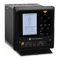
Thytronic XMR-A 4l+1A Manual (385 pages)
Brand:
Thytronic
| Category:
Protection Device
| Size: 22 MB
Table of Contents
Table of Contents
3
1 Introduction
7
Conformity
7
Copyright
7
Insulation Tests
7
Safety Recommendations
7
Scope and Liability
7
Service Support
7
Warranty
7
Environment
9
Glossary/Definitions
9
Graphical Conventions
9
Product Identification
9
Symbols
11
2 General
13
Photo
13
Preface
13
Main Features
14
Cyber Security
15
Auditing
15
Configuration Management
15
Initial System Configuration
15
User Access Procedure
16
XMR Cybersecurity Basic Scheme
16
General
17
EMC Tests for Interference Immunity)
17
Voltage Dip and Interruption
17
Certifications
18
Climatic Tests
18
Emission
18
Mechanical Tests
18
Safety
18
3 Technical Data
17
Measuring Relays and Protection Equipment
17
Mechanical Data
17
Insulation Test
17
Input Circuits
19
Auxiliary Power Supply Uaux
19
Phase Current Inputs with Inductive Cts
19
Phase Voltage Inputs with Inductive Vts
19
Residual Current Input
19
Block Output (Logic Selectivity)
20
Relays
20
Communication Interfaces
20
Local Port
20
Network Ports
20
Protocol
20
Rated Values and General Settings
20
Binary Inputs
21
Input Sequence
21
Output Relays
21
Polarity
21
Rated Values (All Versions)
21
Rated Values for Versions with Inductive CT and VT Inputs
21
Rated Values for Versions with Thysensor Inputs
21
Line
22
Starting Control Set
22
MMI (man Machine Interface)
20
Protective Functions
22
Base Current - IB
22
Overeflux- 24
22
Underimpedance - 21
22
Thermometric Probes - 26
23
Undervoltage - 27
23
100% Stator Earth Fault with 3Rd Harmonic (27H - 59H)
24
Directional Active Overpower 32P
24
Positive Sequence Undervoltage - 27V1
24
Directional Active Underpower 37P
25
Directional Reactive Overpower 32Q
25
Undercurrent - 37
25
Directional Reactive Underpower 37Q
26
Loss of Field - 40
26
Negative Sequence Overcurrent for Line/Transformer Protection- 46LT
26
Negative Sequence Overcurrent for Generator Protection - 46G
27
Negative Sequence Overcurrent for Motor Protection - 46M
28
Negative Sequence / Positive Sequence Current Ratio - I
29
Phase Rotation Direction Check - 47
29
Thermal Image for Line/Transformer Protection - 49LT
29
Thermal Image for Motor/Generator Protection - 49MG
29
Inadvertent Energization - 50/27
30
Phase Overcurrent - 50/51 Side H
30
Phase Overcurrent - 50/51 Side L
31
Locked Rotor - 51LR(48)/14
32
Residual Overcurrent - 50N/51N or High Impedance Restricted Earth Fault - 87NHIZ
33
Voltage-Controlled / Restraint Overcurrent - 51V
33
Calculated Residual Overcurrent - 50N(Comp)/51N(Comp)
35
Minimum Power Factor - 55
36
Overvoltage - 59
36
Residual Overvoltage - 59N
37
Directional Phase Overcurrent - 67
38
High Impedance Restricted Earth Fault - 64REF
38
Maximum Number of Startings (Restart Inhibition) - 66
38
Negative Sequence Overvoltage - 59V2
38
Rotor Earth Fault (64F)
38
Directional Earth Fault Overcurrent- 67N
41
Out of Step - 78
44
Overfrequency - 81O
44
Underfrequency - 81U
44
Differential - 87G-87M-87T
45
Frequency Rate of Change (81R)
45
Breaker Failure - BF (Side L and Side H)
46
Lock-Out - 86
46
Vector Jump
46
Control and Monitoring
47
Synchrocheck - 25
47
Circuit Breaker Supervision
48
CT Supervision - 74CT
48
Demand Measures
48
Internal Selective Block - BLOCK4
48
Oscillography (DFR)
48
Selective Block - BLOCK2
48
VT Supervision - 74VT
48
Arc Flash
49
PLC (Programmable Logic Controller)
49
Accuracy
50
Metering
50
4 Function Characteristics
51
Hardware
51
Power Supply Board
51
CPU Module
51
Input Board
52
MMI (Display, Keyboard and LED)
52
Firmware
53
Base Software
53
Real-Time Operating System
53
Task
53
Drivers
54
Application Software
54
Data Base
54
Self Test (Application)
54
Development Tool (Builder)
54
I/0 Description
55
Metering Inputs
55
CT-VT Input Version
55
Direct
56
Calculated
57
Phase
57
Demand
58
Sequence
58
Energy
59
Power
59
Conventions
60
Cyclic Phase Sequence Order
60
Phase Rotation Direction
60
Use of Measured Signals
63
Binary Inputs
64
Fault Trigger
65
Reset Leds
65
Set Profile
65
Block2 IE
66
Block2 Iph
66
Block2 Iph/Ie
66
Reset Counters
67
TCS1 and TCS2
67
Trip Circuit Supervision
67
Trip Protext
67
Close CB
68
Mcb Vt Open
68
Open CB
68
Preset Dtheta
68
Motor Restart
69
Reset Demand Measures
69
Reset Energy
69
Speed Control
69
Output Relays
70
LED Indicators
71
Communication Interfaces
75
Several Protocol Are Implemented
75
Protective Elements
76
Rated Values
76
Case B
78
Operation and Settings
81
Underimpedance - 21
81
Breaker Failure (BF)
83
Logical Block (Block1)
83
Selective Block (Block2)
83
VT Monitoring (74VT)
83
Overflux - 24
87
Thermal Protection with RTD Thermometric Probes - 26
94
Undervoltage - 27
96
Positive Sequence Undervoltage - 27V1
100
100% Stator Earth-Fault with 3Rd Harmonic: Residual Under-Overvoltage (27H-59H)
102
Directional Active Overpower - 32P
106
Directional Reactive Overpower - 32Q
109
Undercurrent - 37
112
Directional Active Underpower - 37P
114
Directional Reactive Underpower - 37Q
117
Loss of Field - 40
120
Setting for GENERATOR Mode
121
Operating Logic
122
Setting for MOTOR Mode
122
Negative Sequence Overcurrent for Line or Transformer Protection - 46LT
126
Cold Load Pickup
127
Second Harmonic Restraint
127
Use of Binary Inputs
128
Use of Committed Pilot Wire Output BLOUT1
128
Use of Output Relay
128
Negative Sequence Overcurrent for Generator Protection - 46G
133
Negative Sequence Overcurrent for Motor Protection - 46M
138
Phase Rotation Direction Check - 47
145
Thermal Image - 49LT for Line or Transformer Protection (Side H and Side L)
146
Thermal Image - 49MG for Motor or Generator Protection
157
Inadvertent Energization - 50/27
168
Setting Notes ((50+27)
171
Negative Sequence Current / Positive Sequence Current Ratio - I2/I1
172
Phase Overcurrent - 50/51 Side H and Side L
175
Residual Overcurrent - 50N.1/51N.1, 50N.2/51N.2 or High Impedance Restricted Earth Fault - 87NHIZ.1, 87NHIZ.2 Side 1,2
185
Locked Rotor- 50S/51LR(48)/14
196
Voltage Controlled/Restraint Overcurrent - 51V
202
Residual Overcurrent - 50N(Comp)/51N(Comp) Side H or Side L
209
Minimum Power Factor - 55
219
Overvoltage - 59
223
Residual Overvoltage - 59N
227
Negative Sequence Overvoltage - 59V2
231
Rotor Earth Fault - 64F
233
Low Impedance Restricted Ground Fault- 64REF
238
Maximum Number of Starts - 66
241
Phase Directional Overcurrent - 67
243
Ground Directional Overcurrent - 67N
259
Ground Directional Overcurrent with Calculated Residual Current - 67N(Comp)
282
Out of Step - 78
294
Overfrequency - 81O
303
Underfrequency - 81U
305
Frequency Rate Change - 81R
308
Vector Jump - Dphi
326
Breaker Failure - BF
328
Control and Monitoring
334
Synchrocheck - 25
334
Remote Tripping
342
Second Harmonic Restraint - 2Ndh-REST
343
CT Supervision - 74CT
344
VT Supervision - 74VT
345
Trip Circuit Supervision - 74TCS
347
Virtual I/O
350
Circuit Breaker Supervision (Side H and Side L)
353
Oscillography
355
Arc Flash Protection
356
5 Measures, Logic States and Counters
357
Measures
357
Delayed Inputs
358
Protections
358
Self Test
358
Event Recording - SER
359
Fault Recording - SFR
359
Oscillography - DFR
359
Pilot Wire Diagnostic
359
Selective Block - BLOCK2
359
6 Installation
361
Mounting
361
Packaging
361
Electrical Connections
363
Final Operations
371
Led Commissioning
371
RATED in and Ien SETTINGS
371
7 Programming and Settings
372
SW Thyvisor
372
Thyvisor Use
372
MMI (man Machine Interface)
373
Reading Variables (READ)
373
Setting Modifying (SET)
374
Test
375
Communication
375
Circuit Breaker Commands
375
Enable / Block Changes Via Keyboard - Password
376
Maintenance
377
Packaging
377
8 Appendix
378
Repair
377
Appendix A1 - Input-Output Scheme
378
Appendix A2 - Protection Functions
379
Appendix A3 - Application Schemes
380
APPENDIX B - EC Conformity Declaration
384
Advertisement
Advertisement
Related Products
Thytronic XMR-D 4l+4V
Thytronic XMR-A 4l+1V
Thytronic XMR-V 4V
Thytronic NG10
Thytronic XMR-D
Thytronic XMR-P 4l+4V
Thytronic XMR-T
Thytronic XMR-T 8l+1V
Thytronic XMR-T PRO 11l+1V
Thytronic Categories
Relays
Security Sensors
Protection Device
Power distribution unit
Industrial Electrical
More Thytronic Manuals
Login
Sign In
OR
Sign in with Facebook
Sign in with Google
Upload manual
Upload from disk
Upload from URL