Table of Contents
Advertisement
Advertisement
Table of Contents

Subscribe to Our Youtube Channel
Related Manuals for Thytronic XMR-T


Summary of Contents for Thytronic XMR-T
- Page 1 XMR-T GROUP “8I+1V+[PRO(11I+1V)” MANUAL XMR-T EQUIPMENT MANUAL Ed. 2.9 - 02/2021...
- Page 2 INTENTIONALLY BLANK PAGE XMR-T EQUIPMENT MANUAL Ed. 2.9 - 02/2021...
-
Page 3: Table Of Contents
Residual overvoltage - 59N ..................................26 High impedance restricted earth fault - 64REF 1, 2 ..........................27 Overfrequency - 81O .....................................27 Underfrequency - 81U ....................................27 Differential - 87G-87M-87T ..................................28 3.8 CONTROL AND MONITORING ..................................28 XMR-T EQUIPMENT MANUAL Ed. 2.9 - 02/2021... - Page 4 Virtual I/O ........................................163 Circuit breaker supervision ..................................166 Oscillography ......................................168 Arc Flash Protection ....................................169 — 5 MEASURES, LOGIC STATES AND COUNTERS Measures ........................................170 Protections ........................................171 Delayed inputs ......................................171 Self test .........................................171 XMR-T EQUIPMENT MANUAL Ed. 2.9 - 02/2021...
- Page 5 — 8 APPENDIX 8.1 APPENDIX A1 - INPUT-OUTPUT SCHEME..............................191 8.2 APPENDIX A2 - PROTECTION FUNCTIONS ..............................192 8.3 APPENDIX A3 - APPLICATION SCHEMES ..............................193 8.4 APPENDIX B - EC Conformity Declaration ..............................198 XMR-T EQUIPMENT MANUAL Ed. 2.9 - 02/2021...
-
Page 6: Introduction
This document contains the description of all the protection functions present in the versions XMR-A, XMR-V, XMR-P, XMR-D and XMR-T; for the functions actually present in the single ones versions refer to the table on the following page. - Page 7 Multiple Profiles (A, B, C, D) Work in Progress Threshold key n (1,2) - m (1,2,3,4,5,6) - p (1,2,3) - q (1,2,3,4) - w (1,2,3,4,5) Standard Optional with requested SW Package Optional with requested HW Expansion XMR-T EQUIPMENT MANUAL INTRODUCTION Ed. 2.9 - 02/2021...
-
Page 8: Product Identification
Note 1 The rating data can be found on labels on the back and on the front (accessible after removing the left frame) Note 2 The rating data can be found on labels on the front plate (accessible after removing the right frame) XMR-T EQUIPMENT MANUAL INTRODUCTION... - Page 9 The declared values for the overshoot time are applicable with the lower setting value of the operation time. XMR-T EQUIPMENT MANUAL INTRODUCTION Ed. 2.9 - 02/2021...
- Page 10 OR and NOR logic gates ≥1 ≥1 EXOR logic gate Flip Flop set-dominant INPUT ON delay timer with reset ( delay) OUTPUT RESET RESET INPUT ON delay timer without reset ( delay) OUTPUT Symbols.ai XMR-T EQUIPMENT MANUAL INTRODUCTION Ed. 2.9 - 02/2021...
- Page 11 RESET INPUT Minimum pulse width operation for output relays ( OUTPUT INPUT Latched operating mode for output relays and LEDs Latched OUTPUT INPUT Pulse operating mode for output relays OUTPUT Symbols1 .ai XMR-T EQUIPMENT MANUAL INTRODUCTION Ed. 2.9 - 02/2021...
-
Page 12: General
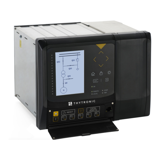
The methods of calibration, programming and reading of the measurements and recordings can be implemented through Personal Computer with Software support ( ThyVisor) or via bus RS485 or Ether- net communication; all the above operations are possible using the keyboard frontal view (MMI). Photo — XMR-T EQUIPMENT MANUAL GENERAL Ed. 2.9 - 02/2021... -
Page 13: Main Features
◊ Module 8 PT100 (XMPT) ◊ Module 32 Digital Inputs (XMID32) ◊ Module 16 Digital Outputs (XMR16) ◊ Module 6 Analogue Outputs 4÷20mA (XMCI) ◊ Rotor-Ground Protection Module (XMR-P and XMR-D ONLY) XMR-T EQUIPMENT MANUAL GENERAL Ed. 2.9 - 02/2021... -
Page 14: Cyber Security
CID sending, etc. are routed via the “SSH” protocol, in encrypted mode. Data exchange protocols with the SCADA, e.g. IEC61850 / DNP3 / MODBUSTCP are unencrypted, if IEC62351 specification is not expressly requested. The synchronization protocols NTP, PTP are normally unencrypted. XMR-T EQUIPMENT MANUAL GENERAL Ed. 2.9 - 02/2021... - Page 15 The RADIUS authentication as a reference to a remote server and uses a shared secret between card and server for validation of access requests. The configurator provides the possibility to define all parameters necessary for this authentication mode. XMR-T EQUIPMENT MANUAL GENERAL Ed. 2.9 - 02/2021...
-
Page 16: Technical Data
— Mounting: • Flush • Rack External dimensions Basic version (XMR-A, XMR-V, XMR-P) 171 x 178 x 246 (H/W/D) External dimensions Basic version (XMR-D, XMR-T) 243 x 178 x 246 (H/W/D) Terminals screw connection Mass (XMR-A, XMR-V, XMR-P) 4.5 kg Mass (XMR-D, XMR-T) 5.5 kg... -
Page 17: Emission
IEC 60255-27 Pollution degree Reference voltage 250 V Overvoltage category — Certifications Product standards EN 50263 CE Conformity • EMC Directive 2014/30/EC • Low Voltage Directive 2014/35/EC Type tests IEC 60255-1 XMR-T EQUIPMENT MANUAL TECHNICAL DATA Ed. 2.9 - 02/2021... -
Page 18: Input Circuits
Make (SPST-NO, type A) Rated current Short duration current (0,5 s) 30 A Rated voltage/max switching voltage 250 V~/400 V~ Make 1000 W/VA Minimum switching load 300 mW (5 V/ 5 mA) XMR-T EQUIPMENT MANUAL TECHNICAL DATA Ed. 2.9 - 02/2021... -
Page 19: Block Output (Logic Selectivity)
Residual primary nominal voltage (phase-to-phase) ∙√3 (U ) 50 V...500 kV 50...499 V (step 1 V) 500...4990 V (step 10 V) 5000...49900 V (step 100 V) 50000...500000 V (step 1000 V) XMR-T EQUIPMENT MANUAL TECHNICAL DATA Ed. 2.9 - 02/2021... -
Page 20: Binary Inputs
0.10...9.99 s (step 0.01 s) 10.0...100.0 s (step 0.1 s) Pickup time ≤ 0.04 s Dropout ratio 0.95...0.98 Dropout time ≤ 0.05 s Overshoot time 0.04 s Pickup accuracy ± 0.5% on voltage measures XMR-T EQUIPMENT MANUAL TECHNICAL DATA Ed. 2.9 - 02/2021... -
Page 21: Thermometric Probes - 26
Note 7 The mathematical formula for INVERSE curve is: t= (0.75 ∙ operating time (in seconds) U/U< < : operating time setting (referred to = 0.25 ) input voltage U< : threshold setting XMR-T EQUIPMENT MANUAL TECHNICAL DATA Ed. 2.9 - 02/2021... -
Page 22: Negative Sequence / Positive Sequence Current Ratio - I (H, L, T)
Asymptotic reference value: 1.1 I> Minimum operate time: 0.1 s Equation is valid for 1.1 ≤ I/I> ≤ 20 With I> pickup ≥ 2.5 I , the upper limit is 50 I XMR-T EQUIPMENT MANUAL TECHNICAL DATA Ed. 2.9 - 02/2021... -
Page 23: Thermal Image For Line/Transformer Protection - 49 (H, L, T)
L, T 0.100...0.999 I (step 0.001 I nH, L, T 1.00...20.00 I (step 0.01 I nH, L, T Operating time (t > 0.02...60.0 s (H, L, T) 0.02...9.99 s (step 0.01 s) XMR-T EQUIPMENT MANUAL TECHNICAL DATA Ed. 2.9 - 02/2021... -
Page 24: Residual Overcurrent - 50N/51N Or High Impedance Restricted Earth Fault - 87Nhiz
10.0...100.0 s (step 0.1 s) Reset time delay (t > 0.00...100.0 s 0.00...9.99 s (step 0.01 s) 10.0...100.0 s (step 0.1 s) Definite time First threshold definite time (I > 0.002...10.00 I XMR-T EQUIPMENT MANUAL TECHNICAL DATA Ed. 2.9 - 02/2021... - Page 25 Asymptotic reference value: 1.1 I > Minimum operate time: 0.1 s Equation is valid for 1.1 ≤ I > ≤ 20, with I > pickup ≥ 0.5 I , the upper limit is 10 I XMR-T EQUIPMENT MANUAL TECHNICAL DATA Ed. 2.9 - 02/2021...
-
Page 26: Overvoltage - 59
= 1.5) residual input voltage (direct or calculated) > : threshold setting > Asymptotic reference value: 1.1 Minimum operate time: 0.1 s > Equation is valid for 1.1 ≤ ≤ 4 XMR-T EQUIPMENT MANUAL TECHNICAL DATA Ed. 2.9 - 02/2021... -
Page 27: High Impedance Restricted Earth Fault - 64Ref 1, 2
+ 0.2 Hz trip: setting value - 0.2 Hz Pickup accuracy ±5 mHz with 0.02 U , ± 2 mHz with 1U Operate time accuracy 5% ± 10 ms XMR-T EQUIPMENT MANUAL TECHNICAL DATA Ed. 2.9 - 02/2021... -
Page 28: Differential - 87G-87M-87T
(H) Residual current threshold (I >) 0.01...2.00 I (step 0.01 I EBF (H) n (H) En (H) Time delay(t 0.06...10.00 s (step 0.01 s) BF (H) Pickup time ≤ 0.04 s XMR-T EQUIPMENT MANUAL TECHNICAL DATA Ed. 2.9 - 02/2021... -
Page 29: Circuit Breaker Supervision (H, L, T)
START, TRIP, L1...L16 Block outputs BLK2OUT-Iph, BLK2OUT-IE,... Note 1 For the DFR function a licence is required; call Thytronic for purchasing. Nota 3 For the PLC function a licence is required; call Thytronic for purchasing XMR-T EQUIPMENT MANUAL TECHNICAL DATA... -
Page 30: Arc Flash
= 0.01 U or U = 0.15 U 0.3% Pickup and operate time 1.5 x setting for fist element 5% ± 10 ms 2.5 x setting for other elements 5% ± 10 ms XMR-T EQUIPMENT MANUAL TECHNICAL DATA Ed. 2.9 - 02/2021... -
Page 31: Function Characteristics
The circuit provides stabilized voltages required for the analogue measurement,for relays and for supplying the digital circuits. — CPU module This circuit board contains all the circuits necessary for performing the analogue and digital proces- sing of the signals. XMR-T EQUIPMENT MANUAL FUNCTION CHARACTERISTICS Ed. 2.9 - 02/2021... -
Page 32: Input Board
• Membrane keyboard with 10 keys • Twenty one signaling LED • Ethernet port for local interface Note 1 The phase and residual nominal currents must be adjusted by means dip-switch. XMR-T EQUIPMENT MANUAL FUNCTION CHARACTERISTICS Ed. 2.9 - 02/2021... -
Page 33: Firmware
By means of Discrete Fourier Transform calculation, based on 64 samples/period, information is de- duced in relation to the amplitude and phase of all the current measurements; these are constantly updated and at the disposal of all the protection and control application algorithms. XMR-T EQUIPMENT MANUAL FUNCTION CHARACTERISTICS Ed. 2.9 - 02/2021... -
Page 34: Drivers
Xml files used for communication. The automatic code generation criteria ensures the quality of the result in terms of the reusability, verifiability and maintainability of the software life cycle. XMR-T EQUIPMENT MANUAL FUNCTION CHARACTERISTICS Ed. 2.9 - 02/2021... -
Page 35: I/0 Description
From the sampled quantities, several measures are computed for protection, monitoring and mete- ring purposes. • Direct • Calculated • Phase • Sequence • Power • Harmonic • Demand • Energy XMR-T EQUIPMENT MANUAL FUNCTION CHARACTERISTICS Ed. 2.9 - 02/2021... - Page 36 UL1. a i • Residual current I ACQUISITION ≈ IE . ai • Residual voltage U (traditional VT inputs only) ACQUISITION DFT (fundamental) ≈ DFT (3rd harmonic) UE . a i XMR-T EQUIPMENT MANUAL FUNCTION CHARACTERISTICS Ed. 2.9 - 02/2021...
- Page 37 ThySensor or when the input is employed for the synchrocheck function, the residual voltage is only available as a calculated measure U Note 2 The adjustment and display range of displacements are 0°... 359° XMR-T EQUIPMENT MANUAL FUNCTION CHARACTERISTICS Ed. 2.9 - 02/2021...
- Page 38 L x MA X L x n L 3 MA X R OL ±P ∑ MA X ±P ±P MA X ±P R OL ±Q ±Q ∑ ±Q ±Q MA X MA X Max-Demand.ai XMR-T EQUIPMENT MANUAL FUNCTION CHARACTERISTICS Ed. 2.9 - 02/2021...
- Page 39 = ∫(P dt) (Wh) +, E + = ∫(+Q dt) - = ∫(-Q dt) = ∫(Q dt) (varh) E. a i Use of over-described measures is shown in the following tables. XMR-T EQUIPMENT MANUAL FUNCTION CHARACTERISTICS Ed. 2.9 - 02/2021...
-
Page 40: Conventions
(allways counted counterclockwise) Alpha1=120° Alpha1=60° Displacement angle of I respect U phase-to-phase voltage (allways counted counterclockwise) Displacements convenzioni-sfasamenti.ai Note 1 The adjustment and display range of displacements are 0°... 359° XMR-T EQUIPMENT MANUAL FUNCTION CHARACTERISTICS Ed. 2.9 - 02/2021... - Page 41 SYSTEM +cos ϕ, +cos ϕ , +cos ϕ , +cos ϕ -cos ϕ, -cos ϕ , -cos ϕ , -cos ϕ -Q, -Q , -Q , -Q III° IV° convenzioni2.ai XMR-T EQUIPMENT MANUAL FUNCTION CHARACTERISTICS Ed. 2.9 - 02/2021...
- Page 42 , +P -cos ϕ, -cos ϕ , -cos ϕ , -cos ϕ +cos ϕ, +cos ϕ , +cos ϕ , +cos ϕ -Q, -Q , -Q , -Q III° IV° convenzioni4.ai XMR-T EQUIPMENT MANUAL FUNCTION CHARACTERISTICS Ed. 2.9 - 02/2021...
-
Page 43: Use Of Measured Signals
Record ... XMR-T EQUIPMENT MANUAL FUNCTION CHARACTERISTICS Ed. 2.9 - 02/2021... -
Page 44: Binary Inputs
In the diagram, INTERNAL STATE represents the logical state of the binary input used in the following processing. Each binary input may be matched to one of the following default functions (eg. Board 1 inputs for XMR-x versions). XMR-T EQUIPMENT MANUAL FUNCTION CHARACTERISTICS Ed. 2.9 - 02/2021... - Page 45 Note 1 To enable the profile switching the “Input-selected” parameter must be set inside the “Profile selection” submenu. If multiple setting groups are not required, Group A is the default selection XMR-T EQUIPMENT MANUAL FUNCTION CHARACTERISTICS Ed. 2.9 - 02/2021...
- Page 46 Note 4 The activation of one binary input produces indiscriminately a block of all protective elements programmed for being blocked from Block1 XMR-T EQUIPMENT MANUAL FUNCTION CHARACTERISTICS Ed. 2.9 - 02/2021...
- Page 47 The external acquisition of remote commands allows to drive CB remotely. Note 1 The reset of the total counters is practicable by means ThyVisor command with Session Level 1 (available with password) XMR-T EQUIPMENT MANUAL FUNCTION CHARACTERISTICS Ed. 2.9 - 02/2021...
- Page 48 (59N and 67N protections) that may operate inadvertently when an event cause a loss of one or more voltages. XMR-T EQUIPMENT MANUAL FUNCTION CHARACTERISTICS Ed. 2.9 - 02/2021...
-
Page 49: Output Relays
Matching of the output relay to the protective and control functions can be defined so that any collision from other function is avoided. All output relay are unassigned in the default setting. XMR-T EQUIPMENT MANUAL FUNCTION CHARACTERISTICS Ed. 2.9 - 02/2021... -
Page 50: Led Indicators
Note 1 The START and the TRIP LED are user assignable to any function; other than starting and tripping information can be assigned to them too, just the same for L1...L5 Note 2 All features are listed; functions effectively present depend on the version All LEDs are unassigned in the default setting. XMR-T EQUIPMENT MANUAL FUNCTION CHARACTERISTICS Ed. 2.9 - 02/2021... - Page 51 81U Forth element Start LEDs (f<<<<ST-L) 81U Forth element Trip LEDs (f<<<<TR-L) XMR-T EQUIPMENT MANUAL FUNCTION CHARACTERISTICS Ed. 2.9 - 02/2021...
- Page 52 Remote Trip (RemTrip-L) Not received pulses at BLIN signalling LEDs (PulseBLIN-L) XMR-T EQUIPMENT MANUAL FUNCTION CHARACTERISTICS Ed. 2.9 - 02/2021...
-
Page 53: Communication Interfaces
Note 2 Under normal conditions, the primary port is active, while the secondary port is activated automatically in the event of failure of the primary port or with hw-sw switching command XMR-T EQUIPMENT MANUAL FUNCTION CHARACTERISTICS Ed. 2.9 - 02/2021... -
Page 54: Protective Elements
Nota 2 Per rendere attiva la modifica della regolazione, dopo il comando “Fine tarature“ è necessario RIAVVIARE IL DISPOSITIVO Nota 3 Per rendere attiva la modifica della regolazione, dopo il comando “Fine tarature“ è necessario RIAVVIARE IL DISPOSITIVO XMR-T EQUIPMENT MANUAL FUNCTION CHARACTERISTICS... - Page 55 = 6 kV Insulated or impedance-ground neutral XMR-x 6000 = 60 · 100 / 3 Grid rated voltage U = 6 kV 6000 = 60 · VT ratio: 100 3 Es2-UEn.ai XMR-T EQUIPMENT MANUAL FUNCTION CHARACTERISTICS Ed. 2.9 - 02/2021...
- Page 56 Ratio of line VTs K = 60 Es4-UEn.ai For the example 2 U = 100 V. U is estimated automatically by means of the formula: ∙ √3 = 100 ∙ √3 = 173 V XMR-T EQUIPMENT MANUAL FUNCTION CHARACTERISTICS Ed. 2.9 - 02/2021...
- Page 57 Grid rated voltage U = 6.9 kV 10000 VTs ratio: = 100 Relay rated voltage U = 69 V Es1-Ung.ai The Unp setting must be adjusted to: Unp = Ung = 6.9 kV XMR-T EQUIPMENT MANUAL FUNCTION CHARACTERISTICS Ed. 2.9 - 02/2021...
- Page 58 Measures may be displayed according the following operating modes: - With RELATIVE setting all measures are related to the nominal value, - With PRIMARY setting all measures are related to the primary value. XMR-T EQUIPMENT MANUAL FUNCTION CHARACTERISTICS Ed. 2.9 - 02/2021...
-
Page 59: Overflux - 24
Minimum ratio(U/f ) : 1.1 (U/f )> Minimum operate time: 0.1 s Range where the equation is valid: 1.1 ≤ (U/f )> ≤ 5, the upper limit for measuring is 10 U XMR-T EQUIPMENT MANUAL FUNCTION CHARACTERISTICS Ed. 2.9 - 02/2021... - Page 60 U/f> Block1 Block1 & Block1 Logic INx t INx t n.c. Block1 input (ON≡Block) INx t INx t Block1 n.o. Binary input INx Overfluxing protection (24) - Alarm element logic diagram Fun-F24_S1.ai XMR-T EQUIPMENT MANUAL FUNCTION CHARACTERISTICS Ed. 2.9 - 02/2021...
- Page 61 Set \ Board 1(2) inputs \ Binary input IN1-1... (IN1-x) menus. Note 1 The exhaustive treatment of the logical block (Block 1) function may be found in the “Logic Block” paragraph inside CONTROL AND MONITOR- ING section. XMR-T EQUIPMENT MANUAL FUNCTION CHARACTERISTICS Ed. 2.9 - 02/2021...
- Page 62 & U/f>> Block1 Block1 & Block1 Logic INx t INx t n.c. INx t INx t Block1 n.o. Binary input INx (x=1...8-16) Overfluxing protection (24) - Second element logic diagram Fun-F24_S3.ai XMR-T EQUIPMENT MANUAL FUNCTION CHARACTERISTICS Ed. 2.9 - 02/2021...
- Page 63 0.01 (U/f )/(U/f >) Note: match of operating and setting time takes place when (U/f )/(U/f >) = 700 IEC type A inverse time characteristic concerning the first element (24) IEC-type_A-F24.ai XMR-T EQUIPMENT MANUAL FUNCTION CHARACTERISTICS Ed. 2.9 - 02/2021...
- Page 64 0.02 0.01 (U/f )/(U/f >) Note: match of operating and setting time takes place when (U/f )/(U/f >) = 14.5 IEC type B inverse time characteristic concerning the first element (24) XMR-T EQUIPMENT MANUAL FUNCTION CHARACTERISTICS Ed. 2.9 - 02/2021...
- Page 65 0.04 0.03 0.02 0.01 (U/f )/(U/f >) Note: match of operating and setting time takes place when (U/f )/(U/f >) IEC type C inverse time characteristic concerning the first element (24) XMR-T EQUIPMENT MANUAL FUNCTION CHARACTERISTICS Ed. 2.9 - 02/2021...
-
Page 66: Thermal Protection With Rtd Thermometric Probes - 26
0 . 2 5 s 0 . 2 5 s 0 . 2 5 s Pt1...8 update t-refresh-F26.ai Note 1 The 26 menu is available when the MPT module is enabled XMR-T EQUIPMENT MANUAL FUNCTION CHARACTERISTICS Ed. 2.9 - 02/2021... - Page 67 It is recommended to position connections to the probe away from power lines to avoid interference. Note 1 The common settings concerning the Breaker failure protection are adjustable inside the Breaker Failure - BF menu. XMR-T EQUIPMENT MANUAL FUNCTION CHARACTERISTICS...
-
Page 68: Undervoltage - 27
OR), is adjustable inside the Set \ Profile A (or B or C or D)\ Undervoltage-27 \ Common configura- tion menu by means the Utype27 parameter; the allowed setting are Uph-ph (phase-to-phase) or Uph-n (phase-to-neutral). for Uph-ph setting and p.u. E for Uph-n setting. The corresponding unit are p.u. U XMR-T EQUIPMENT MANUAL FUNCTION CHARACTERISTICS Ed. 2.9 - 02/2021... - Page 69 Note 2 The exhaustive treatment of the VT supervision function may be found in the “VT supervision - 74VT” paragraph inside CONTROL AND MONI- TORING section. Note 3 The exhaustive treatment of the logical block (Block 1) function may be found in the “Logic Block” paragraph inside CONTROL AND MONITOR- ING section. XMR-T EQUIPMENT MANUAL FUNCTION CHARACTERISTICS Ed. 2.9 - 02/2021...
- Page 70 INx t INx t Block1 n.c. INx t Block1 input (ON≡Block) INx t Block1 n.o. Binary input INx Logic diagram concerning the second threshold (U<<) of the undervoltage element - 27 Fun-F27_S2.ai XMR-T EQUIPMENT MANUAL FUNCTION CHARACTERISTICS Ed. 2.9 - 02/2021...
- Page 71 0.01 0.25 Note: match of operating and setting time takes place when U/U< = 0.25 Inverse time operating characteristic concerning the first threshold (U<) of the undervoltage element - 27 F_27-Char.ai XMR-T EQUIPMENT MANUAL FUNCTION CHARACTERISTICS Ed. 2.9 - 02/2021...
-
Page 72: Undercurrent - 37 (H, L, T)
The parameter may be adjusted independently for Profile A or B, C, D. Note 1 The description of the logical block (Block 1) function may be found in the “Logic Block” paragraph inside CONTROL AND MONITORING section. XMR-T EQUIPMENT MANUAL FUNCTION CHARACTERISTICS... - Page 73 INx t INx t Block1 n.c. INx t Block1 input (ON≡Block) INx t Block1 n.o. Binary input INx (x=1...8-16) Logic diagram concerning the threshold (I<) of the undercurrent element - 37 Fun-F37_S1.ai XMR-T EQUIPMENT MANUAL FUNCTION CHARACTERISTICS Ed. 2.9 - 02/2021...
-
Page 74: Negative Sequence Overcurrent For Line Or Transformer Protection - 46 (H, L, T)
The first overcurrent element can be programmed with definite or inverse time characteristic by Note 1 When the input value is more than 20 times the set point , the operate time is limited to the value corresponding to 20 times the set point XMR-T EQUIPMENT MANUAL FUNCTION CHARACTERISTICS... - Page 75 Note 2 The common settings concerning the Breaker failure protection are adjustable inside the Breaker Failure - BF menu. Note 3 The exhaustive treatment of the logical block (Block 1) function may be found in the “Logic Block” paragraph inside CONTROL AND MONITOR- ING section XMR-T EQUIPMENT MANUAL FUNCTION CHARACTERISTICS Ed. 2.9 - 02/2021...
- Page 76 Start I2>> I2>>BLK1 BLK1I2>> Block1 & & Start I2>> I2>>BLK2IN BLK2INI>> & & Block2 I2>>BLK2OUT BLK2OUT Start I2>> & General logic diagram of the negative sequence overcurrent elements - 46LT all-F46.ai XMR-T EQUIPMENT MANUAL FUNCTION CHARACTERISTICS Ed. 2.9 - 02/2021...
- Page 77 CB OPEN CB CLOSED CB OPEN 0.1 s 2CLP> Output t 2CLP> HIGH THRESHOLD/ LOW THRESHOLD/ HIGH THRESHOLD/ BLOCK UNBLOCK BLOCK Negative sequence overcurrent (46LT) - first threshold logic diagram (I2>) 46LTS1.ai XMR-T EQUIPMENT MANUAL FUNCTION CHARACTERISTICS Ed. 2.9 - 02/2021...
- Page 78 >> Block2 OUT F-IE ≥1 BLOUT1 >>> Block2 OUT Pilot wire output ST-IE BLK2 Block2 output Negative sequence overcurrent (46LT) - Logic diagram of the blocking signals concerning the first element (I2>) XMR-T EQUIPMENT MANUAL FUNCTION CHARACTERISTICS Ed. 2.9 - 02/2021...
- Page 79 CB OPEN CB CLOSED CB OPEN 0.1 s 2CLP>> Output t 2CLP>> HIGH THRESHOLD/ LOW THRESHOLD/ HIGH THRESHOLD/ BLOCK UNBLOCK BLOCK Negative sequence overcurrent (46LT) - second threshold logic diagram (I2>>) 46LTS2.ai XMR-T EQUIPMENT MANUAL FUNCTION CHARACTERISTICS Ed. 2.9 - 02/2021...
- Page 80 >> Block2 OUT F-IE ≥1 BLOUT1 >>> Block2 OUT Pilot wire output ST-IE BLK2 Block2 output Negative sequence overcurrent (46LT) - Logic diagram of the blocking signals concerning the second element (I2>>) XMR-T EQUIPMENT MANUAL FUNCTION CHARACTERISTICS Ed. 2.9 - 02/2021...
-
Page 81: Thermal Image - 49Lt For Line Or Transformer Protection (H, L, T)
• Range where the equation is valid: 1.1I ≤ I ≤ 10I • If 10I ≤ I ≤ 20I , the operating time is fixed to a value corresponding to the 10I The upper limit is 20I XMR-T EQUIPMENT MANUAL FUNCTION CHARACTERISTICS Ed. 2.9 - 02/2021... - Page 82 • Set \ Profile A (or B or C or D)\ Breaker failure Note 4 The common settings concerning the Breaker failure protection are adjustable inside the Breaker Failure - BF menu. XMR-T EQUIPMENT MANUAL FUNCTION CHARACTERISTICS Ed. 2.9 - 02/2021...
- Page 83 Transmission and reception for the same element is not allowed, so any stall situation due to wrong setting is avoided. The internal selective block can work together with an external selective block from other protective relays (Block2). XMR-T EQUIPMENT MANUAL FUNCTION CHARACTERISTICS Ed. 2.9 - 02/2021...
- Page 84 CB CLOSED CB OPEN 0.1 s DthCLP Output t DthCLP HIGH THRESHOLD/ LOW THRESHOLD/ HIGH THRESHOLD/ BLOCK UNBLOCK BLOCK Thermal image (49LT) - Logic diagram of the first alarm threshold Fun_49_AL1.ai XMR-T EQUIPMENT MANUAL FUNCTION CHARACTERISTICS Ed. 2.9 - 02/2021...
- Page 85 >>>Block4 I/O >> Block4 I/O ST-IE BLK4 >>>>Block4 I/O >>> Block4 I/O >>>> Block4 I/O Block4 Thermal image (49LT) - Logic diagram of the blocking signals concerning the first alarm element XMR-T EQUIPMENT MANUAL FUNCTION CHARACTERISTICS Ed. 2.9 - 02/2021...
- Page 86 CB CLOSED CB OPEN 0.1 s DthCLP Output t DthCLP HIGH THRESHOLD/ LOW THRESHOLD/ HIGH THRESHOLD/ BLOCK UNBLOCK BLOCK Thermal image (49LT) - Logic diagram of the second alarm threshold Fun_49_AL2.ai XMR-T EQUIPMENT MANUAL FUNCTION CHARACTERISTICS Ed. 2.9 - 02/2021...
- Page 87 >>>Block4 I/O >> Block4 I/O ST-IE BLK4 >>>>Block4 I/O >>> Block4 I/O >>>> Block4 I/O Block4 Thermal image (49LT) - Logic diagram of the blocking signals concerning the second alarm element XMR-T EQUIPMENT MANUAL FUNCTION CHARACTERISTICS Ed. 2.9 - 02/2021...
- Page 88 CB OPEN CB CLOSED CB OPEN 0.1 s DthCLP Output t DthCLP HIGH THRESHOLD/ LOW THRESHOLD/ HIGH THRESHOLD/ BLOCK UNBLOCK BLOCK Thermal image (49LT) - Logic diagram of the trip threshold Fun_49_Dth.ai XMR-T EQUIPMENT MANUAL FUNCTION CHARACTERISTICS Ed. 2.9 - 02/2021...
- Page 89 ≥1 >>>Block4 I/O >> Block4 I/O ST-IE BLK4 >>>>Block4 I/O >>> Block4 I/O >>>> Block4 I/O Block4 Thermal image (49LT) - Logic diagram of the blocking signals concerning the trip element XMR-T EQUIPMENT MANUAL FUNCTION CHARACTERISTICS Ed. 2.9 - 02/2021...
- Page 90 [s] 10000 1000 0 .0 0 .6 0 .8 1 .0 0.01 7 8 9 10 Operating characteristic concerning the thermal image element (49LT) - T=1 min F_49-1min-Char.ai XMR-T EQUIPMENT MANUAL FUNCTION CHARACTERISTICS Ed. 2.9 - 02/2021...
- Page 91 [s] 100000 10000 1000 0 .0 0 .6 0 .8 1 .0 7 8 9 10 Operating characteristic concerning the thermal image element (49LT) - T = 200 min F_49-200min-Char.ai XMR-T EQUIPMENT MANUAL FUNCTION CHARACTERISTICS Ed. 2.9 - 02/2021...
-
Page 92: Negative Sequence Current / Positive Sequence Current Ratio - I2/I1 (H, L, T)
After expiry of the associated operate time (t >) a trip command is issued; if instead the I2/I1 ratio drops below the threshold, the element is restored. XMR-T EQUIPMENT MANUAL FUNCTION CHARACTERISTICS Ed. 2.9 - 02/2021... - Page 93 Note 2 The setting may be found in the “CT supervision ” paragraph inside CONTROL AND MONITORING section Note 3 The description of the logical block (Block 1) function may be found in the “Logic Block” paragraph inside CONTROL AND MONITORING section XMR-T EQUIPMENT MANUAL FUNCTION CHARACTERISTICS...
- Page 94 CB OPEN CB CLOSED CB OPEN 0.1 s 21CLP> Output t 21CLP> HIGH THRESHOLD/ LOW THRESHOLD/ HIGH THRESHOLD/ BLOCK UNBLOCK BLOCK Negative sequence-positive sequence ratio element (I2/I1) - Logic diagram I2-I1S1.ai XMR-T EQUIPMENT MANUAL FUNCTION CHARACTERISTICS Ed. 2.9 - 02/2021...
-
Page 95: Phase Overcurrent - 50/51 (H, L, T)
Note 1 When the input value is more than 20 times the set point , the operate time is limited to the value corresponding to 20 times the set point XMR-T EQUIPMENT MANUAL FUNCTION CHARACTERISTICS Ed. 2.9 - 02/2021... - Page 96 Note 1 The common settings concerning the Breaker failure protection are adjustable inside the Breaker Failure - BF menu. Note 2 The exhaustive treatment of the logical block (Block 1) function may be found in the “Logic Block” paragraph inside CONTROL AND MONITOR- ING section XMR-T EQUIPMENT MANUAL FUNCTION CHARACTERISTICS Ed. 2.9 - 02/2021...
- Page 97 & Block1 I(H)>>>BLK2IN Start I(H)>>> BLK2INI(H)>>> & & Block2 I(H)>>>BLK2OUT BLK2OUT I(H)>>>BLK4 & Start I(H)>>> BLK4OUT & Start I(H)>>> General logic diagram of the overcurrent elements - 50/51 side H all-F50-51.ai XMR-T EQUIPMENT MANUAL FUNCTION CHARACTERISTICS Ed. 2.9 - 02/2021...
- Page 98 Note 1 The exhaustive treatment of the selective block (Block 2) function may be found in the “Selective Block” paragraph inside CONTROL AND MONITORING section Nota 2 The exhaustive treatment of the internal selective block (Block 4) function may be found in the “Internal selective block” paragraph inside CONTROL AND MONITORING section. XMR-T EQUIPMENT MANUAL FUNCTION CHARACTERISTICS Ed. 2.9 - 02/2021...
- Page 99 CB CLOSED CB OPEN 0.1 s CLP> Output t CLP> HIGH THRESHOLD/ LOW THRESHOLD/ HIGH THRESHOLD/ BLOCK UNBLOCK BLOCK Phase overcurrent (50/51) side H - First element logic diagram (I>) Fun_50-51S1.ai XMR-T EQUIPMENT MANUAL FUNCTION CHARACTERISTICS Ed. 2.9 - 02/2021...
- Page 100 ST-IE BLK4 (see BLK2OUT chapter) (see BLK4 chapter) Block4 Phase overcurrent (50/51) side H - Logic diagram of the blocking signals concerning the first element (I(H)>) XMR-T EQUIPMENT MANUAL FUNCTION CHARACTERISTICS Ed. 2.9 - 02/2021...
- Page 101 CB CLOSED CB OPEN 0.1 s CLP>> Output t > > HIGH THRESHOLD/ LOW THRESHOLD/ HIGH THRESHOLD/ BLOCK UNBLOCK BLOCK Phase overcurrent (50/51) side H - Second element logic diagram (I(H)>>) Fun_50-51S2.ai XMR-T EQUIPMENT MANUAL FUNCTION CHARACTERISTICS Ed. 2.9 - 02/2021...
- Page 102 ST-IE BLK4 (see BLK2OUT chapter) (see BLK4 chapter) Block4 Phase overcurrent (50/51) side H - Logic diagram of the blocking signals concerning the second element (I(H)>>) XMR-T EQUIPMENT MANUAL FUNCTION CHARACTERISTICS Ed. 2.9 - 02/2021...
- Page 103 CB OPEN CB CLOSED CB OPEN 0.1 s CLP>>> Output t CLP>>> HIGH THRESHOLD/ LOW THRESHOLD/ HIGH THRESHOLD/ BLOCK UNBLOCK BLOCK Phase overcurrent (50/51) side H - Third element logic diagram (I(H)>>>) XMR-T EQUIPMENT MANUAL FUNCTION CHARACTERISTICS Ed. 2.9 - 02/2021...
- Page 104 (see BLK2OUT chapter) ST-IE BLK4 (see BLK4 chapter) Block4 Phase overcurrent (50/51) side H - Logic diagram of the blocking signals concerning the third element (I(H)>>>) XMR-T EQUIPMENT MANUAL FUNCTION CHARACTERISTICS Ed. 2.9 - 02/2021...
-
Page 105: Residual Overcurrent - 50N.1/51N.1, 50N.2/51N.2 Or High Impedance Restricted Earth Fault - 87Nhiz.1, 87Nhiz.2 Side 1,2
> operate time setting Note 1 The formulas concern to the 50N.1/51N.1 protection on the side 1 and similarly for formulas of to the 50N.2/51N.2 protection on the side 2 XMR-T EQUIPMENT MANUAL FUNCTION CHARACTERISTICS Ed. 2.9 - 02/2021... - Page 106 Note 1 When the input value is more than 20 times the set point , the operate time is limited to the value corresponding to 20 times the set point Note 2 The common settings concerning the Breaker failure protection are adjustable inside the Breaker Failure - BF menu. XMR-T EQUIPMENT MANUAL FUNCTION CHARACTERISTICS...
- Page 107 Block1 IE1>>>BLK2IN Start IE1>>> BLK2INIE1>>> & & Block2 IE1>>>BLK2OUT BLK2OUT IE1>>>BLK4 & Start IE1>>> BLK4OUT & Start IE1>>> General logic diagram of the residual overcurrent elements side 1 - 50N.1/51N.1 all-F50N-51N.ai XMR-T EQUIPMENT MANUAL FUNCTION CHARACTERISTICS Ed. 2.9 - 02/2021...
- Page 108 Note 1 The description of the logical block (Block 1) function may be found in the “Logic Block” paragraph inside CONTROL AND MONITORING section Note 2 The exhaustive treatment of the selective block (Block 2) function may be found in the “Selective Block” paragraph inside CONTROL AND MONITORING section XMR-T EQUIPMENT MANUAL FUNCTION CHARACTERISTICS Ed. 2.9 - 02/2021...
- Page 109 The internal selective block can work together with an external selective block from other protective relays (Block2). Nota 1 The exhaustive treatment of the internal selective block (Block 4) function may be found in the “Internal selective block” paragraph inside CONTROL AND MONITORING section. XMR-T EQUIPMENT MANUAL FUNCTION CHARACTERISTICS Ed. 2.9 - 02/2021...
- Page 110 CB OPEN CB CLOSED CB OPEN 0.1 s E1CLP> Output t E1CLP> HIGH THRESHOLD/ LOW THRESHOLD/ HIGH THRESHOLD/ BLOCK UNBLOCK BLOCK Residual overcurrent (50N.1/51N.1) - First element logic diagram (IE1>) Fun_50N-51NS1.ai XMR-T EQUIPMENT MANUAL FUNCTION CHARACTERISTICS Ed. 2.9 - 02/2021...
- Page 111 ST-IE BLK4 (see BLK4chapter) (see BLK4 chapter) Block4 Residual overcurrent (50N.1/51N.1) - Logic diagram of the blocking signals concerning the first element (IE1>) sheet 2 of 2 XMR-T EQUIPMENT MANUAL FUNCTION CHARACTERISTICS Ed. 2.9 - 02/2021...
- Page 112 E 1 CLP>> Output t > E1CLP > HIGH THRESHOLD/ LOW THRESHOLD/ HIGH THRESHOLD/ BLOCK UNBLOCK BLOCK Residual overcurrent (50N.1/51N.1) - Second element logic diagram (IE1>>) (Sheet 1 of 2) Fun_50N-51NS2.ai XMR-T EQUIPMENT MANUAL FUNCTION CHARACTERISTICS Ed. 2.9 - 02/2021...
- Page 113 ST-IE1 BLK4 (see BLK4chapter) (see BLK4 chapter) Block4 Residual overcurrent (50N.1/51N.1) - Logic diagram of the blocking signals concerning the second element (IE>>) Sheet 2 of 2 XMR-T EQUIPMENT MANUAL FUNCTION CHARACTERISTICS Ed. 2.9 - 02/2021...
- Page 114 0.1 s E1CLP>>> Output t >> E1CLP > HIGH THRESHOLD/ LOW THRESHOLD/ HIGH THRESHOLD/ BLOCK UNBLOCK BLOCK Residual overcurrent (50N/51N) - Third element logic diagram (IE1>>>) Sheet 1 of 2 Fun_50N-51NS3.ai XMR-T EQUIPMENT MANUAL FUNCTION CHARACTERISTICS Ed. 2.9 - 02/2021...
- Page 115 (see BLK4chapter) ST-IE1 BLK4 (see BLK4 chapter) Block4 Residual overcurrent (50N.1/51N.1) - Logic diagram of the blocking signals concerning the third element (IE1>>>) Sheet 2 of 2 XMR-T EQUIPMENT MANUAL FUNCTION CHARACTERISTICS Ed. 2.9 - 02/2021...
-
Page 116: Residual Overcurrent - 50N(Comp)/51N(Comp) Side H Or Side L
Note 2 The formulas concern to the 50N.1/51N.1 protection on the side 1 and similarly for formulas of to the 50N.2/51N.2 protection on the side 2 Note 3 When the input value is more than 20 times the set point , the operate time is limited to the value corresponding to 20 times the set point XMR-T EQUIPMENT MANUAL FUNCTION CHARACTERISTICS... - Page 117 Note 1 The common settings concerning the Breaker failure protection are adjustable inside the Breaker Failure - BF menu. Note 2 The description of the logical block (Block 1) function may be found in the “Logic Block” paragraph inside CONTROL AND MONITORING section XMR-T EQUIPMENT MANUAL FUNCTION CHARACTERISTICS...
- Page 118 Note 1 The exhaustive treatment of the selective block (Block 2) function may be found in the “Selective Block” paragraph inside CONTROL AND MON- ITORING section Nota 2 The exhaustive treatment of the internal selective block (Block 4) function may be found in the “Internal selective block” paragraph inside CONTROL AND MONITORING section. XMR-T EQUIPMENT MANUAL FUNCTION CHARACTERISTICS Ed. 2.9 - 02/2021...
- Page 119 Inside diagrams and text the IEC is the current residual current calculated by the vector sum of the currents of the selected side (the H or L side) General logic diagram of the calculated residual current elements - 50N(Comp)/51N(Cmp) all-F50N-51N.ai XMR-T EQUIPMENT MANUAL FUNCTION CHARACTERISTICS Ed. 2.9 - 02/2021...
- Page 120 Inside diagrams and text the IEC is the current residual current calculated by the vector sum of the currents of the selected side (the H or L side) Calculated residual overcurrent - 50N(Comp)/51N(Comp) - First element logic diagram (IEC>) Sheet 1 of 2 XMR-T EQUIPMENT MANUAL FUNCTION CHARACTERISTICS Ed. 2.9 - 02/2021...
- Page 121 ST-IE BLK4 (see BLK4chapter) (see BLK4 chapter) Block4 Calculated residual overcurrent - Logic diagram of the blocking signals concerning the first element (IEC>) Sheet 2 of 2 XMR-T EQUIPMENT MANUAL FUNCTION CHARACTERISTICS Ed. 2.9 - 02/2021...
- Page 122 Inside diagrams and text the IEC is the current residual current calculated by the vector sum of the currents of the selected side (the H or L side) Calculated residual overcurrent - 50N(Comp)/51N(Comp) - Second element logic diagram (IEC>>) Sheet 1 of 2 XMR-T EQUIPMENT MANUAL FUNCTION CHARACTERISTICS Ed. 2.9 - 02/2021...
- Page 123 (see BLK4chapter) ST-IEC BLK4 (see BLK4 chapter) Block4 Calculated residual overcurrent - Logic diagram of the blocking signals concerning the second element (IEC>>) Sheet 2 of 2 XMR-T EQUIPMENT MANUAL FUNCTION CHARACTERISTICS Ed. 2.9 - 02/2021...
- Page 124 Inside diagrams and text the IEC is the current residual current calculated by the vector sum of the currents of the selected side (the H or L side) Calculated residual overcurrent - 50N(Comp)/51N(Comp) - Third element logic diagram (IEC>>>) Sheet 1 of 2 XMR-T EQUIPMENT MANUAL FUNCTION CHARACTERISTICS Ed. 2.9 - 02/2021...
- Page 125 (see BLK4chapter) ST-IE BLK4 (see BLK4 chapter) Block4 Calculated residual overcurrent - Logic diagram of the blocking signals concerning the third element (IEC>>>) Sheet 2 of 2 XMR-T EQUIPMENT MANUAL FUNCTION CHARACTERISTICS Ed. 2.9 - 02/2021...
-
Page 126: Overvoltage - 59
OR), is adjustable inside the Set \ Profile A (or B or C or D) \ Overvoltage-59 \ Common configura- tion menu by means the Utype59 parameter; the allowed setting are Uph-ph (phase-to-phase) or Uph-n (phase-to-neutral). for Uph-ph setting and p.u. E for Uph-n setting. The corresponding unit are p.u. U XMR-T EQUIPMENT MANUAL FUNCTION CHARACTERISTICS Ed. 2.9 - 02/2021... - Page 127 Logic diagram concerning the first threshold (U>) of the overvoltage element - 59 Fun-F59_S1.ai Note 1 The common settings concerning the Breaker failure protection are adjustable inside the Breaker Failure - BF menu. XMR-T EQUIPMENT MANUAL FUNCTION CHARACTERISTICS Ed. 2.9 - 02/2021...
- Page 128 All the parameters can be set separately for Profile A, B, C, D. Note 1 The exhaustive treatment of the logical block (Block 1) function may be found in the “Logic Block” paragraph inside CONTROL AND MONITOR- ING section. XMR-T EQUIPMENT MANUAL FUNCTION CHARACTERISTICS Ed. 2.9 - 02/2021...
- Page 129 U /U >inv 0.01 Note: match of operating and setting time takes place when U/U> = 1.5 Inverse time operating characteristic concerning the first threshold (U>) of the overvoltage element - 59 F_59-Char.ai XMR-T EQUIPMENT MANUAL FUNCTION CHARACTERISTICS Ed. 2.9 - 02/2021...
-
Page 130: Residual Overvoltage - 59N
Set \ Profile A (or B or C or D) \ Residual overvoltage-59N \ Common configura- tion menu; The 3Votype59N parameter may be select as UE (direct measure) or UEC (calculated measure). XMR-T EQUIPMENT MANUAL FUNCTION CHARACTERISTICS Ed. 2.9 - 02/2021... - Page 131 Note 2 The common settings concerning the Breaker failure protection are adjustable inside the Breaker Failure - BF menu. Note 3 The exhaustive treatment of the logical block (Block 1) function may be found in the “Logic Block” paragraph inside CONTROL AND MONITOR- ING section. XMR-T EQUIPMENT MANUAL FUNCTION CHARACTERISTICS Ed. 2.9 - 02/2021...
- Page 132 INx t Block1 n.c. INx t Block1 input (ON≡Block) INx t Block1 n.o. Binary input INx Logic diagram concerning the second threshold (UE>>) of the residual overvoltage element - 59N Fun-F59N_S2.ai XMR-T EQUIPMENT MANUAL FUNCTION CHARACTERISTICS Ed. 2.9 - 02/2021...
- Page 133 Note: match of operating and setting time takes place when = 1.5 or = 1.5 E>inv E>inv Inverse time operating characteristic concerning the first threshold (UE>) of the residual overvoltage element - 59N F_59N-Char.ai XMR-T EQUIPMENT MANUAL FUNCTION CHARACTERISTICS Ed. 2.9 - 02/2021...
-
Page 134: Low Impedance Restricted Ground Fault- 64Ref
The stabilization current is computed by the relay using the sum and difference method of the cur- rents on the grounding path (direct measurement) and line currents (calculated as sum of phase currents). XMR-T EQUIPMENT MANUAL FUNCTION CHARACTERISTICS Ed. 2.9 - 02/2021... - Page 135 • Set \ Profile A (or B or C or D)\ Breaker failure Note 1 The common settings concerning the Breaker failure protection are adjustable inside the Breaker Failure - BF menu. XMR-T EQUIPMENT MANUAL FUNCTION CHARACTERISTICS Ed. 2.9 - 02/2021...
- Page 136 Restricted earth fault protection - logic diagram (46REF) Fun_49_AL.ai Note 1 The exhaustive treatment of the logical block (Block 1) function may be found in the “Logic Block” paragraph inside CONTROL AND MONITOR- ING section XMR-T EQUIPMENT MANUAL FUNCTION CHARACTERISTICS Ed. 2.9 - 02/2021...
-
Page 137: Overfrequency - 81O
Overfrequency - 81O — Preface The protection is available in the XMR-V, XMR-P, XMR-D and XMR-T versions. Two operation thresholds, independently adjustable with adjustable delay are provided. Each threshold may be separately enabled or disabled. The first threshold trip may be inhibited by start of the second threshold. - Page 138 Logic diagram concerning the second threshold (f>>) of the overfrequency element - 81O Note 1 The exhaustive treatment of the logical block (Block 1) function may be found in the “Logic Block” paragraph inside CONTROL AND MONITOR- ING section. XMR-T EQUIPMENT MANUAL FUNCTION CHARACTERISTICS Ed. 2.9 - 02/2021...
-
Page 139: Underfrequency - 81U
Underfrequency - 81U — Preface The protection is available in the XMR-V, XMR-P and XMR-T versions. Four operation thresholds, independently adjustable with adjustable delay are provided. Each threshold may be separately enabled or disabled. Operation and settings The frequency, acquired from U... - Page 140 Logic diagram concerning the second threshold (f<<) of the underfrequency element - 81U Fun-F81U_S2.ai Note 1 The exhaustive treatment of the logical block (Block 1) function may be found in the “Logic Block” paragraph inside CONTROL AND MONITOR- ING section. XMR-T EQUIPMENT MANUAL FUNCTION CHARACTERISTICS Ed. 2.9 - 02/2021...
- Page 141 INx t INx t n.c. INx t Block1 input (ON≡Block) INx t Block1 n.o. Binary input INx Logic diagram concerning the fourth threshold (f<<<<) of the underfrequency element - 81U Fun-F81U_S4.ai XMR-T EQUIPMENT MANUAL FUNCTION CHARACTERISTICS Ed. 2.9 - 02/2021...
-
Page 142: Differential Protection 87G-87M-87T
P(w) is the polarity matrix of the of the amperometric polarities of the side w. C(w) is the phase compensation matrix and cyclic sequence and zero sequence currents of the homopolar sequence of the side w. XMR-T EQUIPMENT MANUAL FUNCTION CHARACTERISTICS Ed. 2.9 - 02/2021... - Page 143 (Inref). The side chosen as a reference for amplitude compensation (RefSide) and the primary CT rated current of that side (Inref) are displayed in the Set \ Base menu XMR-T EQUIPMENT MANUAL FUNCTION CHARACTERISTICS Ed. 2.9 - 02/2021...
- Page 144 Set \ Transformer menu, the relay considers the phase compensation matrix C (w) the cyclic sequence mode and zero-sequence current of side w = H, L as shown in the following tables. XMR-T EQUIPMENT MANUAL FUNCTION CHARACTERISTICS Ed. 2.9 - 02/2021...
- Page 145 CT-adapters to the relay inputs is L1-L1, compensation. dary phase of the CT-adapters to the relay inputs L2-L2, L3-L3, with the same polarity. is L1-L1, L2-L2, L3-L3, with the same polarity. XMR-T EQUIPMENT MANUAL FUNCTION CHARACTERISTICS Ed. 2.9 - 02/2021...
- Page 146 CT-adapters to the relay inputs is L1-L1, compensation. secondary phase of the CT-adapters to the relay L2, L2, L3, L3, with the same polarity. inputs is L1-L1, L2-L2, L3-L3, with the same polarity. XMR-T EQUIPMENT MANUAL FUNCTION CHARACTERISTICS Ed. 2.9 - 02/2021...
- Page 147 B) equal to the module of vector difference between the compensated current phasors on side H and compensated current phasors on side L: = |I L1c(H) L1c(L) = |I L2c(H) L2c(L) = |I L3c(H) L3c(L) XMR-T EQUIPMENT MANUAL FUNCTION CHARACTERISTICS Ed. 2.9 - 02/2021...
- Page 148 The operation of the second differential protection threshold (TR I >>) occurs at the instant when the intervention occurs the threshold in at least one of the L1, L2, L3 phases. XMR-T EQUIPMENT MANUAL FUNCTION CHARACTERISTICS Ed. 2.9 - 02/2021...
- Page 149 Note 1 The common settings concerning the Breaker failure protection are adjustable inside the Breaker Failure - BF menu. Note 2 The exhaustive treatment of the logical block (Block 1) function may be found in the “Logic Block” paragraph inside CONTROL AND MONITOR- ING section XMR-T EQUIPMENT MANUAL FUNCTION CHARACTERISTICS Ed. 2.9 - 02/2021...
- Page 150 Nota 1 The exhaustive treatment of the internal selective block (Block 4) function may be found in the “Internal selective block” paragraph inside CONTROL AND MONITORING section. Note 2 Regardless of the value set all parameters in the Set \ Profile A(or B) \ Differential 87G-87M-87T \ Harmonic restraint menu are not significant XMR-T EQUIPMENT MANUAL FUNCTION CHARACTERISTICS Ed. 2.9 - 02/2021...
- Page 151 Set \ Profile A(or B) \ Differential 87G-87M-87T \ CT saturation detector menu and similarly the pro- gramming state can be viewed on LED (STSatDet-L). The differential locking at the saturation detector activation is independent for each of the three phases. XMR-T EQUIPMENT MANUAL FUNCTION CHARACTERISTICS Ed. 2.9 - 02/2021...
- Page 152 L3c(L) L3c(H) sign[i L3c(L) L3c(H) =[|I c(H)| + |I c(L)|]/2 L1c(L) DFT1 =[|I c(H)| + |I c(L)|]/2 L2c(L) DFT1 =[|I c(H)| + |I c(L)|]/2 L3c(L) DFT1 Stabilization and differential current measurement XMR-T EQUIPMENT MANUAL FUNCTION CHARACTERISTICS Ed. 2.9 - 02/2021...
- Page 153 & zero crossing detector 1.6 |i < 1.6 |i SatDet-RES 1/4(fn) & zero crossing detector dL1...L3 SL1...L3 from biased dual slope to biased dual slope percentage characteristic percentage characteristic Saturation detector XMR-T EQUIPMENT MANUAL FUNCTION CHARACTERISTICS Ed. 2.9 - 02/2021...
- Page 154 INx t Block1 n.o. Binary input INx BLK4IN 87T Block1 Block4 Vedere diagramma funzionale alla pagina seguente Block4-in-out Vedere diagramma funzionale alla pagina seguente Block2 output Biased dual slope percentage characteristic XMR-T EQUIPMENT MANUAL FUNCTION CHARACTERISTICS Ed. 2.9 - 02/2021...
- Page 155 Block4 enable FI-IE FI-IE All BLK4 I/O ≥1 of ground elements (see BLK4chapter) Logic diagram of the logic blocking signals (Block4) Block4-in-out-diagram Differential protection (87G-87M-87T) - Logic diagram of the blocking signals XMR-T EQUIPMENT MANUAL FUNCTION CHARACTERISTICS Ed. 2.9 - 02/2021...
-
Page 156: Breaker Failure - Bf (H, L, T)
Block1function must be assigned to the selected binary input in et\Inputs ING1(X)\ Binary input IN1-1...(INX-y) menus. Note 1 The exhaustive treatment of the logic block (Block 1) function may be found in the “Logic Block” paragraph inside CONTROL AND MONITORING section XMR-T EQUIPMENT MANUAL FUNCTION CHARACTERISTICS Ed. 2.9 - 02/2021... - Page 157 BF-BLK1 BLK1 BF & Block1 Logic INx t INx t n.c. INx t Block1 input (ON≡Block) INx t Block1 n.o. Binary input INx Logic diagram concerning the breaker failure element -BF XMR-T EQUIPMENT MANUAL FUNCTION CHARACTERISTICS Ed. 2.9 - 02/2021...
-
Page 158: Control And Monitoring
All the parameters are common for Profile A , B, C, D. Remote trip Remote trip Logic INx t O N INx t O F F Remote trip RemTrip-K n.c. INx t INx t n.o. RemTrip-L Binary input INx Remote tripping logic diagram Fun-Remote-trip.ai XMR-T EQUIPMENT MANUAL Ed. 2.9 - 02/2021... -
Page 159: Second Harmonic Restraint - 2Ndh-Rest (H, L, T)
(No-latched inside Set \ Relays subme- nu) and the Logic parameters (Energized/De-energized) must be programmed in the same way of the related binary input connected with-it. XMR-T EQUIPMENT MANUAL Ed. 2.9 - 02/2021... -
Page 160: Ct Supervision - 74Ct (H, L, T)
All the parameters are common for A , B, C, D Profiles. Note 1 The exhaustive treatment of the logic block (Block 1) function may be found in the “Logic Block” paragraph inside CONTROL AND MONITORING section XMR-T EQUIPMENT MANUAL FUNCTION CHARACTERISTICS Ed. 2.9 - 02/2021... -
Page 161: Trip Circuit Supervision - 74Tcs (H, L, T)
Note 1 The exhaustive treatment of the logic block (Block 1) function may be found in the “Logic Block” paragraph inside CONTROL AND MONITORING section Note 2 Following assumption are considered for the framework: Logic: ON, Timers t and t reset to zero OFF: TRIP contact of the protection: DE-energized, No latched XMR-T EQUIPMENT MANUAL FUNCTION CHARACTERISTICS Ed. 2.9 - 02/2021... - Page 162 Binary input INx Trip circuit supervision with one binary inputs - 74TCS TCS1.ai Note 1 The trip contact (TRIP) of the protection relays must be set with automatic reset (No-latched operating mode). XMR-T EQUIPMENT MANUAL FUNCTION CHARACTERISTICS Ed. 2.9 - 02/2021...
- Page 163 (Power dissipated by the R resistor) = U /R = 110 / 15000 = 0.8 W Note1 In order to limit the temperature of the resistor it should be oversized (at least double the power - 2 W) XMR-T EQUIPMENT MANUAL FUNCTION CHARACTERISTICS Ed. 2.9 - 02/2021...
-
Page 164: Virtual I/O
OUT32 OUT32 Applications With XMR-T relay virtual I / O can be usefully employed for: • Transmit information between protections installed in distance • Achieve accelerated logic discrimination in which some protection elements can be blocked by the activation of the downstream protection start •... - Page 165 Each Virtual Output may be matched to one of the following functions: XMR-T EQUIPMENT MANUAL FUNCTION CHARACTERISTICS Ed. 2.9 - 02/2021...
- Page 166 Each Virtual Input may be matched to one of the following functions: XMR-T EQUIPMENT MANUAL FUNCTION CHARACTERISTICS Ed. 2.9 - 02/2021...
-
Page 167: Circuit Breaker Supervision
Set \ Circuit breaker supervision \ LEDs-relays allocation menu; the CB position can be visualized by means two LEDs (CBopen-L and CBclosed-L parameters). All the parameters are common for Profile A, B, C, D. XMR-T EQUIPMENT MANUAL FUNCTION CHARACTERISTICS Ed. 2.9 - 02/2021... - Page 168 SumIL1^2t SumIL2^2t SumIL3^2t CB Diagnostic - Cumulative tripping energy I2t Mode-tOpen State tbreak Ktrig-break break tbreak-K & tbreak-L ≥ From CB position Opening transition CB Diagnostic - CB operating time Fun-CB-diagnostic.ai XMR-T EQUIPMENT MANUAL FUNCTION CHARACTERISTICS Ed. 2.9 - 02/2021...
-
Page 169: Oscillography
VOUT states menu (Binary 17...Binary 32). Set digital channels from VIN The signals (VIN1 ... VIN32) may be select inside the Set \ Oscillography \ Set digital channels from VIN states menu (Binary 33...Binary 48). XMR-T EQUIPMENT MANUAL FUNCTION CHARACTERISTICS Ed. 2.9 - 02/2021... -
Page 170: Arc Flash Protection
Zona 2 Zona 2 Zona 2 Zona 2 Zona 3 K1 (CBF) Zona 3 Zona 3 K1 (CBF) K1 (CBF) Zona 3 Zona 3 Zona 3 K1 (CBF) K1 (CBF) K1 (CBF) XMR-T EQUIPMENT MANUAL FUNCTION CHARACTERISTICS Ed. 2.9 - 02/2021... -
Page 171: Measures, Logic States And Counters
L 3H Maximum current between I L 2T L 3T LmaxT Minimum current between I L 2T L 3T LminT Average current between I L 2T L 3T XMR-T EQUIPMENT MANUAL MEASURES, LOGIC STATES AND COUNTERS Ed. 2.9 - 02/2021... -
Page 172: Protections
• Pilot wire BLIN1 shorted Note 1 The relays are being switched in rest position (ON if set with Energized logic - OFF if set with De-energized logic) XMR-T EQUIPMENT MANUAL MEASURES, LOGIC STATES AND COUNTERS Ed. 2.9 - 02/2021... -
Page 173: Fault Recording - Sfr
Note 4 Counter is updated at any new record; it may be cleared by means Thyvisor Note 3 Data are stored into non-volatile memory; they are retained once power is turned off XMR-T EQUIPMENT MANUAL MEASURES, LOGIC STATES AND COUNTERS... - Page 174 75 records can be stored if f = 60 Hz, since 12000 50 (Hz) N = int · = 75 60 (Hz) (34 + 20 · 4 + 4 · 4 + 2) · (0.50 + 0.50) XMR-T EQUIPMENT MANUAL MEASURES, LOGIC STATES AND COUNTERS Ed. 2.9 - 02/2021...
-
Page 175: Installation
3 mm, to ensure an adequate tolerance and gasket space between adjacent relays. The depth dimension, as indicated in the drawing, must be increased by as much as needed to allow room for the wiring. XMR-T EQUIPMENT MANUAL INSTALLATION Ed. 2.9 - 02/2021... - Page 176 FRONT VIEW 221.8 FLUSH MOUNTING CUTOUT SIDE VIEW REAR VIEW XMR-T EQUIPMENT MANUAL INSTALLATION Ed. 2.9 - 02/2021...
-
Page 177: Electrical Connections
Examples of connection diagrams are reported on Appendix to this manual. Devices must be installed by qualified personnel only. CAUTION No liability is accepted from Thytronic due to improper use. For A1...A10, B1...B8, C1-C2 e Z1...Z8 screw terminals with following characteristics are available: • Nominal cross section: 0.2 a 4 mm... - Page 178 Due to increase I/O capacity the following external expansion modules are available: • XMRI Module 8 relays + 16 digital inputs • XMR16 Module 16 relays • XMID32 Module 32 digital inputs • XMPT Module 8PT100 • XMCI Module 6 analogue outputs (4÷20mA) XMR-T EQUIPMENT MANUAL INSTALLATION Ed. 2.9 - 02/2021...
- Page 179 XMR-T EQUIPMENT MANUAL INSTALLATION Ed. 2.9 - 02/2021...
- Page 180 In order to ensure a linear response from the sensor, the cables must be positioned in the centre of the transformer so that the magnetic effect of the three cables is perfectly compensated in the absence of residual current (Fig.2a). XMR-T EQUIPMENT MANUAL INSTALLATION Ed. 2.9 - 02/2021...
- Page 181 • Position input wiring away from high energy sources • Set a debounce timer (tON and/or tOFF) to alloy the transient to decay • Use shielded cables with ground connection on only one end (preferably at the relay side) XMR-T EQUIPMENT MANUAL INSTALLATION Ed. 2.9 - 02/2021...
- Page 182 • NTP protocol (Network Time Protocol) over Ethernet network • IEC 1588 Local port A cross cable must be employed. When used the local port takes priority over the Ethernet port RJ45 Connector serial1-sch.ai XMR-T EQUIPMENT MANUAL INSTALLATION Ed. 2.9 - 02/2021...
- Page 183 Connector FX (Optical Fibre) RS485 Note 1 In normal conditions the primary port is operative, while the secondary is activated only in case of failure of the primary one or with HW-SW switching command . XMR-T EQUIPMENT MANUAL INSTALLATION Ed. 2.9 - 02/2021...
- Page 184 The link must be enabled by means Thyvisor sw and local connection: • Set the IP address (Host IP address e IP net mask) in order that the XMR-T and PC parameters are matched; the parameters are inside the Communication \ Ethernet submenu.
-
Page 185: Rated I N And I En Settings
• The auxiliary voltage must be comprise in XMR-x relays operative range • The rated current (1 A or 5 A) of the line CT’s corresponds to XMR-x relays set values • All wirings are correct • All screws are tightly screwed XMR-T EQUIPMENT MANUAL INSTALLATION Ed. 2.9 - 02/2021... -
Page 186: Programming And Settings
SW THYVISOR ThyVisor SW is a “browser” of data (setting, measure, etc..); it implements an engine that is afford to rebuild the menu set up and the relationships to data concerning all Thytronic protective relays by means of XML files.. -
Page 187: Mmi (Man Machine Interface)
>>” “VOUT >>” “RPC Note 1 Setting changes are enabled when the Enabling setting by MMI parameter is set XMR-T EQUIPMENT MANUAL P R O G R AMMI N G A ND S E T T I N G S Ed. 2.9 - 02/2021... -
Page 188: Setting Modifying (Set)
• Move the cursor over the parameter intended for change using the (Enter) button, (in our XMR-T EQUIPMENT MANUAL P R O G R AMMI N G A ND S E T T I N G S Ed. 2.9 - 02/2021... -
Page 189: Test
The committed output relays must be enabled inside the Circuit Breaker supervision \ LEDs-relays allocation menu. XMR-T EQUIPMENT MANUAL P R O G R AMMI N G A ND S E T T I N G S Ed. 2.9 - 02/2021... -
Page 190: Enable / Block Changes Via Keyboard - Password
• To exit from password menu use keys: if you press the button you go back in the XMR-T EQUIPMENT MANUAL P R O G R AMMI N G A ND S E T T I N G S Ed. 2.9 - 02/2021... -
Page 191: Maintenance
XMR-T EQUIPMENT MANUAL P R O G R AMMI N G A ND S E T T I N G S... -
Page 192: Appendix
- like varistors, trapping diodes, etc. - directly on the coils in order to avoid overvoltage phenomena which can produce disturbances along the cables and/or damage the coils and/or control relays contacts. APPENDIX A1 - INPUT-OUTPUT SCHEME XMR-T 2 WINDINGS XMR-T 3 WINDINGS OPTIONS OPTIONS... -
Page 193: Appendix A2 - Protection Functions
74TCS (L, H, T) Trip circuit supervision (Side L, Side H, Side T) Note *: 59N alternative to 24,27,59,81O and 81U Note **: 50N.2/51N.2 alternative to 87NHIZ.2 Note ***: 50N.1/51N.1 alternative to 87NHIZ.1 XMR-T EQUIPMENT MANUAL APPENDIX Ed. 2.9 - 02/2021... -
Page 194: Appendix A3 - Application Schemes
SIDE L 50N/51N L1-L L2-L L3-L 50/51 I2/I1 74CT Note 1: 59N alternative to 24, 27, 58, 81O and 81U Note 2: 50N.2/51N.2 alternative to 87NHIZ.2 Note 3: 50N.1/51N.1 alternative to 87NHIZ.1 XMR-T EQUIPMENT MANUAL APPENDIX Ed. 2.9 - 02/2021... - Page 195 SIDE L 50N/51N L1-L L2-L L3-L I2/I1 50/51 74CT Note 1: 59N alternative to 24, 27, 58, 81O and 81U Note 2: 50N.2/51N.2 alternative to 87NHIZ.2 Note 3: 50N.1/51N.1 alternative to 87NHIZ.1 XMR-T EQUIPMENT MANUAL APPENDIX Ed. 2.9 - 02/2021...
- Page 196 SIDE L 50N/51N L1-L L2-L L3-L I2/I1 50/51 74CT Note 1: 59N alternative to 24, 27, 58, 81O and 81U Note 2: 50N.2/51N.2 alternative to 87NHIZ.2 Note 3: 50N.1/51N.1 alternative to 87NHIZ.1 XMR-T EQUIPMENT MANUAL APPENDIX Ed. 2.9 - 02/2021...
- Page 197 SIDE L 50N/51N L1-L L2-L L3-L I2/I1 50/51 74CT Note 1: 59N alternative to 24, 27, 58, 81O and 81U Note 2: 50N.2/51N.2 alternative to 87NHIZ.2 Note 3: 50N.1/51N.1 alternative to 87NHIZ.1 XMR-T EQUIPMENT MANUAL APPENDIX Ed. 2.9 - 02/2021...
- Page 198 - Incoming currents in the reference terminals of of the relay current inputs are considered positive, the outgoing negative. - This convention applies to indicate the P1 CTs polarity toward the protected transformer. Differential protection for three windings transformer XMR-T EQUIPMENT MANUAL APPENDIX Ed. 2.9 - 02/2021...
-
Page 199: Appendix B - Ec Conformity Declaration
Piazza Mistral 7 - 20139 MILANO The undersigned manufacturer herewith declares that the product Protection relay - (XMR-A, XMR-V, XMR-P, XMR-D, XMR-C, XMR-T) is in conformity with the previsions of the following EC directives (including all applicable amendments) when installed in accordance with the installation instructions: Reference n°...
Need help?
Do you have a question about the XMR-T and is the answer not in the manual?
Questions and answers