Table of Contents
Advertisement
DISCHARGE VOLUME...........................................5.0 GPM / 18.9 LPM
PUMP HEAD PRESSURE......................................3500 PSI / 241 BAR
TEMPERATURE RISE..............130°F @ 5.0 GPM / 54°C @ 18.9 LPM
TEMPERATURE LIMIT......................................UP TO 200 DEGREES
MINIMUM WATER INLET PRESSURE....................40 PSI / 0.68 BAR
SPRAY TIP.........................................(#4.25-15DEG) P/N J00-15042-2
HOSE, HIGH PRESSURE........................3/8" X 50' P/N K02-03150C9
WAND ........................................................................ P/N J06-00104E
BELT, V - ENGINE TO PUMP...................................... P/N R02-00746
BELT, V - ENGINE TO GENERATOR.......................... P/N R02-00237
CABLE, BATTERY - POSITIVE...................................... P/N F05-00231
BATTERY, CABLE - NEGATIVE.................................... P/N F05-00242
THERMOMETER.......................................................... P/N Y01-00017
COIL SIZE...............1/2"ID X 158' SCHEDULE 80 - P/N 4205A-00111
COIL BACK PRESSURE (NEW).......................................................................................................5 PSI @ 5.0 GPM / 0.34 BAR @ 18.9 LPM
COIL BACK PRESSURE REQUIRING DESCALING........................................................................50 PSI @ 5.0 GPM / 0.34 BAR @ 18.9 LPM
PUMP ............................................................(TS1021) P/N N09-00060
UNLOADER ..................................................................P/N C07-03800
LAMBARDINI - 23.4 HP / 17.5 KW...............................P/N F05-00396
LIQUID COOLED DIESEL
SPEED...................................................................................3240 RPM
CHARGING SYSTEM.................................................................40 AMP
VOLTAGE...................................................................................12 VDC
SWITCH, FLOW.............................................................P/N F04-00789
BATTERY SIZE....................................................................GROUP 24
BURNER...................................................................P/N V00-173179-2
SPEED...................................................................................3450 RPM
FUEL NOZZLE...........................(3.50 80 DEGREE B) P/N V3.50 80DB
FUEL CONSUMPTION.......................................3.92 GPH / 14.8 LPHR
FUEL PRESSURE .......................................................125 PSI / 8 BAR
Supersedes 10-13-04 Z08-04034
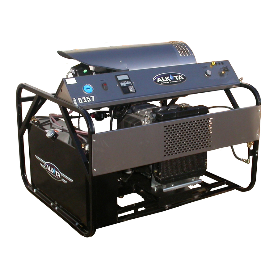
ALKOTA MODEL 5357
SPECIFICATIONS
PERFORMANCE
COMBUSTION SMOKE/BACHARACH SCALE......#1 OR #2 SMOKE
CARBON MONOXIDE ALLOWED.............................................0.01%
HEAT INPUT...........................548,800 BTU/HR / 138,298 KgCAL/HR
DRAFT/STACK INSTALLATION.................0.2" - 0.04" WC READING
GENERAL
WEIGHT (DRY)........................................................960 LBS / 435 KG
FUEL TANK CAPACITY................................................2.7 GAL / 10 L
FUEL TANK CAPACITY................................................9.5 GAL / 36 L
HOSE - PUMP TO UNLOADER...............................P/N K02-03222A2
HOSE - UNLOADER TO COIL.................................P/N K02-03248A2
HOSE - GAUGE FROM UNLOADER.......................P/N K02-02224A2
GAUGE, PRESSURE - 5000 PSI.................................P/N Y01-00015
DIMENSIONS........................................................L-54", H-46", W-45"
THERMOSTAT, PROBE...............................................P/N F04-00856
TRIGGER GUN......................................................... P/N J06-00158-B
PUMP
BUSHING, PULLEY ....................................................P/N R04-00001
PULLEY .......................................................................P/N R03-75100
UNLOADER
VALVE, SAFETY ........................................................P/N C03-00518
PUMP ENGINE
AIR CLEANER..........................................................P/N F05-00485-03
PRE-CLEANER OIL FILTER ...................................P/N F05-00485-02
BUSHING, PULLEY .....................................................P/N R04-00002
PULLEY .......................................................................P/N R03-00747
ELECTRICAL
GENERATOR 115V......................................................P/N F05-00112
PULLEY ......................................................................P/N 4205-00162
SCREW, SET - GENERATOR PULLEY......................P/N HO4-31305
BURNER
MOTOR - .1/5 HP........................................................ P/N V00-20554
VOLTAGE...................................................................115V 1PH 60HZ
FUEL PUMP ......................................(DAN FOSS) P/N V-100714-001
TYPE.............................................................PRESSURE ATOMIZING
FUEL TYPE............................................................. #1 OR #2 DIESEL
03-29-05 Z08-04034
Advertisement
Table of Contents

Related Manuals for ALKOTA 5357

Summary of Contents for ALKOTA 5357
- Page 1 ALKOTA MODEL 5357 SPECIFICATIONS PERFORMANCE DISCHARGE VOLUME...........5.0 GPM / 18.9 LPM COMBUSTION SMOKE/BACHARACH SCALE..#1 OR #2 SMOKE PUMP HEAD PRESSURE........3500 PSI / 241 BAR CARBON MONOXIDE ALLOWED..........0.01% TEMPERATURE RISE....130°F @ 5.0 GPM / 54°C @ 18.9 LPM HEAT INPUT......548,800 BTU/HR / 138,298 KgCAL/HR TEMPERATURE LIMIT........UP TO 200 DEGREES...
-
Page 2: Maintenance Record
MACHINE RECORD MAINTENANCE RECORD SERIAL NUMBER DATE OF PURCHASE PLACE OF PURCHASE NOTES: 01-08-04 Z08-04527 ECN-03022... - Page 3 5357 - OPERATION TABLE OF CONTENTS OIL FIRED ENGINE DRIVEN CLEANER TROUBLESHOOTING SAFETY INSTRUCTIONS Page Number Page Number Safety Symbols • Machine 12, 13 • General • Water Heater • Mechanical • Oil Burner See Parts List Section • Electrical •...
-
Page 4: Machine Unpacking
SAFETY, INSTALLATION, AND OPERATION ENGINE DRIVEN OIL FIRED CLEANER MACHINE UNPACKING GENERAL SAFETY ALL CLEANERS ARE CAREFULLY INSPECTED 1. Before operating this machine, read and observe AND CARTONED TO PROTECT AGAINST SHIPPING all safety, unpacking, and operating DAMAGE. IF THERE IS DAMAGE OR MISSING instructions. -
Page 5: Mechanical Safety
15. Do not start the machine unless the gun 5. DO NOT start the engine until you have assembly is firmly gripped by the machine observed all safety and operating instructions operator. Failure to do this could result in injury found in the engine manual.. -
Page 6: Installation
INSTALLATION 10. CHEMICALS: Mix chemicals per the chemical manufacturers printed directions. Follow all mixing, handling, application, and disposal This machine emits CARBON MONOXIDE, a instructions. Wear gloves, boots, goggles, and DEADLY GAS, and must be vented if used in an protective clothing appropriate for the chemical enclosed area. -
Page 7: Pre-Start-Up
♦ METERING VALVE (if so equipped): Make sure OPERATING the metering valve closed before INSTRUCTIONS operation. If air enters the system through this valve, poor performance and machine damage will occur. Refer to the metering valve insert PRE START-UP for proper operation. 1. - Page 8 and/or oil are present, hot water and WARNING: RISK OF INJECTION OR SEVERE chemical will accelerate in the cleaning INJURY. KEEP CLEAR OF NOZZLE. DO process. NOT DIRECT DISCHARGE STREAM AT 6. TO APPLY CHEMICAL: PERSONS. THIS EQUIPMENT IS TO BE USED ONLY TRAINED...
- Page 9 COMBINATION OPTION 6. To CLEAN: INSTRUCTION A. Start on the lower portion of the area to be cleaned and work up using long, even, overlapping strokes. WARNING: This machine should be B. Regulate the temperature indicated on the operated only by personnel instructed in and thermometer to 300°F by turning the regulating familiar with its operation.
-
Page 10: Machine Maintenance
MACHINE MAINTENANCE GAS ENGINE DRIVEN OIL FIRED CLEANERS FLUSHING 5. Check the position of the ball valve (if so equipped) on the outlet of the float tank assuring it is in the closed position. 1. Connect machine to a pressurized water 6. - Page 11 MACHINE MAINTENANCE CONT’D GAS ENGINE DRIVEN OIL FIRED CLEANERS BELT TENSION COIL BACK PRESSURE CHECK INSTRUCTIONS DEFLECTION DISCHARGE VOLUME BACK PRESSURE REQUIRING DESCALING 2-3 GPM 50 PSI 3-4 GPM 75 PSI 4-5 GPM 100 PSI 6 GPM 150 PSI SPAN 1.
- Page 12 MACHINE MAINTENANCE EACH AFTER EVERY EVERY EVERY ENGINE DRIVEN OIL FIRED FIRST DAIL Y YEARLY CLEANERS FIRST 8 HRS OIL BATH W A TER PUM P : Oil Level – check and add as needed per PUMP SERVICE insert. O i l Change – drain and refill per PUM P CAUTION: SERVICE insert...
- Page 13 CLEANER TROUBLESHOOTING GAS ENGINE DRIVEN HOT WATER CLEANERS TROUBLE POSSIBLE CAUSE REMEDY Poor A. Hard water. A. Connect machine to water softener. Cleaning B. Low Pressure. B. See “Low operating pressure” Action. C. Little or no chemical being C. See “Machine will not draw chemical”. drawn.
- Page 14 CLEANER TROUBLESHOOTING (CONT.) ELECTRIC DRIVEN HOT WATER CLEANERS TROUBLE POSSIBLE CAUSE REMEDY A. See PUMP TROUBLESHOOTING. 4. Excessive, A. Pump unusual B. Defective engine. B. Call service technician or take engine to noise. Repair/Warranty station. C. Pulleys rubbing. C. Adjust shields or pulley(s). D.
- Page 15 OIL FIRED WATER HEATER TROUBLESHOOTING TROUBLE POSSIBLE CAUSE REMEDY A. See BURNER on MODEL 1. Machine will not rise to A. Low fuel pressure. SPECIFICATIONS for specified pressure. operating temperature B. Water in fuel piping. B. Drain fuel tank and remove and replace filter per FUEL FILTER INSERT.
- Page 16 ASSEMBLY, FLOAT TANK EXPLODED VIEW - P/N 5405-01121 WATER INLET FROM UNLOADER VALVE TO PUMP PART LISTS ITEM PART NUMBER PART DESCRIPTION QTY. 5305A-04120 WELDMENT, TANK - FLOAT 5405-10548P ASSEMBLY, RESTRICTOR AR14-00100-B ROD, FLOAT C03-00622-B BALL,FLOAT-PLASTIC C03-00629-01 NUT, HEX C03-00629-02 WASHER, FIBER C03-00636 VALVE, FLOAT...
- Page 17 V V V V V AL ALVE, VE, FL FLO O O O O A A A A A T T T T T P/N C03-00636 SPECIFICA SPECIFICA SPECIFICA SPECIFICA SPECIFICATIONS TIONS TIONS TIONS TIONS • MAXIMUM FLOW 14 GPM / 53 LPM / 35 PSI •...
- Page 18 ASSEMBLY, CHASSIS - SPLIT EXPLODED VIEW - P/N 8305-05105 PART LISTS ITEM PART NUMBER PART DESCRIPTION QTY. 4120-00116 WELDMENT, HEAD - BURNER 4205A-00111 WELDMENT, COIL - 18" 550-00117 WELDMENT, HEAD - EXHAUST AS1693008PBR WRAPPER, CHASSIS - LOWER AS1693011PBR WRAPPER,COIL 20 1/2 x 27 E06-00002-3 COUPLING, HALF E15-00055-9...
-
Page 19: Oil Level
GENERAL PUMP MAINTENANCE OIL LEVEL 6. Malfunctioning valve assemblies must be replaced. 7. Lubricate a new o-ring with the pump crankcase oil and install into valve cavity in the head. Install a good valve assembly into the cavity as illus- trated. - Page 20 ASSEMBLY, PUMP EXPLODED VIEW - P/N 5357-00501 PART LISTS ITEM PART NUMBER PART DESCRIPTION QTY. 4355EB-00513 MOUNT, PUMP C03-00810 VALVE, AIR C09-00008 VALVE, EASY START E04-00002-58 BUSHING, PIPE E04-00016-58 BUSHING, PIPE E06-00085-48 FITTING, ADAPTER E07-00006-5 CROSS, PIPE - HIGH PRESSURE...
-
Page 21: Plunger Installation
GENERAL PUMP MAINTENANCE PLUNGER SERVICE 4. Remove the plunger from the cross head and 1. Remove pump head per “HEAD REMOVAL”. examine it for cracks, scoring, or pitting. 2. Remove any packings and retainers left on the 5. Remove and discard copper flinger washer, clean plungers by pulling them straight off. -
Page 22: Head Installation
GENERAL PUMP MAINTENANCE HEAD INSTALLATION checking for binding or damage. Discard and 1. Prepare pump head per instructions in replace damaged items. “PACKING SERVICE”. 6. Lubricate packing cavities in the head and all 2. Rotate the plungers so the outer plungers are packings and adapters with pump crankcase oil. -
Page 24: Pump Troubleshooting
PUMP TROUBLESHOOTING TROUBLE POSSIBLE CAUSE REMEDY 1. Oil leaking in the A. Worn crankshaft seal. A. Remove and replace. area of water pump B. Bad bearing. B. Remove and replace. crankshaft. C. Grooved shaft. C. Remove and replace. D. Failure of retainer o-ring D. - Page 25 PUMP TROUBLESHOOTING TROUBLE POSSIBLE CAUSE REMEDY 9. Dirty or worn check A. Normal wear. A. Remove and replace. valves. B. Debris B. Check for lack of water inlet screens. 10. Presence of metal A. Failure of internal component. A. Remove and disassemble to find particles during oil probable cause.
- Page 26 M10 X 1.5...
- Page 28 ASSEMBLY, UNLOADER EXPLODED VIEW - P/N 5357-00515 PART LISTS ITEM PART NUMBER PART DESCRIPTION QTY. Y01-00123 ACCUMULATOR 4355EB-00514 BRACKET, UNLOADER - VALVE W02-10040-8 BARB, HOSE E07-00006-5 CROSS, PIPE - HIGH PRESSURE E08-00010-5 ELBOW, PIPE E08-00011-58 ELBOW, PIPE E14-00010-68 NIPPLE, PIPE - HEX...
-
Page 33: Transformer Test
OIL BURNER MAINTENANCE OIL FIRED CLEANERS DANFOSS PUMP AIR BAND ADJUSTMENT Shut off fuel supply. NOTE: The air band adjustment on this burner Loosen the 2 screws with 7/64 allen wrench has been preset at the factory (elevation one turn. approximately 1400 feet). - Page 34 OIL BURNER MAINTENANCE OIL FIRED CLEANERS BUSS BAR ALIGNMENT 7. Partially close transformer. Check if buss bars align and contact the transformer electrodes. 1. With burner off, loosen screw and swing the If buss bars do not contact, see Buss Bar transformer away from burner gun assembly.
- Page 35 OIL FIRED BURNER TROUBLESHOOTING TROUBLE POSSIBLE CAUSE REMEDY 1. Burner will not A. Electrodes out of alignment. A. See "ADJUSTING ELECTRODE ASSEMBLY" in BURNER ignite. M A INTENANCE SECTION. B. Electrode insulator failure. B. Remove and replace if there are breaks, cracks, or spark trails.
-
Page 36: Oil Burner Troubleshooting
OIL BURNER TROUBLESHOOTING TROUBLE POSSIBLE CAUSE REMEDY 4. Pulsating pressure A. Partially clogged fuel pump A. Remove and replace strainer per FUEL PUMP FILTER in OIL BURNER strainer or filter. MAINTNANCE Section. B. Air leaking around fuel pump B. Check fuel pump cover screws for cover. - Page 39 ASSEMBLY, CONTROL PANEL EXPLODED VIEW - P/N 5357-00306 METERING VALVE TEMP. CONTROL PRESSURE GAUGE LOMBARDINI CONTROL, INCLUDED WITH ENGINE ROCKER SWITCH BURNER HOUR METER FROM BURNER J-BOX FROM BURNER J-BOX 01-12-05 Z08-04750...
- Page 40 PART NUMBER ES-00559...
Need help?
Do you have a question about the 5357 and is the answer not in the manual?
Questions and answers