
Subscribe to Our Youtube Channel
Related Manuals for CSH PUTNAM

Summary of Contents for CSH PUTNAM
- Page 1 INSTRUCTION MANUAL for Installing NO.1 PUTNAM ROLLING LADDERS AND HARDWARE PL.210, PL.230 (Top Guide Assemblies) PL.270-S, PL.270-C (Bottom Wheel Assemblies)
-
Page 2: Pre-Installation
1-3/4” 2-1/8” dia 2-1/8” dia 6-1/2” 6-1/2” 5-1/2” 5-1/2” Pre installation 6-1/2” 6-1/2” 4” CC 4” CC 4” CC 4” CC Instruction Manual for No.1 Putnam Rolling 5-1/2” 5-1/2” 8-1/4” 8-1/4” 8” 8” 8” 8” M5x18 8-1/4” 8-1/4” M5x18 (x1) - Page 3 Figure 2 2. Splice the sections of rails together using the supplied wooden dowels. Do not put Rail Wooden dowel rail brackets in the area where the splices will be located (see figure 2) . 3. Install rail brackets a. For vertical brackets (PL.14 series): Drive the brackets into the slotted rail and align them with the vertical uprights/stiles on the shelving unit.
- Page 4 For the Corner Brace/Bracket (PL.40CRVBKT series) used in conjunction with the 90º, 30” radius curved rails (see diagrams below) • Install the Corner Brace/Bracket by measuring from the inside corner of the 90-degree trim boards out 23 1/4” for both sides. •...
- Page 5 Incorrect Correct 3. Using the supplied #14 x 21/2” round-head screws, secure the step to the side rail through the predrilled holes on the side rails. Assemble the remaining steps in the same manner (see figure 3a) . 4. Once all the steps are assembled onto one of the side rails, position the side rail on its side with the steps pointing up and insert the top turned rung (see figure 3b) .
- Page 6 Step 3: Attaching the Hardware to the Ladder 1. Install the upper roller and hook assemblies (Straight Side Rails). a. Center the upper assembly around the top turned dowel. Measure down from the top of the ladder to the top of the Upper Assembly hardware (approx. 11/2”). This measurement should be the same on both wood side rails (see figure 5) .
- Page 7 2. Using a 1/4” drill bit, drill out the through holes for the 1/4-20 Phillips, pan-head 1 3/8” long bolts. We recommend this procedure: • Using the holes in the upper assembly as a drill guide, drill a ¼” hole halfway through the thickness of the ladder slide rail.
- Page 8 Pre-drill the ladder side rail for the #10 Flat-head, Phillips drive ¾” screw (see figure 9) . PLEASE NOTE: Pre-drilling is essential to prevent splitting the wood. e. Install the bottom wheel assemblies using the included screws, bolts, and acorn nuts. Figure 9c Figure 9a Figure 9b ...and your Putnam Ladder is complete!
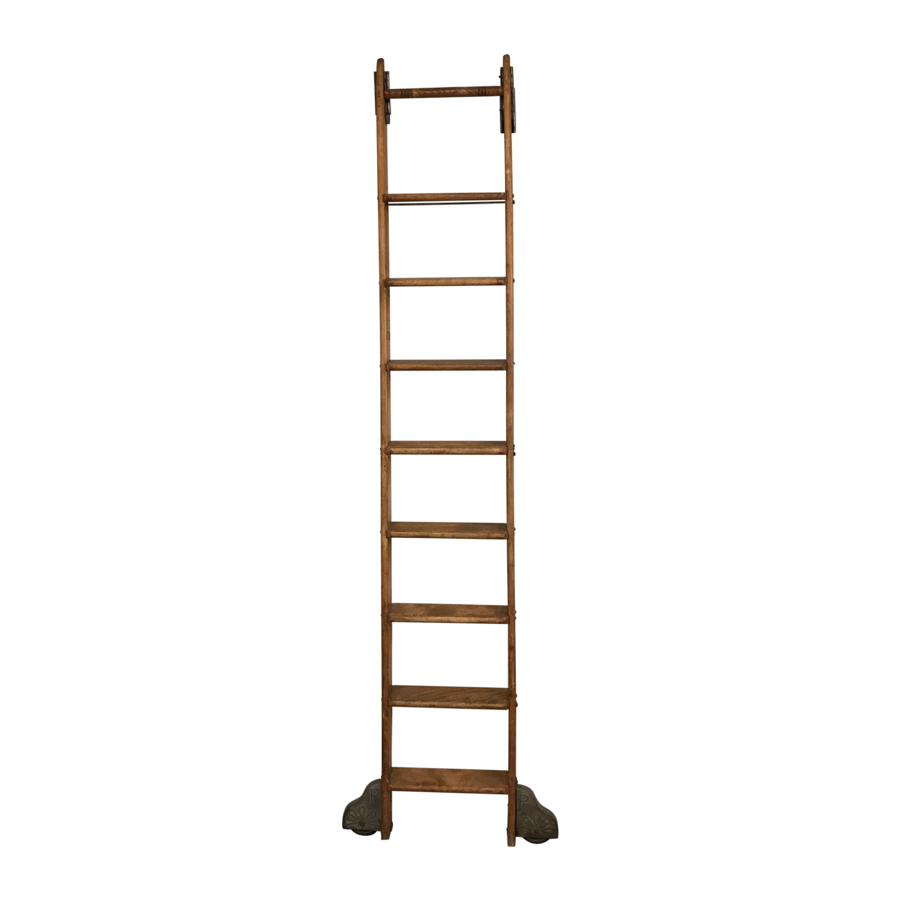
- Page 9 Putnam Ladder Application Images...
-
Page 10: Hardware Dimensions
Hardware Dimensions ” ” ⁄ ⁄ ⁄ ” ” ⁄ ” ” ” ⁄ ⁄ ” ⁄ ⁄ Bottom Wheel Measurements Bottom Wheel Measurements ” • Length - 6 ⁄ ” • Length - 6 ⁄ ” ” • Width - 2 ⁄... - Page 11 Hardware Dimensions ” ” ” ” ⁄ ⁄ ⁄ ⁄ ” ⁄ 5” Vertical Hook Bracket Measurements Vertical Bracket Measurements ” ” • Length - 1 ⁄ • Length - 1 ⁄ ” ” • Width - 1 ⁄ • Width - 1 ⁄...
- Page 12 Also available from CSH: Mini Barn Door Hardware Rolling Barn Door Hardware InvisiDoor 1170 Wauwatosa Rd. Cedarburg, WI 53012 (262) 365-7960 cshardware.com REV. 5.26.21...
Need help?
Do you have a question about the PUTNAM and is the answer not in the manual?
Questions and answers