Advertisement
Quick Links
Installation Instructions
GPSD-6-60 & SHK[G]-6-60 Series
SW3-031 - v1.2
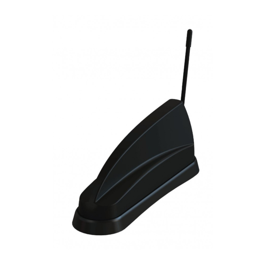
1. Introduction
The GPSD/SHK[G]-6-60 series is a multi-function antenna with 2x2 MiMo for 4G/5G LTE. The GPSD & SHKG versions incorporate an active GPS/GNSS
antenna with 26dB gain LNA. The GPSD version has a M6 stud (under a blanking cover) for an optional comms whip. Additionaly, versions of each type are
available with 2x2, 3x3 or 4x4 MiMo dual band WiFi antennas. This antenna is suitable for fitment to vehicle panels of up to 8mm (0.31"), although an optional
thick panel fitting kit is available. Heat shrink tubes are included in the kit, to enable the coaxial connections to be sealed as an extra precaution if required.
2. Mounting requirements and selecting location
For optimum performance, it is recommended that the antenna is fitted on a conductive (metal) panel. For SHK(G) and GPSD (with no whip fitted), it is
possible to mount the antenna on a non-conductive panel with acceptable performance for all the antenna functions. For GPSD type, with comms whip fitted,
the antenna must be fitted on a conductive ground plane - recommended size is ½ wave length diameter at the lowest frequency of whip operation. To
calculate this size, use formula below:
150 / frequency in MHz = ½ wavelength (m)
Example: 150MHz =100cm (39.4"); 400MHz = 38cm (15"); 900MHz =16cms (6.3").
When fitting the GPSD with comms whip on a non-metallic panel, a ground plane plate of suitable size should be fabricated and fitted under the mounting
panel. In all cases the earthing washer must make low resistance electrical contact with the ground plane plate (<0.2Ω). Select a mounting location, checking
for any roof curvature to ensure that the antenna base contacts evenly on the mounting surface. The antenna should be located as far as possible from
surrounding roof mounted items (e.g light bar, air con unit). Ensure that there is adequate under panel clearance and that there is no double skin panel or
cross brace present. Measure to check for central position if applicable.
2. Prepare and drill hole
Mask panel area around hole position to protect paintwork and headliner. Drill a pilot hole, and then increase to 19mm (3/4"),
ensuring that drill/cutter bit does not contact headliner. Clean area around the hole, carefully removing all burrs and swarf.
Hole
Remove paint and primer from under panel surface to ensure effective earth contact by washer and nut. Apply some
∅19
petroleum jelly or paint around the hole to prevent corrosion.
Fig.1
3. Fitting the antenna
Remove protective backing from underside of antenna, feed coaxial cables through panel. Position the antenna over the hole ensuring correct orientation
and stick to panel by applying firm downward pressure.
When fitting the nut, it is important to ensure that the cables are held centrally whilst the nut is correctly started on the threads. The nut should fit freely by
hand and only require a final tighten by spanner to a recommended torque of 5Nm. It is important not to over-tighten the nut as this can cause damage to the
mounting panel. For GPSD, if using comms whip, remove blanking cap and screw whip securely to mounting stud.
Advertisement

Related Manuals for Panorama Antennas GPSD-6-60 Series


Summary of Contents for Panorama Antennas GPSD-6-60 Series
- Page 1 Installation Instructions GPSD-6-60 & SHK[G]-6-60 Series SW3-031 - v1.2 1. Introduction The GPSD/SHK[G]-6-60 series is a multi-function antenna with 2x2 MiMo for 4G/5G LTE. The GPSD & SHKG versions incorporate an active GPS/GNSS antenna with 26dB gain LNA. The GPSD version has a M6 stud (under a blanking cover) for an optional comms whip. Additionaly, versions of each type are available with 2x2, 3x3 or 4x4 MiMo dual band WiFi antennas.
- Page 2 4. Routing and terminating coaxial cable(s) If heat shrink tubes are to be used, slide onto antenna cable tails prior to connecting extension cables – it is recommended that these are heat shrunk only after all tests have been satisfactorily completed. Connect extension coaxial cables to antenna, ensuring that the connectors are fully inserted and tightened, then route to equipment.